Nissan Rogue (T33) 2021-Present Service Manual: Admission Valve
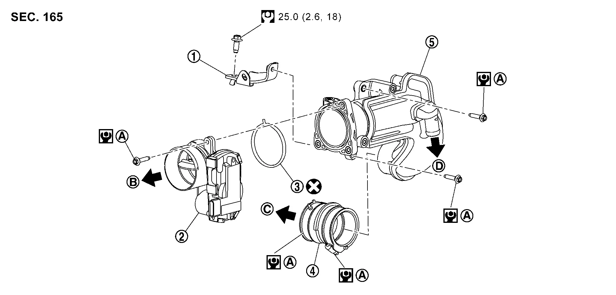
Exploded View
 |
Air duct bracket |  |
Admission valve |  |
gasket |
 |
Air duct hose |  |
Air duct | ||
 |
Comply with the installation procedure when tightening. Refer to Removal and Installation. |  |
To air duct. Refer to Exploded View. |  |
To turbocharger. Refer to Exploded View. |
 |
To EGR volume control valve. Refer to Removal and Installation . | ||||
 |
: Always replace after every disassembly. | ||||
 |
: N·m (kg-m, ft-lb) | ||||
 |
: N·m (kg-m, in-lb) | ||||
Removal and Installation
REMOVAL
Admission Valve
Remove engine cover. Refer to Removal and Installation.
Remove resonator. Refer to Removal and Installation.
Remove air duct. Refer to Removal and Installation.
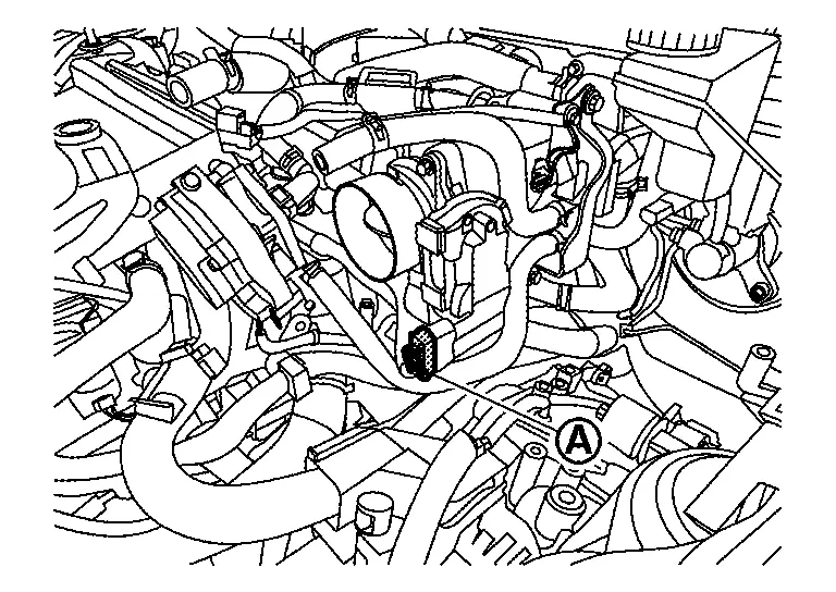
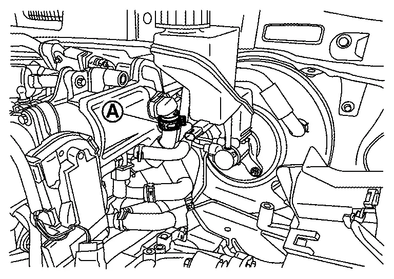
Disconnect admission valve harness connector .
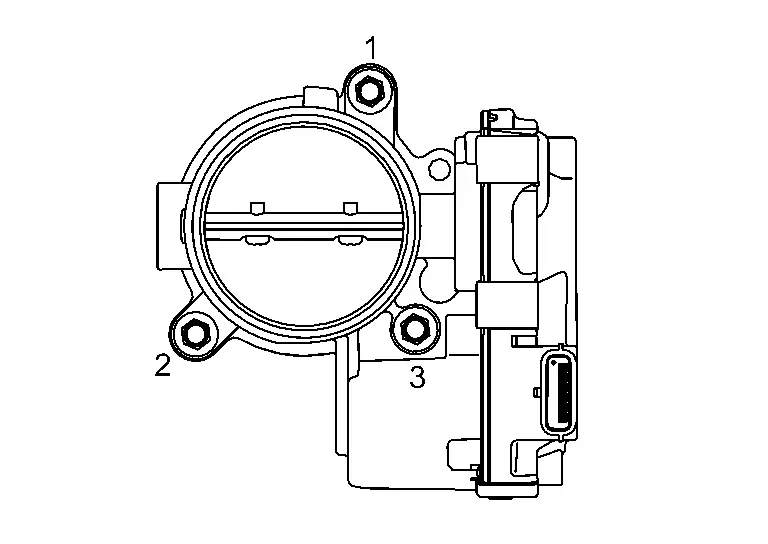
Loosen the admission valve nuts in the reverse order as shown.
Remove the admission valve and gasket.
Air Duct and Air Duct Hose
Remove cowl top extension. Refer to Removal and Installation.
Remove admission valve.
Remove purge control valve. Refer to Removal and Installation.
Remove purge control valve bracket 1 and purge control bracket 2. Refer to Removal and Installation.
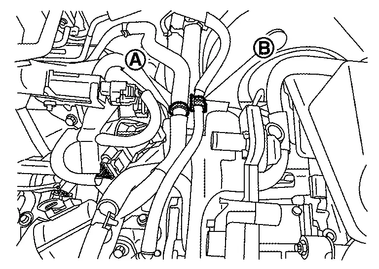
Remove turbo hose from air duct side . Refer to Removal and Installation.
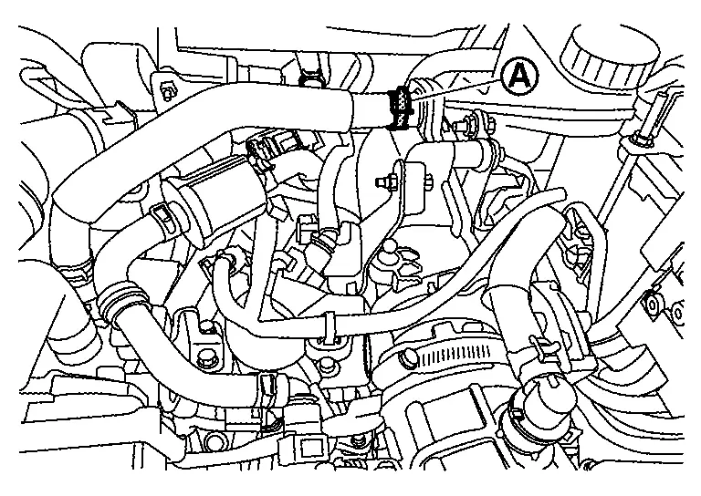
Remove back pressure hose air duct side . Refer to Removal and Installation.
Disconnect Resonator hose 2 and fuel hose from air duct.
Loosen air duct hose clamp on the turbocharger side.
Remove air duct mounting bolts. Refer to Removal and Installation..
Remove air duct hose together with air duct. Refer to Removal and Installation.
Loosen air duct hose clamp and remove air duct hose from air duct.
Remove air duct bracket if necessary.
CAUTION:
Do not reuse the O-ring.
INSTALLATION
CAUTION:
Do not reuse the O-ring.
Install air duct bracket if removed.
Install air duct hose and air duct to turbocharger.
Tighten the bolts and clamp of air duct in numerical order as shown.
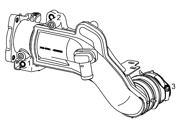
| Air duct hose clamp |
: 5.1 N·m (0.52 kg-m, 45 in-lb) |
| Air duct bolts |
: 10.0 N·m (1.0 kg-m, 89 in-lb) |
Tighten the nuts of admission valve in numerical order as shown.
|
: 10.0 N·m (1.0 kg-m, 89 in-lb) |
Install in the reverse order of removal after this step.
Other materials:
Dtc/circuit Diagnosis. B2426-12 Spindle Sensor Lh
DTC Description
DTC DETECTION LOGIC DTC No.
CONSULT screen items
(Trouble diagnosis content) DTC Detection Condition
B2426-12
Spindle sensor LH
(Spindle sensor left hand)
Diagnosis condition
When the door unlock operates while ignition switch is OFF (auto ACC OFF status) or the ba ...
Its Can Communication 4 Circuit
Diagnosis Procedure
CHECK NETWORK DIAGNOSIS
Check the "Network diagnosis" results from CONSULT to see that the diagnostic CAN communication circuit have no malfunction.
Are the diagnostic CAN communication circuit normal?
YES>>
GO TO 2.
NO>>
Check and repair diagnostic CAN commu ...
U0644 Sent Communication
DTC Description
DTC DETECTION LOGIC DTC No.
CONSULT screen terms
(Trouble diagnosis content) DTC detecting condition
U0644
00
Lost comm with w/g posi sen (b1)
(Lost Communication With Wastegate Position Sensor "A")
Diagnosis condition
Battery voltage: 8 V or more
Igni ...