
Nissan Rogue (T33) 2021-Present Service Manual: Plug
Description
Replace the O-ring if oil leaks from the plug.
Exploded View
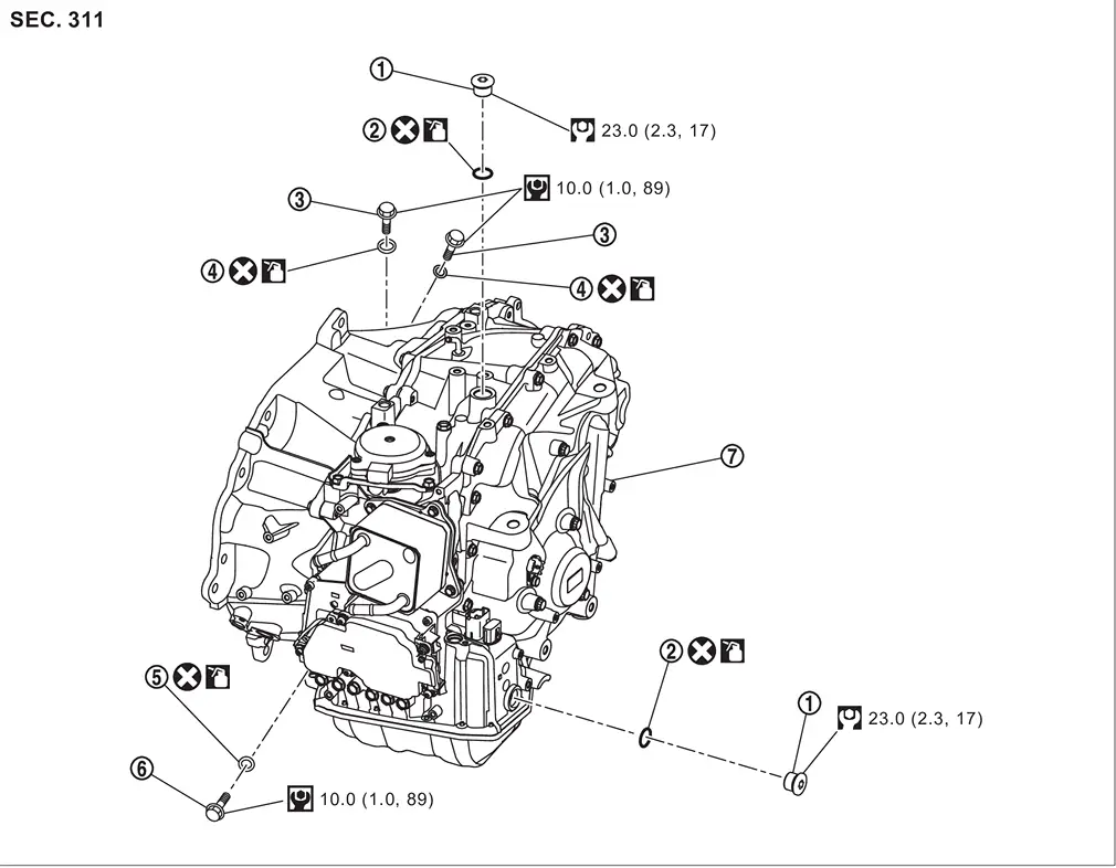
| 1. | Plug | 2. | O-ring | 3. | Plug |
| 4. | O-ring | 5. | O-ring | 6. | Overflow plug |
| 7. | O-ring | 8. | Transaxle assembly |
 : N·m (kg-m, ft-lb)
 : N·m (kg-m, in-lb)
 : Always replace after every disassembly.
 : Apply CVT fluid.
Removal and Installation
REMOVAL
| Never Reuse These Parts | Part Code | For additional information: |
|---|---|---|
| Seal-O-ring | 31526QB | Exploded View |
| Seal-O-ring | 31526Q | Exploded View |
| Seal-O-ring | 31526QA | Exploded View |
 NOTE:
Replace the O-rings if oil leaks from the plug.
Remove the plug from the top of the Transaxle assembly
Remove air duct and air cleaner. Refer to Removal and Installation.
Remove 12V battery. Refer to "Removal and Installation.
Remove battery tray. Refer to Removal and Installation.
Remove plug and O-ring.
Remove the plug from the side of the Transaxle assembly
Remove engine under cover. Refer to Removal and Installation.
Remove splash guard and front fender protector. Refer to Removal and Installation
Remove plug and O-ring.
INSTALLATION
Installation is in the reverse order of removal.
CAUTION:
-
Never reuse O-ring.
-
Apply CVT fluid to O-ring.
Inspection and Adjustment
Check for CVT fluid leakage. Refer to Inspection.
Adjust CVT fluid level. Refer to Adjustment.
Other materials:
Operation
Switch Name and Function
OPERATION AND DISPLAY OF AUTOMATIC AIR CONDITIONING SYSTEMDisplay: Display in A/C switch assembly
Air conditioning operation status is indicated on display in A/C switch assembly.
Air conditioning status display screen is indicated when MODE switch is pressed while ...
Symptom Diagnosis. Door Does Not Lock/unlock and Engine Does Not Start (all I-Key/req Sw/push Sw)
Description
All doors do not lock/unlock using door request switch and engine
does not start when push-button ignition switch is pressed while
carrying Intelligent Key.SYMPTOM TABLE (BOTH INTELLIGENT KEYS HAVE THE SAME SYMPTOMS) Door lock operation (remote keyless entry)
Door lock operation ...
Accessory Relay
Diagnosis Procedure
CHECK ACCESSORY RELAY POWER SUPPLY
Disconnect accessory relay connector.
Check voltage between accessory relay harness connector and ground.
(+) (–)
Voltage
(Approx.)
Accessory relay
Connector Terminal
J-5
2
Ground
Battery voltage
3
...