Nissan Rogue (T33) 2021-Present Service Manual: Accessory Relay
Diagnosis Procedure
CHECK ACCESSORY RELAY POWER SUPPLY
-
Disconnect accessory relay connector.
-
Check voltage between accessory relay harness connector and ground.
(+) (–) Voltage
(Approx.)Accessory relay Connector Terminal J-5 2 Ground Battery voltage 3
Is the inspection result normal?
YES>>GO TO 2.
NO>>Repair or replace harness or connectors.
CHECK ACCESSORY RELAY
Check accessory relay. Refer to Component Inspection.
Is the inspection result normal?
YES>>GO TO 3.
NO>>Replace accessory relay.
CHECK ACCESSORY RELAY CONTROL SIGNAL CIRCUIT
-
Disconnect BCM connector.
-
Check continuity between BCM harness connector and accessory relay harness connector.
With type A meter BCM Accessory relay Continuity Connector Terminal Connector Terminal M51 30 J-5 1 Yes With type B meter BCM Accessory relay Continuity Connector Terminal Connector Terminal M18 34 J-5 1 Yes -
Check continuity between BCM harness connector and ground.
With type A meter BCM — Continuity Connector Terminal M51 30 Ground No With type B meter BCM — Continuity Connector Terminal M18 34 Ground No
Is the inspection result normal?
YES>>Replace BCM. Refer to Removal and Installation.
NO>>Repair or replace harness or connectors.
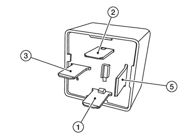
Component Inspection
CHECK ACCESSORY RELAY
-
Ignition switch OFF.
-
Disconnect accessory relay connector.
-
Check continuity between accessory relay terminals.
| Accessory relay | Condition | Continuity | |
|---|---|---|---|
| Terminals | |||
 |
 |
12 V direct current supply between terminals  and and  . . |
Yes |
| No current supply | No | ||
Is the inspection result normal?
YES>>Inspection End.
NO>>Replace accessory relay.
Other materials:
Transfer: Ty92a. Precaution. Precautions
Precautions
PRECAUTIONS FOR SUPPLEMENTAL RESTRAINT SYSTEM (SRS) AIR BAG AND SEAT BELT PRE-TENSIONER
: Precautions
The Supplemental Restraint System such as “AIR BAG” and “SEAT BELT
PRE-TENSIONER”, used along with a front seat belt, helps to reduce the
risk or severit ...
P26a5 Multi-Way Control Valve Position Sensor
DTC Description
DTC DETECTION LOGIC DTC
CONSULT screen terms
(Trouble diagnosis content) DTC detection condition
P26A5
00
ENGINE COOLANT B/V A POSI SEN
(Engine coolant bypass valve A position sensor circuit range/performance)
Diagnosis condition
—
Signal (terminal)
Mu ...
C10b0-09 Parking Brake Actuator (rh)
DTC Description
DTC DETECTION LOGIC DTC No.
CONSULT screen terms
(Trouble diagnosis content) DTC detection condition
C10B0
09
Parking brake actuator (RH)
[Parking brake actuator (right)]
Diagnosis condition
When parking brake is apply
Signal (terminal)
—
Threshol ...