Nissan Rogue (T33) 2021-Present Service Manual: B2fac-14 Accessory Relay
DTC Description
DTC DETECTION LOGIC
| DTC No. |
CONSULT screen items (Trouble diagnosis content) | DTC detection condition | |
|---|---|---|---|
| B2FAC-14 |
Accessory relay (Accessory relay) |
Diagnosis condition | When ignition switch is OFF (not auto ACC status) |
| Signal (terminal) | Accessory relay control signal [terminal #30 (with type A meter) or #34 (with type B meter)] | ||
| Threshold | 0 V | ||
| Diagnosis delay time | 1 second or more | ||
POSSIBLE CAUSE
-
Harness or connectors (accessory relay control signal circuit is open or shorted to ground)
-
Accessory relay
-
BCM
FAIL-SAFE
—
DTC CONFIRMATION PROCEDURE
PERFORM DTC CONFIRMATION PROCEDURE
 CONSULT
-
Ignition switch ON.
-
Ignition switch OFF and wait for 1 minute with the front door LH opened.
-
Ignition switch ON.
-
Select “Self diagnosis result” mode of “BCM”.
Is DTC detected?
YES>>Refer to DTC Diagnosis Procedure.
NO-1>>To check malfunction symptom before repair: Refer to Intermittent Incident.
NO-2>>Confirmation after repair: Inspection End.
DTC Diagnosis Procedure
CHECK ACCESSORY RELAY CONTROL SIGNAL VOLTAGE
-
Ignition switch OFF.
-
Disconnect BCM connector.
-
Check voltage between BCM harness connector and ground.
With type A meter + - Voltage
(Approx.)BCM Connector Terminal M51 30 Ground Battery voltage With type B meter + - Voltage
(Approx.)BCM Connector Terminal M18 34 Ground Battery voltage
Is the inspection result normal?
YES>>Replace BCM. Refer to Removal and Installation.
NO>>GO TO 2.
CHECK ACCESSORY RELAY CONTROL SIGNAL CIRCUIT (OPEN)
-
Disconnect accessory relay connector.
-
Check continuity between BCM harness connector and accessory relay harness connector.
With type A meter BCM Accessory relay Continuity Connector Terminal Connector Terminal M51 30 J-5 1 Yes With type B meter BCM Accessory relay Continuity Connector Terminal Connector Terminal M18 34 J-5 1 Yes
Is the inspection result normal?
YES>>GO TO 3.
NO>>Repair the harness or connector.
CHECK ACCESSORY RELAY CONTROL SIGNAL CIRCUIT (SHORT TO GROUND)
Check continuity between BCM harness connector and ground.
| BCM | — | Continuity | |
|---|---|---|---|
| Connector | Terminal | ||
| M51 | 30 | Ground | No |
| BCM | — | Continuity | |
|---|---|---|---|
| Connector | Terminal | ||
| M18 | 34 | Ground | No |
Is the inspection result normal?
YES>>GO TO 4.
NO>>Repair the harness or connector.
CHECK ACCESSORY RELAY
Check accessory relay. Refer to Component Inspection.
Is the inspection result normal?
YES>>Inspection End.
NO>>Replace accessory relay.
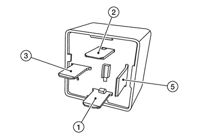
Component Inspection
CHECK ACCESSORY RELAY
-
Ignition switch OFF.
-
Disconnect accessory relay connector.
-
Check continuity between accessory relay terminals.
| Accessory relay | Condition | Continuity | |
|---|---|---|---|
| Terminal | |||
 |
 |
12 V direct current supply between terminals  and and  . . |
Yes |
| No current supply | No | ||
Is the inspection result normal?
YES>>Inspection End.
NO>>Replace accessory relay.
Other materials:
Protection contre la corrosion
Facteurs de corrosion les plus courants
Accumulation de poussière humide, de sable et de débris dans les panneaux de carrosserie, les orifices et les zones peu ventilées.
Dommages de la peinture ou des revêtements protecteurs causés par des projections de gravillons ou de petits accidents ...
Diagnosis System (adas Control Unit 2)
Without Propilot Assist 2.1
Diagnosis Description
APPLICATION ITEMSCONSULT performs the following functions via CAN communication using ADAS control unit 2. Diagnosis mode CGW Status Description
Restricted Mode Diag Test Mode Open Mode
Self Diagnostic Result
Display
Display
Di ...
Jump starting. Push starting
To start your engine using a booster battery, carefully follow the instructions and precautions below.
WARNING
Incorrect jump starting can cause a battery explosion, leading to severe injury or death.
Explosive hydrogen gas is always present around the battery. Keep all sparks, flames, and ...