Nissan Rogue (T33) 2021-Present Service Manual: B2fac-12 Accessory Relay
DTC Description
DTC DETECTION LOGIC
| DTC No. |
CONSULT screen items (Trouble diagnosis content) | DTC detection condition | |
|---|---|---|---|
| B2FAC-12 |
Accessory relay (Accessory relay) |
Diagnosis condition | When ignition switch is ON |
| Signal (terminal) | Accessory relay control signal [terminal #30 (with type A meter) or #34 (with type B meter)] | ||
| Threshold | 16 V or more | ||
| Diagnosis delay time | 1 second or more | ||
POSSIBLE CAUSE
-
Harness or connectors (accessory relay control signal circuit is shorted to battery)
-
Accessory relay
-
BCM
FAIL-SAFE
—
DTC CONFIRMATION PROCEDURE
PERFORM DTC CONFIRMATION PROCEDURE
 CONSULT
-
Ignition switch ON.
-
Select “Self diagnosis result” mode of “BCM”.
Is DTC detected?
YES>>Refer to DTC Diagnosis Procedure.
NO-1>>To check malfunction symptom before repair: Refer to Intermittent Incident.
NO-2>>Confirmation after repair: Inspection End.
DTC Diagnosis Procedure
CHECK ACCESSORY RELAY CONTROL SIGNAL CIRCUIT (SHORT TO BATTERY)
-
Ignition switch OFF.
-
Disconnect BCM connector and accessory relay connector.
-
Check voltage between BCM harness connector and ground.
With type A meter + - Voltage
(Approx.)BCM Connector Terminal M51 30 Ground 0 V With type B meter + - Voltage
(Approx.)BCM Connector Terminal M18 34 Ground 0 V
Is the inspection result normal?
YES>>GO TO 2.
NO>>Repair the harness or connector.
CHECK ACCESSORY RELAY
Check accessory relay. Refer to Component Inspection.
Is the inspection result normal?
YES>>Replace BCM. Refer to Removal and Installation.
NO>>Replace accessory relay.
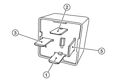
Component Inspection
CHECK ACCESSORY RELAY
-
Ignition switch OFF.
-
Disconnect accessory relay connector.
-
Check continuity between accessory relay terminals.
| Accessory relay | Condition | Continuity | |
|---|---|---|---|
| Terminal | |||
 |
 |
12 V direct current supply between terminals  and and  . . |
Yes |
| No current supply | No | ||
Is the inspection result normal?
YES>>Inspection End.
NO>>Replace accessory relay.
Other materials:
Poste de conduite
Cette vue d’ensemble du poste de conduite du Nissan Rogue vous aide à repérer rapidement les commandes essentielles, que vous conduisiez en ville ou sur autoroute. Selon la finition de votre Nissan Rogue, certaines fonctions peuvent être présentes (signalées par *), notamment ProPILOT Assist ...
Dtc/circuit Diagnosis. C18e4-88 Can Comm Circuit
DTC Description
DTC DETECTION LOGIC DTC No. CONSULT screen terms DTC detection condition
C18E4
88
CAN communication system
1
Diagnosis condition
When Ignition switch is ON.
Signal (terminal)
CAN communication signal
Threshold
When Electrically-driven Intelligent ...
Transfer: Ty92a. Precaution. Precautions
Precautions
PRECAUTIONS FOR SUPPLEMENTAL RESTRAINT SYSTEM (SRS) AIR BAG AND SEAT BELT PRE-TENSIONER
: Precautions
The Supplemental Restraint System such as “AIR BAG” and “SEAT BELT
PRE-TENSIONER”, used along with a front seat belt, helps to reduce the
risk or severit ...