Nissan Rogue (T33) 2021-Present Service Manual: Electric Oil Pump
Exploded View
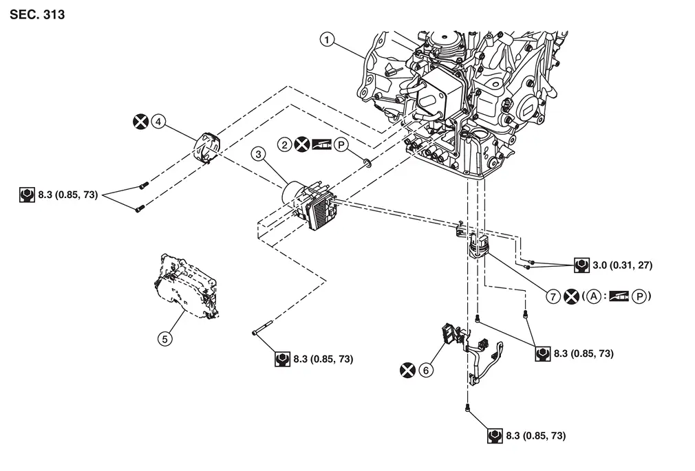
| 1. | Transaxle assembly | 2. | Electric oil pump gasket | 3. | Electric oil pump |
| 4. | Electric oil pump bracket | 5. | TCM | 6. | Terminal assembly B |
| 7. | Terminal assembly A | ||||
| A. | O-ring |
 : N·m (kg-m, in-lb)
 : Always replace after every disassembly.

 : Apply petroleum jelly.
Removal and Installation
REMOVAL
| Never Reuse These Parts | Part Code | For additional information: |
|---|---|---|
| Gasket-oil pump | 31366 | Exploded View |
| Seal-O-ring | 31362M | Exploded View |
| Electric oil pump bracket | 31069B | Exploded View |
Disconnect the negative battery terminal. Refer to Exploded View.
Remove engine under cover. Refer to Exploded View.
Remove drain plug from oil pan and then drain the CVT fluid.
Remove air cleaner and air duct. Refer to Removal and Installation.
Remove the oil pan. Refer to Removal and Installation.
Remove the control valve. Refer to Removal and Installation.
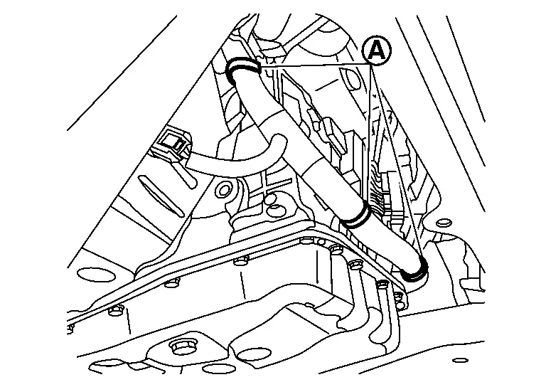
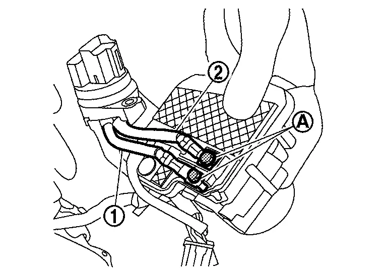
Remove harness clips (A).
Remove TCM. Refer to Removal and Installation.
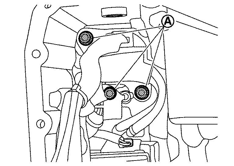
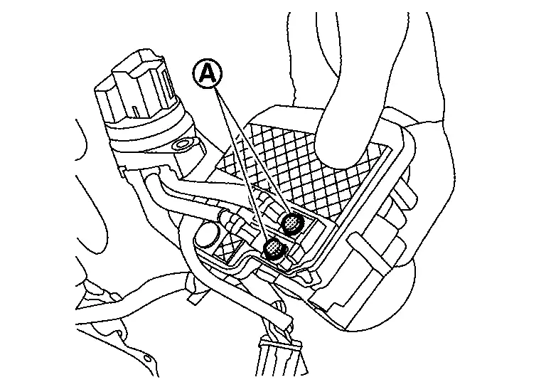
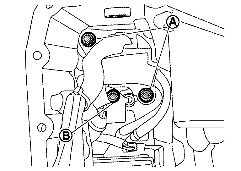
Remove fixing bolts (A) of terminal assembly A and terminal assembly B to the case.
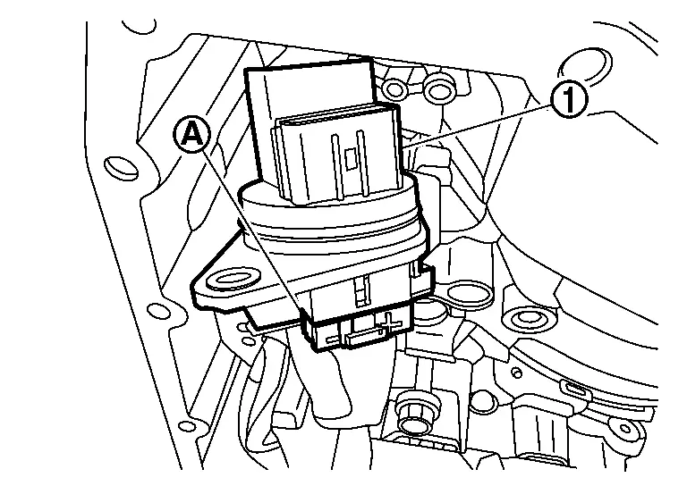
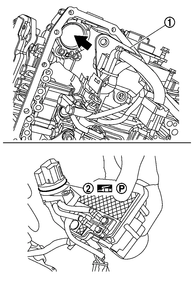
Press terminal assembly A (1) into the transaxle case.
CAUTION:
Before handling terminal assembly A, clean around the exterior of it to revent foreign materials from entering into the transaxle case.
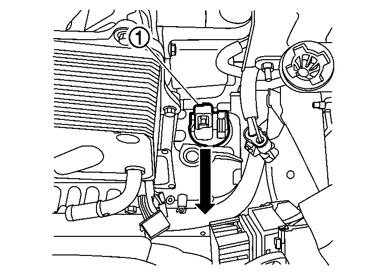
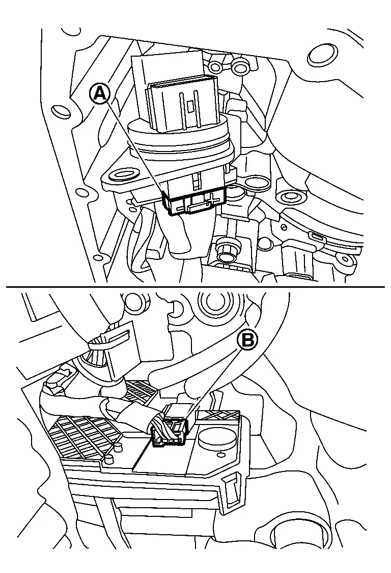
Disconnect harness connector (A) from terminal assembly A (1).
Disconnect harness connector (A) of terminal assembly B (1) from electric oil pump.
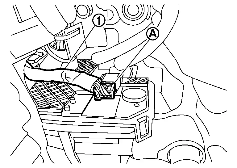
Remove terminal assembly B.
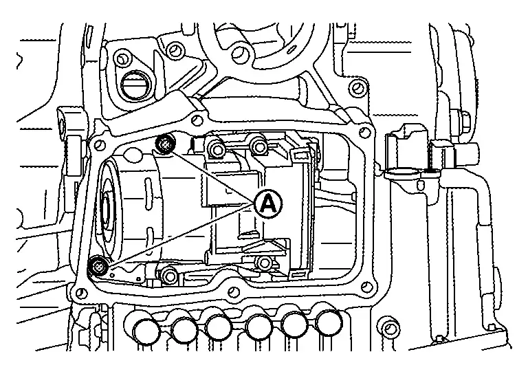
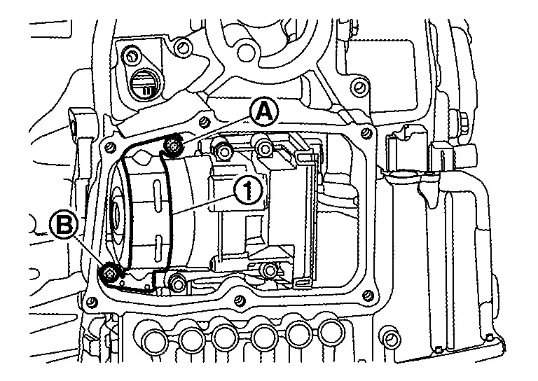
Remove electric oil pump bracket mounting bolts (A).
Remove electric oil pump mounting bolts (A) and then remove electric oil pump (1) and terminal assembly A from transaxle assembly.
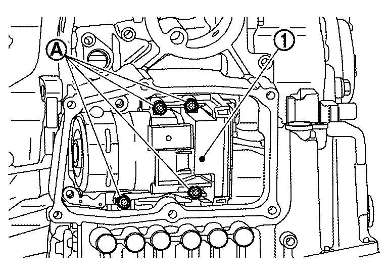
 NOTE:
NOTE:
Take out electric oil pump from the opening for installing TCM.
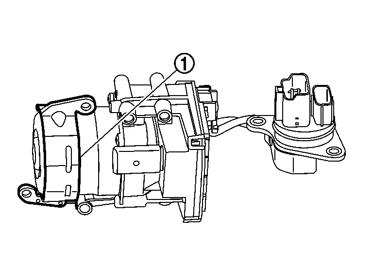
Remove electric oil pump bracket (1) from electric oil pump.
Remove electric oil pump gasket (1).
Remove terminal assembly A mounting bolts (A) and then remove terminal assembly A from electric oil pump.
INSTALLATION
Check that the O-ring (1) is installed on terminal assembly A.
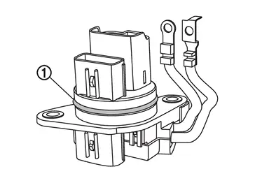
CAUTION:
Never reuse terminal assembly A.
Connect terminal assembly A (1) and (2) to electric oil pump. Tighten mounting bolts (A) of terminal assembly A to the specified torque. Refer to Exploded View.
CAUTION:
Never install terminals in the opposite direction.
Install electric oil pump gasket (1).
NOTE:
When installing, apply petroleum jelly to oil pump gasket.
CAUTION:
-
Never reuse the oil pump gasket.
Install electric oil pump bracket â‘ to electric oil pump.

CAUTION:
Never reuse electric oil pump bracket when replacing electric oil pump with a new one.
Install electric oil pump (1) and terminal assembly A to transaxle. Tighten mounting bolts (A) of electric oil pump to the specified torque. Refer to Exploded View.
Tighten mounting bolts of electric oil pump bracket (1) to the specified torque in numerical order (A) and (B) shown in the figure. Refer to Exploded View.
Install harness connector (A) to terminal assembly A, and then install harness connector (B) of terminal assembly B to the electric oil pump.
CAUTION:
-
Never reuse terminal assembly B.
-
When installing, never include any moisture, contamination into harness connector.
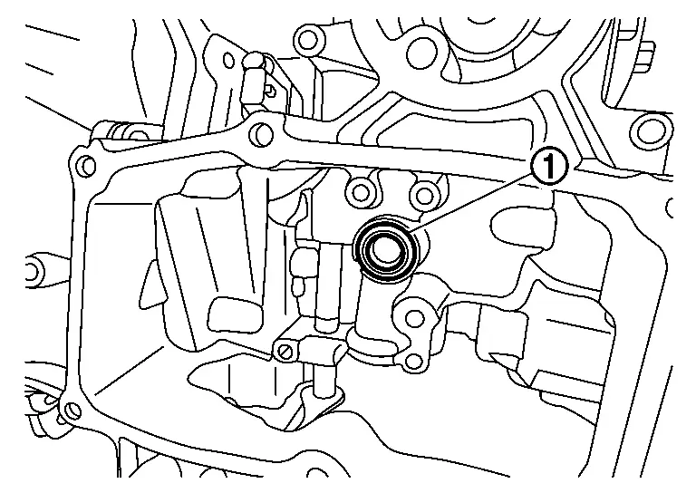
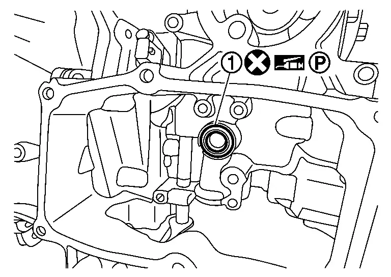
Insert the terminal assembly A (1) to the hole of transaxle case, and then push it to seat completely.
CAUTION:
-
Apply petroleum jelly to O-ring (2) of terminal assembly A.
NOTE:
-
Completely push CVT unit connector until click noise is made.
Tighten each mounting bolt (A) and (B) for terminal assembly A and terminal assembly B with specified torque. Refer to Exploded View.
Install TCM. Refer to Removal and Installation.
Install the control valve. Refer to Removal and Installation.
Install the oil pan. Refer to Removal and Installation.
Install drain plug from oil pan.
Install engine under cover. Refer to Exploded View.
Install air duct and air cleaner. Refer to Exploded View.
Install the negative battery terminal. Refer to Exploded View.
Refill with CVT fluid. Refer to Refilling.
Inspection and Adjustment
Check for CVT fluid leakage. Refer to Inspection.
Other materials:
Dtc/circuit Diagnosis. Power Supply and Ground Circuit
Moonroof Motor Assembly
Diagnosis Procedure
CHECK FUSE
Ignition switch OFF.
Check that the following fuse is not blown (open):
Fuse No. Capacity
31
15 A
Is the fuse blown (open)?
YES>>
Repair the blown (open) fuse after repairing the affected circuit if a fuse ...
Throttle Control Motor
Component Inspection
CHECK THROTTLE CONTROL MOTOR
Turn ignition switch OFF.
Disconnect electric throttle control actuator harness connector.
Check the resistance between electric throttle control actuator terminals as per the following.
Electric throttle control actuator Condition ...
Preparation. Always Replace with New Parts
Always Replace with New Parts
Always Replace with New PartsNever Reuse These PartsPart CodeFor additional information:
Combination switch
25540M
SPIRAL CABLE EXPLODED VIEW
Passenger air bag module bolt
-
PASSENGER AIR BAG MODULE EXPLODED VIEW
Passenger air bag module screw
-
PASSENGER ...