Nissan Rogue (T33) 2021-Present Service Manual: Cvt: Ge0f14a :: Unit Removal and Installation. Transaxle Assembly
Transaxle Assembly
Exploded View
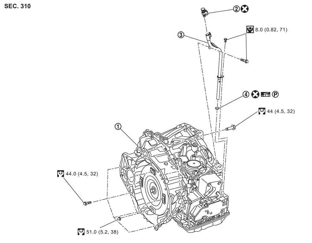
| 1. | Transaxle assembly | 2. | CVT fluid charging pipe cap | 3. | CVT fluid charging pipe |
| 4. | O-ring |
 : N·m (kg-m, in-lb)
 : N·m (kg-m, ft-lb)
 (P) : Apply petroleum jelly
 : Always replace after every disassembly.
Removal and Installation
REMOVAL
| Never Reuse These Parts | Part Code | For additional information: |
|---|---|---|
| CVT fluid charging pipe cap | 31086 | Transaxle Assembly Exploded View |
| Seal-O-ring | 31084 | Transaxle Assembly Exploded View |
WARNING:
Never remove the radiator cap when the engine is hot. Serious burns could occur from high pressure engine coolant escaping from the radiator. Wrap a thick cloth around the cap. Slowly turn it a quarter turn to allow built-up pressure to escape. Carefully remove the cap by turning it all the way.
CAUTION:
-
Perform these steps after the coolant temperature has cooled sufficiently.
-
When replacing the transaxle, perform "ADDITIONAL SERVICE WHEN REPLACING TRANSAXLE ASSEMBLY". Refer to Description.
 NOTE:
NOTE:
When removing components such as hoses, tubes/lines, etc., cap or plug openings to prevent fluid from spilling.
Remove the engine and transaxle assembly. Refer to Removal and Installation.
Remove harness bracket mounting bolt  , and then remove harness bracket
  .
.
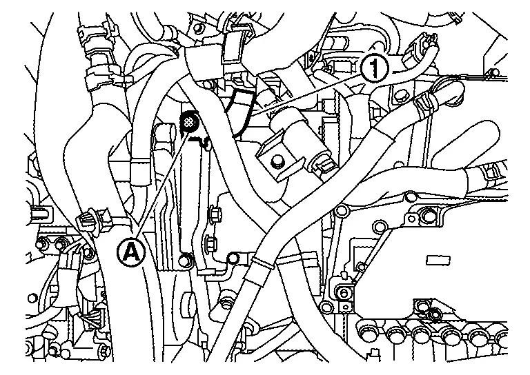
Remove harness clips .
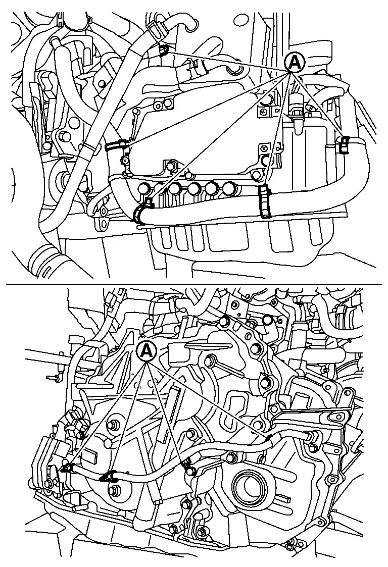
Disconnect the harness connectors.

: Shift actuator harness connector
 : Input speed sensor harness connector
 : Crankshaft position sensor harness connector
 : Terminal assembly A harness connector
 : Primary speed sensor harness connector
 : Secondary speed sensor harness connector
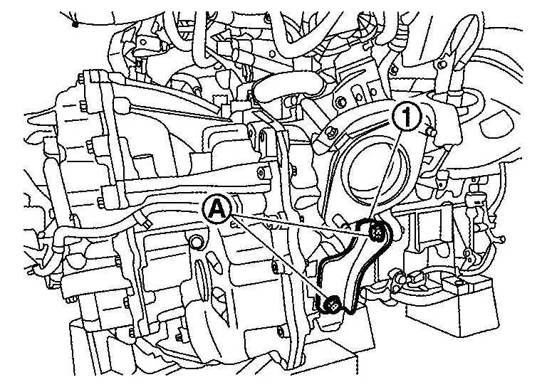
Remove catalyst support bracket mounting bolt , and then remove catalyst support bracket .
Remove water hose. Refer to Removal and Installation.
Remove starter motor. Refer to Removal and Installation.
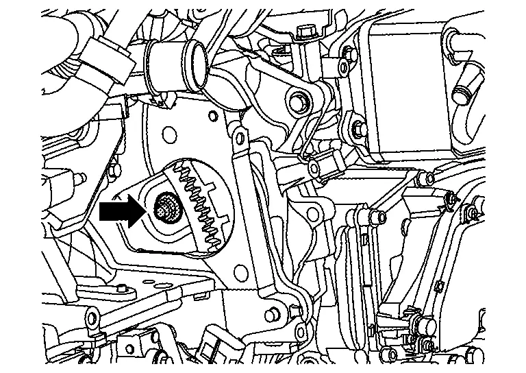
Remove tightening nuts ( 4 pieces) for drive plate and torque converter.
Remove mounting bolts for transaxle assembly and engine assembly.
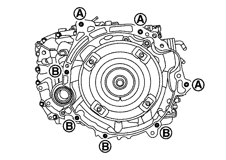
| Bolt No. | |
 |
| Insertion direction | Transaxle to engine | Engine to transaxle |
| Number of bolts | 3 | 4 |
Separate transaxle assembly from engine assembly.
Remove the following parts from transaxle assembly.
-
Air breather hose. Refer to Removal and Installation.
-
CVT fluid charging pipe.
Using paint, put matching marks on the drive plate and torque converter when removing the torque converter and drive plate fixing nuts.
INSTALLATION
Note the following, and install in the reverse order of removal.
NOTE:
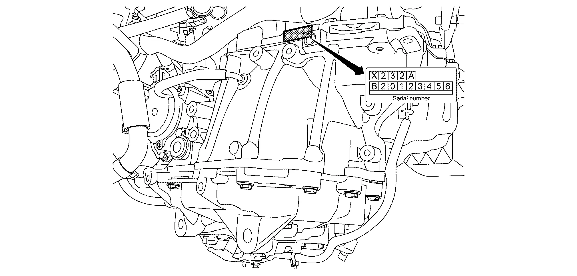
Write down the serial number of the new transaxle assembly.
CAUTION:
-
When replacing an engine or transaxle you must make sure any dowels are installed correctly.
-
During re-assembly improper alignment caused by missing dowels may cause vibration, oil leaks or breaking of drive train components.
-
Never reuse O-ring or CVT fluid charging pipe cap.
-
When turning crankshaft, turn it clockwise as viewed from the front of the engine.
-
When tightening the nuts for the torque converter while securing the crankshaft pulley bolt, be sure to confirm the tightening torque of the crankshaft pulley bolt. Refer to Exploded View.
-
After torque converter is installed to drive plate, rotate crankshaft several turns to check that CVT rotates freely without binding.
-
When installing the CVT to the engine, align the matching mark on the drive plate with the matching mark on the torque converter.
When installing transaxle assembly to the engine assembly, tighten the bolts in the sequence shown.
| Bolt No. | | |
|---|---|---|
| Insertion direction | Transaxle to engine | Engine to transaxle |
| Number of bolts | 4 | 3 |
-
When installing the drive plate to torque converter nuts, tighten them temporarily, then tighten the nuts to the specified torque.
-
Perform "ADDITIONAL SERVICE WHEN REPLACING TRANSAXLE ASSEMBLY". Refer to Description.
Inspection and Adjustment
INSPECTION BEFORE INSTALLATION
After inserting a torque converter to the CVT, check dimension (A) with in the reference value limit.
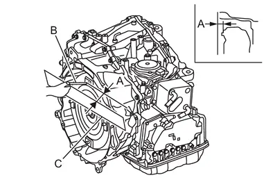
| B | : Scale |
| C | : Straightedge |
| Dimension (A) | : Refer to Torque Converter. |
INSPECTION AFTER INSTALLATION
Check the following items:
CVT fluid leakage, refer to Inspection.
For CVT position, refer to Inspection.
Start the engine and check for coolant leakage from the parts which are removed and reinstalled.
ADJUSTMENT AFTER INSTALLATION
Adjust the CVT fluid level. Refer to Adjustment.
Other materials:
Intelligent Forward Collision Warning (I-FCW)
Basic information
WARNING
Failure to follow the warnings and instructions for proper use of the I-FCW system on the Nissan Rogue could result in serious injury or death.
The I-FCW system helps alert the driver before a potential collision but cannot prevent one. The driver must remain attentive, ...
U1ca2-08 Lin Communication 3
DTC Description
DTC DETECTION LOGIC DTC No.
CONSULT screen terms
(Trouble diagnosis content) DTC detection condition
U1CA2-08
LIN communication 3
(Local interconnect network communication 3)
Diagnosis condition
Ignition switch ON
Signal (Terminal)
LIN (door motor) signal
...
Dtc/circuit Diagnosis. Door Mirror Defogger Lh
Component Function Check
CHECK DOOR MIRROR DEFOGGER LH FUNCTION
CONSULT
Ignition switch ON.
Select “Rear defogger” in “Active test” mode of "BCM".
Touch “On”.
Check that the driver side door mirror glass is getting warmer.
NOTE:
When glass is hot, never start ins ...