
Nissan Rogue (T33) 2021-Present Service Manual: Cvt Oil Warmer
Exploded View
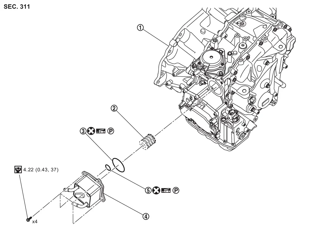
| 1. | Transaxle assembly | 2. | Oil filter | 3. | O-ring |
| 4. | CVT oil warmer | 5. | O-ring* |
 : N·m (kg-m, in-lb)
 : Always replace after every disassembly.

 : Apply petroleum jelly
*: There are one O-ring and two O-rings depending on the specifications.
Removal and Installation
REMOVAL
| Never Reuse These Parts | Part Code | For additional information: |
|---|---|---|
| Seal-O-ring | 21606Z | Exploded View |
| Seal-O-ring | 21606ZA | Exploded View |
WARNING:
Never remove the radiator cap when the engine is hot. Serious burns could occur from high pressure engine coolant escaping from the radiator. Wrap a thick cloth around the cap. Slowly turn it a quarter turn to allow built-up pressure to escape. Carefully remove the cap by turning it all the way.
CAUTION:
Perform this step when the engine is cold.
 NOTE:
NOTE:
When removing components such as hoses, tubes/lines, etc., cap or plug openings to prevent fluid from spilling.
Remove engine under cover. Refer to Removal and Installation.
Drain engine coolant. Refer to Draining.
Remove drain plug from oil pan and then drain the CVT fluid.
Remove air duct and air cleaner. Refer to Removal and Installation.
Remove CVT water hose, water control valve from CVT oil warmer. Refer to Removal and Installation.
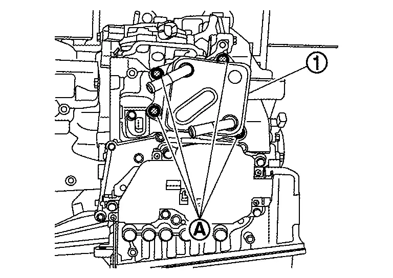
Remove CVT oil warmer mounting bolts (A) and then remove CVT oil warmer (1).
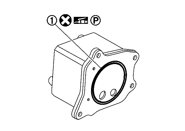
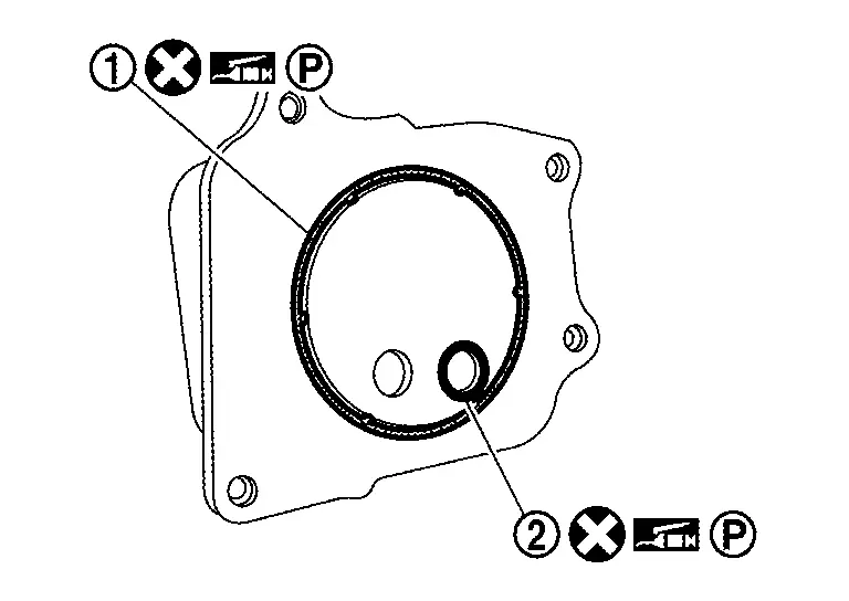
Remove O-rings (1) and (2) from CVT oil warmer.
NOTE:
There are one O-ring and two O-rings depending on the specifications. When reusing oil warmer, check the number of O-rings and use the same number of O-rings as the removed number.
-
Type with one O-ring
-
Type with two O-ring
INSTALLATION
Installation is in the reverse order of removal.
CAUTION:
-
Never reuse O-ring.
-
Apply petroleum jelly
Inspection
INSPECTION AFTER INSTALLATION
Check for CVT fluid leakage. Refer to Inspection.
Start and warm up the engine. Visually check that there is no leakage of engine coolant and CVT fluid.
ADJUSTMENT AFTER INSTALLATION
Adjust CVT fluid level. Refer to Adjustment.
Other materials:
P1148 Closed Loop Control
DTC Description
DTC DETECTION LOGICNOTE:
DTC P1148 is displayed with DTC for A/F sensor 1.
When the DTC is detected, perform the trouble diagnosis of DTC corresponding to A/F sensor 1.
DTC
CONSULT screen terms
(Trouble diagnosis content)
DTC detection condition
P1148
00
CLOS ...
Ptc Heater
Component Function Check
CHECK PTC HEATER OPERATION
Start the engine.
Operate front blower motor.
Operate temperature control dial to full hot position.
Check for warm air at discharge air outlet.
NOTE:
Engine must be cold.
Battery must be charged.
Is the i ...
How to Erase Permanent Dtc
Description
OUTLINEWhen a DTC is stored in control moduleWhen
a DTC is stored in control module and MIL is ON, a permanent DTC is
erased with MIL shutoff if the same malfunction is not detected after
performing the driving pattern for MIL shutoff three times in a raw. *1:
When the same mal ...