Nissan Rogue (T33) 2021-Present Service Manual: Water Hose
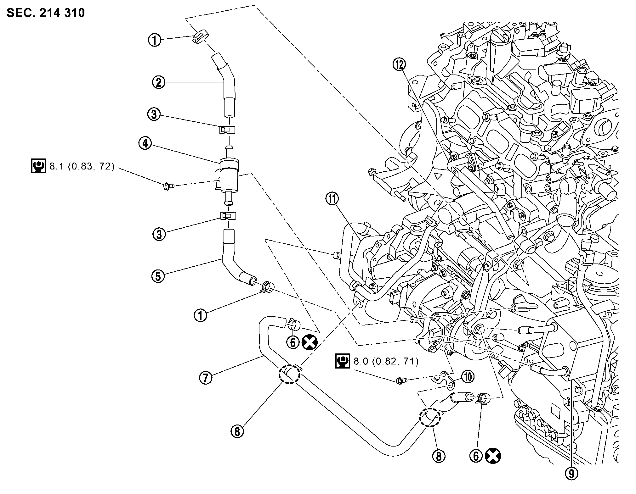
Exploded View
 |
Hose clamp |  |
CVT water hose |  |
Hose clamp |
 |
Water control valve |  |
CVT water hose |  |
Hose clamp |
 |
CVT water hose |  |
Clip |  |
CVT oil warmer |
 |
Bracket |  |
Oil cooler |  |
Water pipe 1 |
 : N·m (kg-m, in-lb)
 : Always replace after every disassembly.
Removal and Installation
REMOVAL
| Never Reuse These Parts | Part Code | For additional information |
|---|---|---|
| Clamp | 31088 | Exploded View |
WARNING:
Never remove the radiator cap when the engine is hot. Serious burns could occur from high pressure engine coolant escaping from the radiator. Wrap a thick cloth around the cap. Slowly turn it a quarter turn to allow built-up pressure to escape. Carefully remove the cap by turning it all the way.
 NOTE:
NOTE:
When removing components such as hoses, tubes/lines, etc., cap or plug openings to prevent fluid from spilling.
CAUTION:
Perform this step when the engine is cold.
Remove engine under cover. Refer to Removal and Installation.
Drain engine coolant. Refer to Draining.
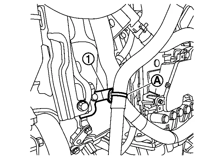
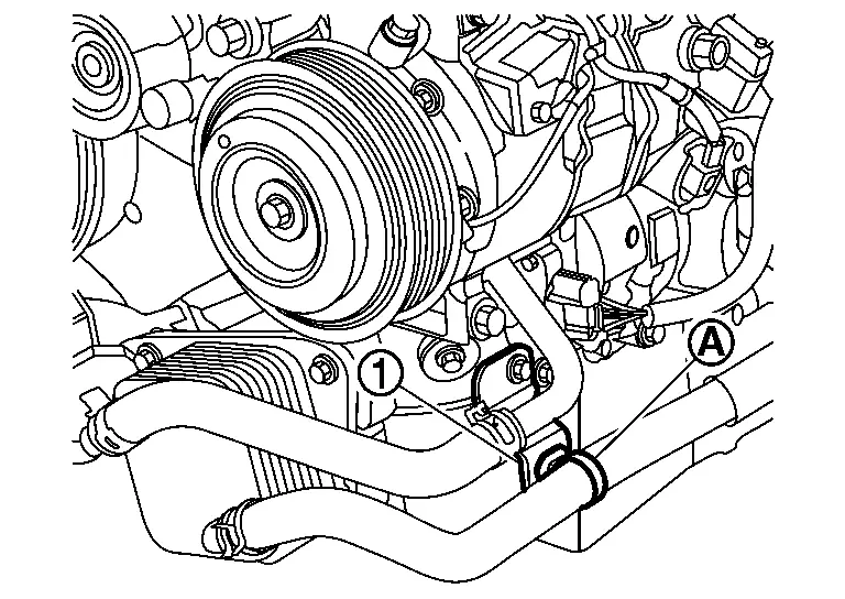
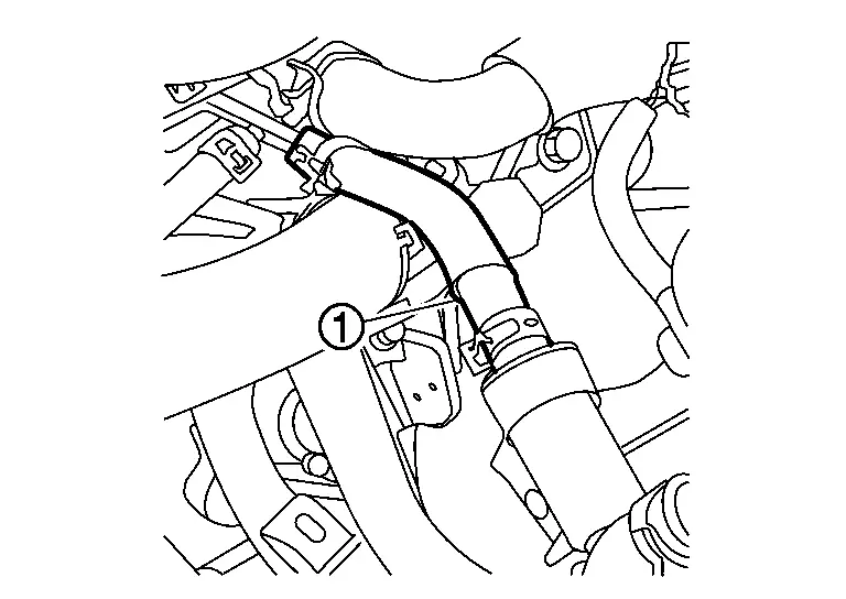
Remove clip (A) of CVT water hose from bracket (1).
Remove air cleaner and air duct. Refer to Removal and Installation.
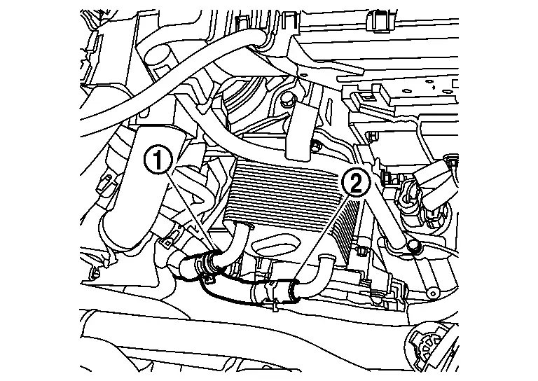
Release hose clamps (1) and (2).
CAUTION:
Never reuse hose clamps (1).
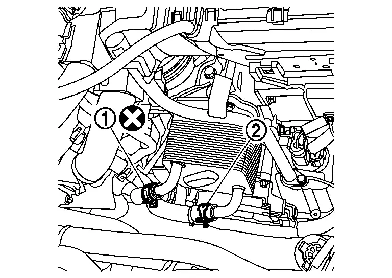
Remove CVT water hose (1) and (2) from CVT oil warmer.
Remove clip (A) of CVT water hose from bracket (1).
Release hose clamps (1).
CAUTION:
Never reuse hose clamps.
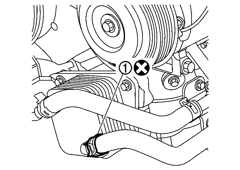
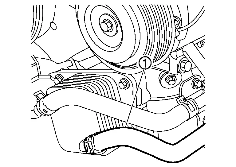
Remove CVT water hose (1) from oil cooler.
Release hose clamp (1).
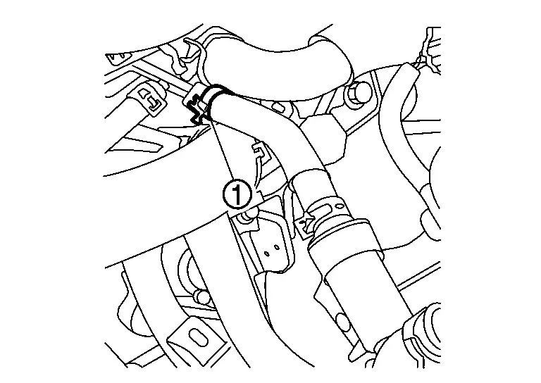
Remove CVT water hose (1) from water pipe.
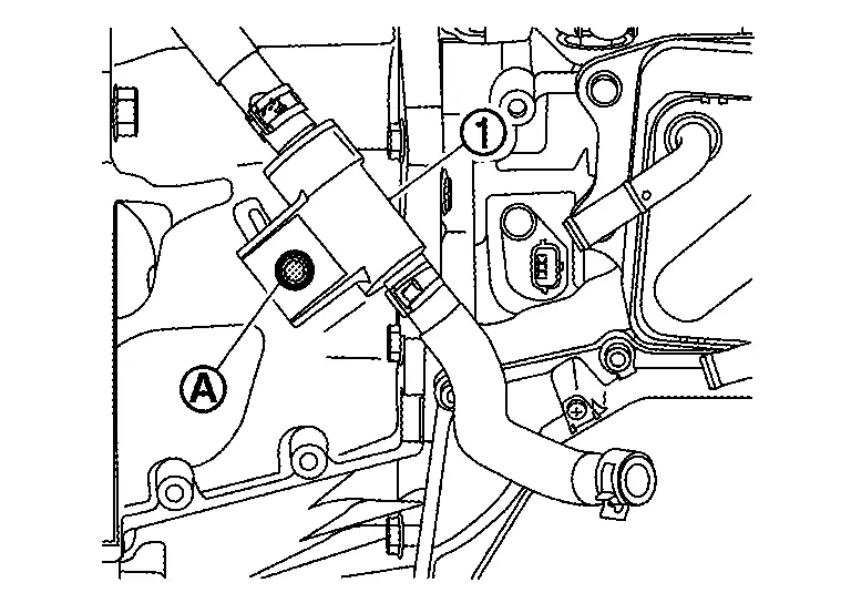
Remove water control valve mounting bolts (A) and then remove water control valve (1).
NOTE:
When disassembling water control valve, put matching marks on water control valve hoses, water control valve pipe, hose clamp and water control valve.
INSTALLATION
Note the following, and installation is in the reverse order of removal.
CAUTION:
-
Never reuse hose clamps.
-
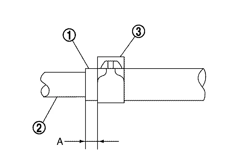
Hose clamp should not interfere with the bulge of tube.
-
Securely install the water hose clip to the bracket hole.
-
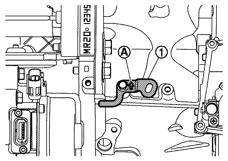
To install bracket (1) to the transalxe assembly, face the from arrow (A) of the bracket upward of the Nissan Ariya vehicle.
-
Refer to the following when installing CVT water hose.
-
Refer to the following when installing hose clamps.
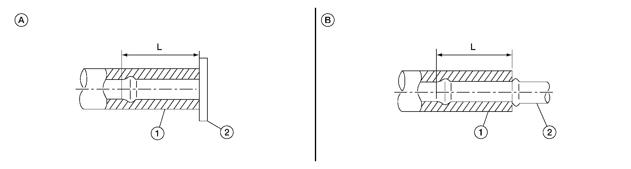
| Water hose 1. | Installation side tube 2. | Direction of paint mark | Hose insertion depth (L) |
|---|---|---|---|
| CVT water hose | Oil cooler | Rightward | B: End reaches the 2-stage bulge. |
| CVT oil warmer | Align with mark on warmer | B: End reaches the 2-stage bulge. | |
| Water control valve | CVT oil warmer | Frontward | B: End reaches the 2-stage bulge. |
| Water pipe | Upward | A: End touches the water outlet. |
| CVT water hose 1. | Installation side tube 2. | Hose clamp 3. | |
|---|---|---|---|
| Direction of tab | Clamping position (A) | ||
| CVT water hose | Oil cooler | Align with mark on water hose | 5 - 7 mm (0.20 - 0.28 in) from hose end. |
| CVT oil warmer | Align with mark on water hose | ||
| Water control valve | Water pipe | Backward | |
| CVT oil warmer | Frontward | ||
Inspection
INSPECTION AFTER REMOVAL
Water control valve
-
When coolant is cold, place dial gauge (A) on the pellet (B) of water control valve. And then measure elongation (M1) between the inlet of tube and the top of pellet.
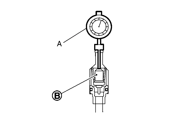
-
When elongation (M1) is 39 mm (1.54 in) or less, change the water control valve because malfunction of valve contract is expected.
-
Fully immerse the water control valve (1) in a container (A). Continue heating the water while stirring.
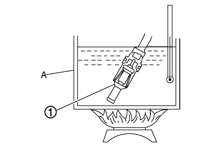
-
Continue heating water 5 minutes or more after bringing the water to a boil.
-
Quickly take the water control valve out of the hot water, and measure within 10 seconds the elongation (M2) between the inlet of tube and the top of pellet after placing dial gauge (A) on the pellet (B).
CAUTION:
Carefully handle the hot water control valve to prevent from scalding.
-
Lift amount of the pellet is calculated as the following formula; M1âM2=Lift amount
Specified lift amount: Refer to Water Control Valve .
-
When the lift amount is out of standard, replace the water control valve.
INSPECTION AFTER INSTALLATION
Start the engine, and check the joints for coolant leakage. Refer to Inspection.
Other materials:
Kr15ddt. Symptom Diagnosis. Overheating Cause Analysis
Overheating Cause Analysis
Troubleshooting Chart
Symptom Check items
Cooling system parts malfunction
Poor heat transfer
Water pump malfunction
Worn or loose drive belt
â
Thermostat stuck closed
Coolant circulation
Damaged fins
Dust contamination or rock cl ...
Awd. Periodic Maintenance
Rear Wheel Hub and Housing
Inspection
COMPONENT PARTMake sure that the mounting conditions
(looseness, backlash) of each component and component conditions (wear,
damage) are normal.WHEEL HUB ASSEMBLY (BEARING-INTEGRATED TYPE)Check the following items, and replace the part if necessary.
Mov ...
Comment utiliser l'ÃĐcran d'informations du vÃĐhicule
L'ÃĐcran d'informations du vÃĐhicule peut Être personnalisÃĐ Ã l'aide de la commande et des boutons situÃĐs sur le volant. Ces commandes du Nissan Rogue permettent de naviguer rapidement, sans quitter la route des yeux.
Commande de dÃĐfilement - permet de naviguer parmi les paramÃĻtres e ...