Nissan Rogue (T33) 2021-Present Service Manual: P0456 Evap Control System
DTC Description
DTC DETECTION LOGIC
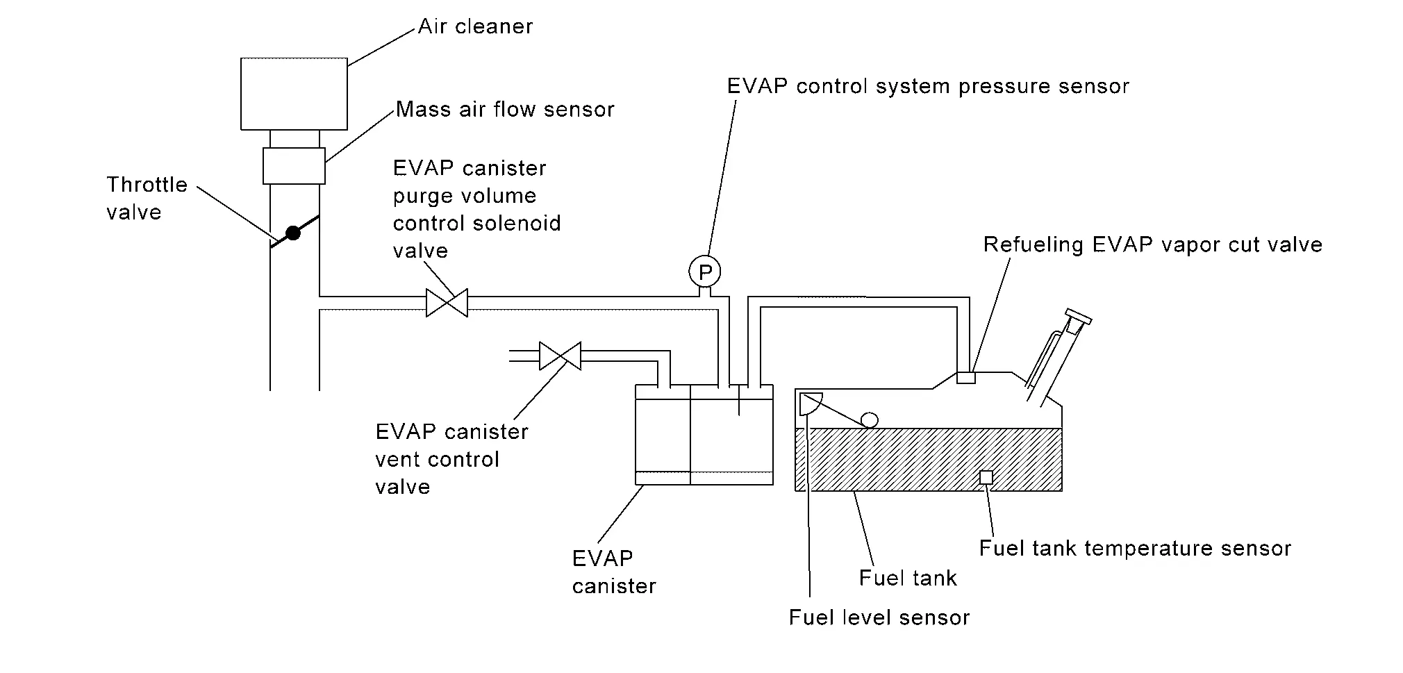
This diagnosis detects leaks in the EVAP line between fuel tank and EVAP canister purge volume control solenoid valve, using the negative pressure caused by decrease of fuel temperature in the fuel tank after turning ignition switch OFF.
If ECM judges there are no leaks, the diagnosis will be OK.
| DTC |
CONSULT screen terms (Trouble diagnosis content) |
DTC detection condition | ||
| P0456 | 00 |
EVAP VERY SML LEAK [EVAP system leak detected (very small leak)] |
Diagnosis condition | — |
| Signal (terminal) | — | |||
| Threshold |
|
|||
| Diagnosis delay time | — | |||
CAUTION:
-
Use only a genuine NISSAN fuel filler cap as a replacement. If an incorrect fuel filler cap is used, the MIL may illuminate.
-
If the fuel filler cap is not tightened properly, the MIL may illuminate.
-
Use only a genuine NISSAN rubber tube as a replacement.
POSSIBLE CAUSE
-
Incorrect fuel tank vacuum relief valve
-
Incorrect fuel filler cap used
-
Fuel filler cap remains open or does not close.
-
Foreign matter caught in fuel filler cap.
-
Leak is in line between intake manifold and EVAP canister purge volume control solenoid valve.
-
Foreign matter caught in EVAP canister vent control valve.
-
EVAP canister or fuel tank leaks
-
EVAP purge line (pipe and rubber tube) leaks
-
EVAP purge line rubber tube bent
-
Loose or disconnected rubber tube
-
EVAP canister vent control valve and the circuit
-
EVAP canister purge volume control solenoid valve and the circuit
-
Fuel tank temperature sensor
-
O-ring of EVAP canister vent control valve is missing or damaged
-
EVAP canister is saturated with water
-
EVAP control system pressure sensor
-
Refueling EVAP vapor cut valve
-
ORVR system leaks
-
Fuel level sensor and the circuit
-
Foreign matter caught in EVAP canister purge volume control solenoid valve
FAIL-SAFE
Not applicable
DTC Confirmation Procedure
PRECONDITIONING
If DTC Confirmation Procedure has been previously conducted, always perform the following before conducting the next test.
-
Turn ignition switch OFF and wait at least 10 seconds.
-
Turn ignition switch ON.
-
Turn ignition switch OFF and wait at least 10 seconds.
Do you have CONSULT?
YES>>GO TO 2.
NO>>GO TO 4.
PERFORM DTC CONFIRMATION PROCEDURE-1
 WITH CONSULT
-
Turn ignition switch ON and select “EVAP DIAG READY” in “DATA MONITOR” mode of “ENGINE” using CONSULT.
-
Start engine and wait at idle until “OFF” of “EVAP DIAG READY” changes to “ON”.
 NOTE:
NOTE:
It will take at most 2 hours until “OFF” of “EVAP DIAG READY” changes to “ON”.
-
Turn ignition switch OFF and wait at least 90 minutes.
NOTE:
Never turn ignition switch ON during 90 minutes.
-
Turn ignition switch ON and select “EVAP LEAK DIAG” in “DATA MONITOR” mode of “ENGINE” using CONSULT.
-
Check that “EVAP LEAK DIAG” indication.
Which is displayed on CONSULT?
CMPLT>>GO TO 3.
YET>>Perform DTC CONFIRMATION PROCEDURE again. GO TO 1.
PERFORM DTC CONFIRMATION PROCEDURE-2
Check 1st trip DTC.
Is 1st trip DTC detected?
YES>>Proceed to DTC Diagnosis Procedure
NO>>INSPECTION END.
PERFORM DTC CONFIRMATION PROCEDURE
 WITH GST
-
Start the engine and wait engine idle for at least 2 hours.
-
Turn ignition switch OFF and wait at least 90 minutes.
NOTE:
Never turn ignition switch ON during 90 minutes.
-
Turn ignition switch ON.
-
Check 1st trip DTC.
Is 1st trip DTC detected?
YES>>Proceed to DTC Diagnosis Procedure.
NO-1>>To check malfunction symptom before repair: Refer to Intermittent Incident.
NO-2>>Confirmation after repair: INSPECTION END
DTC Diagnosis Procedure
CHECK THE CAPLESS FLAP
Check flap of capless unit for easy opening and closing operation, when bar or nozzle with Φ20 - 21 mm (0.79 - 0.83 in) is inserted or nozzle.
Is the inspection result normal?
YES>>GO TO 2.
NO>>Replace the fuel filler tube.
CHECK THE FILLER TUBE
While applying air of 1 kPa (0.01 kg/cm2, 0.145 psi) to filler tube, check air for leakage.
Is the inspection result normal?
YES>>GO TO 3.
NO>>Replace the fuel filler tube CONDITION.
CHECK FOR EVAP LEAK
Refer to EVAP CANISTER : Periodic Maintenance.
Is there any leak in EVAP line?
YES>>Repair or replace.
NO>>GO TO 4.
CHECK EVAP CANISTER VENT CONTROL VALVE
Check the following.
-
EVAP canister vent control valve is installed properly.
Refer to Removal and Installation.
-
EVAP canister vent control valve.
Refer to Component Inspection.
Is the inspection result normal?
YES>>GO TO 5.
NO>>Repair or replace EVAP canister vent control valve and O-ring. Refer to Removal and Installation.
CHECK IF EVAP CANISTER SATURATED WITH WATER
-
Remove EVAP canister with EVAP canister vent control valve and EVAP control system pressure sensor attached.
-
Check if water will drain from the EVAP canister.
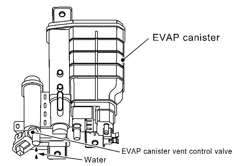
Does water drain from EVAP canister?
YES>>GO TO 6.
NO-1>>With CONSULT: GO TO 8.
NO-2>>Without CONSULT: GO TO 9.
CHECK EVAP CANISTER
Weigh the EVAP canister assembly with the EVAP canister vent control valve and EVAP control system pressure sensor attached. Refer to Removal and Installation.
The weight should be less than 2.3 kg (5.1 lb).
Is the inspection result normal?
YES-1>>With CONSULT: GO TO 8.
YES-2>>Without CONSULT: GO TO 9.
NO>>GO TO 7.
DETECT MALFUNCTIONING PART
Check the following.
-
EVAP canister for damage
-
EVAP hose between EVAP canister and Nissan Ariya vehicle frame for clogging or poor connection
>>
Repair hose or replace EVAP canister. Refer to Removal and Installation.
CHECK EVAP CANISTER PURGE VOLUME CONTROL SOLENOID VALVE OPERATION
With CONSULT
-
Disconnect vacuum hose to EVAP canister purge volume control solenoid valve at EVAP service port.
-
Start the engine and let it idle.
-
Select “PURG VOL CONT/V” in “ACTIVE TEST” mode of “ENGINE” using CONSULT.
-
Touch “Qu” on CONSULT screen to increase “PURG VOL CONT/V” opening to 100%.
-
Check vacuum hose for vacuum.
Vacuum should exist.
Is the inspection result normal?
YES>>GO TO 11.
NO>>GO TO 10.
CHECK EVAP CANISTER PURGE VOLUME CONTROL SOLENOID VALVE OPERATION
 Without CONSULT
-
Start the engine and warm it up to normal operating temperature.
-
Stop the engine.
-
Disconnect vacuum hose to EVAP canister purge volume control solenoid valve at EVAP service port.
-
Start the engine and let it idle for at least 80 seconds.
-
Check vacuum hose for vacuum when revving engine up to 2,000 rpm.
Vacuum should exist.
Is the inspection result normal?
YES>>GO TO 11.
NO>>GO TO 10.
CHECK VACUUM HOSE
Check vacuum hoses for clogging or disconnection.
Is the inspection result normal?
YES>>GO TO 11.
NO>>Repair or reconnect the hose.
CHECK EVAP CANISTER PURGE VOLUME CONTROL SOLENOID VALVE
Check the EVAP canister purge volume control solenoid valve. Refer to Component Inspection.
Is the inspection result normal?
YES>>GO TO 12.
NO>>Replace EVAP canister purge volume control solenoid valve. Refer to Exploded View.
CHECK FUEL TANK TEMPERATURE SENSOR
Check the fuel tank temperature sensor. Refer to Component Inspection.
Is the inspection result normal?
YES>>GO TO 13.
NO>>Replace fuel level sensor unit. Refer to Exploded View.
CHECK EVAP PURGE LINE
Check EVAP purge line (pipe, rubber tube, fuel tank and EVAP canister) for cracks or improper connection.
Refer to System Description.
Is the inspection result normal?
YES>>GO TO 14.
NO>>Repair or reconnect the hose.
CLEAN EVAP PURGE LINE
Clean EVAP purge line (pipe and rubber tube) using air blower.
>>
GO TO 15.
CHECK EVAP/ORVR LINE
Check EVAP/ORVR line between EVAP canister and fuel tank for clogging, kink, looseness and improper connection. For location, Refer to System Description.
Is the inspection result normal?
YES>>GO TO 16.
NO>>Repair or replace hoses and tubes.
CHECK RECIRCULATION LINE
Check recirculation line between fuel filler tube and fuel tank for clogging, kink, cracks, looseness and improper connection.
Is the inspection result normal?
YES>>GO TO 17.
NO>>Repair or replace hose, tube or fuel filler tube. Refer to Exploded View.
CHECK REFUELING EVAP VAPOR CUT VALVE
Check the refueling EVAP vapor cut valve. Refer to Component Inspection.
Is the inspection result normal?
YES>>GO TO 18.
NO>>Replace refueling EVAP vapor cut valve with fuel tank. Refer to Removal and Installation.
CHECK FUEL LEVEL SENSOR
Check the fuel level sensor. Refer to Component Function Check (FULL TFT METER) or Component Function Check (7 INCH INFORMATION DISPLAY).
Is the inspection result normal?
YES>>Replace EVAP control system pressure sensor. Refer to Removal and Installation.
NO>>Replace fuel level sensor unit. Refer to Exploded View.
Other materials:
Symptom Diagnosis. Door Does Not Lock/unlock with Door Request Switch and Intelligent Key
Description
All doors do not lock/unlock using door request switch.SYMPTOM TABLE (BOTH INTELLIGENT KEYS HAVE THE SAME SYMPTOMS) Door lock operation (remote keyless entry)
Door lock operation (request switch of front/rear/back door) or
trunk/back door open operation (opener switch of trunk/back ...
P1c90-49 Sub Starter & Generator
DTC Description
DTC DETECTION LOGIC DTC No. CONSULT screen terms (Trouble diagnosis content) DTC detection condition
P1C90-49
Sub starter & generator
(Sub starter & generator)
Diagnosis condition
Engine running at idle
Signal (terminal)
-
Threshold
Sub starte ...
If your vehicle overheats
WARNING
Never continue driving if your vehicle overheats — this can lead to engine failure or even a vehicle fire.
Never open the hood if steam is coming out.
Never remove the radiator or coolant reservoir cap when the engine is hot. Pressurized coolant can spray out and cause serious ...