Nissan Rogue (T33) 2021-Present Service Manual: Kr15ddt :: Removal and Installation
Ecm
ECM : Exploded View
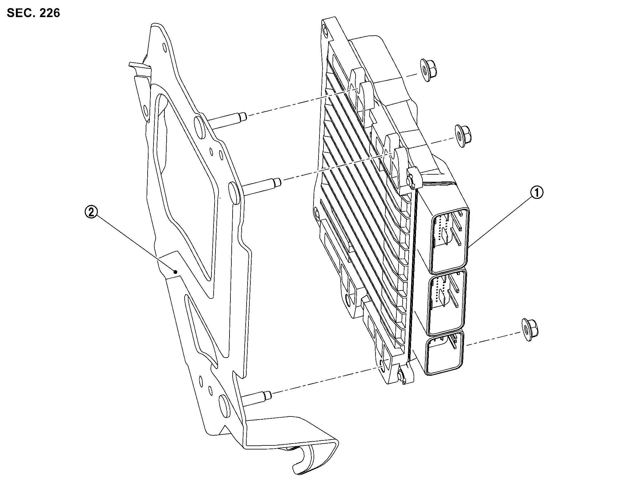
| 1. | ECM | 2. | Bracket |
ECM : Removal & Installation
CAUTION:
-
Perform ADDITIONAL SERVICE WHEN REPLACING ECM. Refer to Work Procedure.
-
When replacing the ECM, a new ECM must be used. The functions controlled by the ECM do not operate properly if an ECM from another Nissan Ariya vehicle is used.
-
Perform "ELECTRIC INTAKE VALVE TIMING CONTROL LEARNING". Refer to Work Procedure.
REMOVAL
Remove the battery. Refer to Removal and Installation.
Disconnect the harness connectors from the ECM. Refer to Harness Connector (lever locking type).
Remove the battery tray. Refer to BATTERY TRAY ; Removal and Installation.
Remove the ECM and bracket assembly.
Remove the nuts and ECM from the bracket.
INSTALLATION
Installation is in the reverse order of removal.
CAUTION:
Perform "ADDITIONAL SERVICE WHEN REPLACING ECM". Refer to Work Procedure.
Electric Intake Valve Timing Control Module
ELECTRIC INTAKE VALVE TIMING CONTROL MODULE : Exploded View
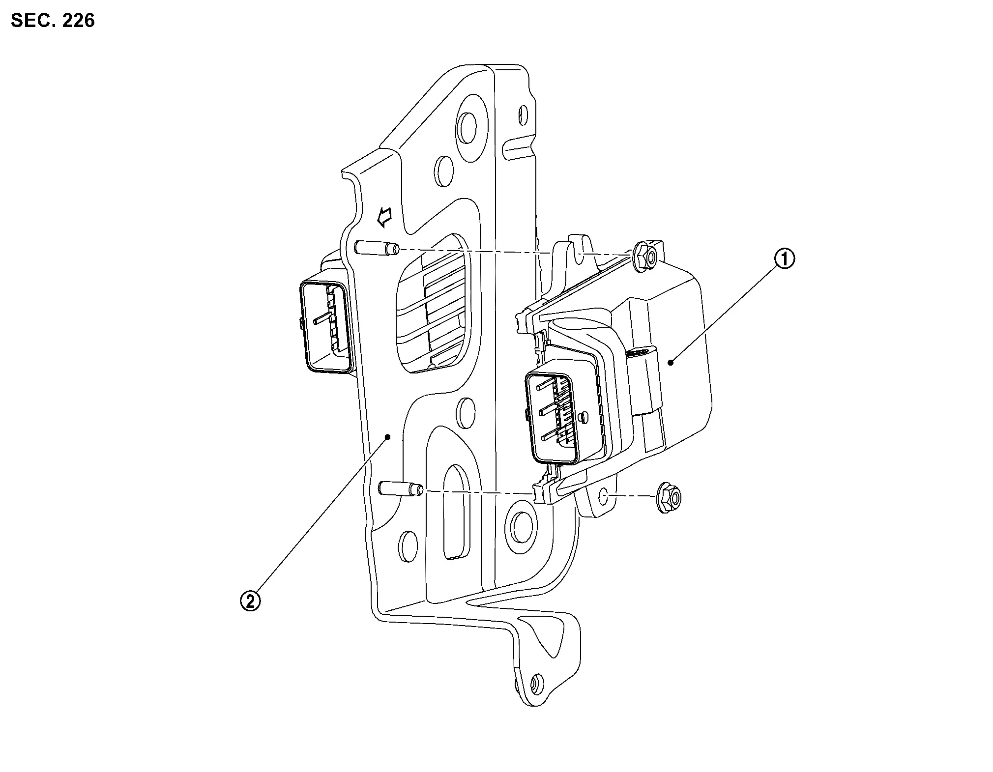
| 1. | Electric intake valve timing control module | 2. | Bracket |
ELECTRIC INTAKE VALVE TIMING CONTROL MODULE : Removal & Installation
CAUTION:
Perform "ELECTRIC INTAKE VALVE TIMING CONTROL LEARNING". Refer to Work Procedure.
REMOVAL
Disconnect negative battery terminals, then wait at least three minutes. Refer to Removal and Installation.
Partially remove the fender protector (LH). Refer to Exploded View.
Remove the relay box.
Disconnect the harness connector from the electric intake valve timing control module and VCR control module.
Remove the electric intake valve timing control module and VCR control module bracket.
Remove the electric intake valve timing control module nuts.
Remove the electric intake valve timing control module.
INSTALLATION
Installation is in the reverse order of removal.
CAUTION:
Perform "ELECTRIC INTAKE VALVE TIMING CONTROL LEARNING". Refer to Work Procedure.
Vcr Control Module
VCR CONTROL MODULE : Exploded View
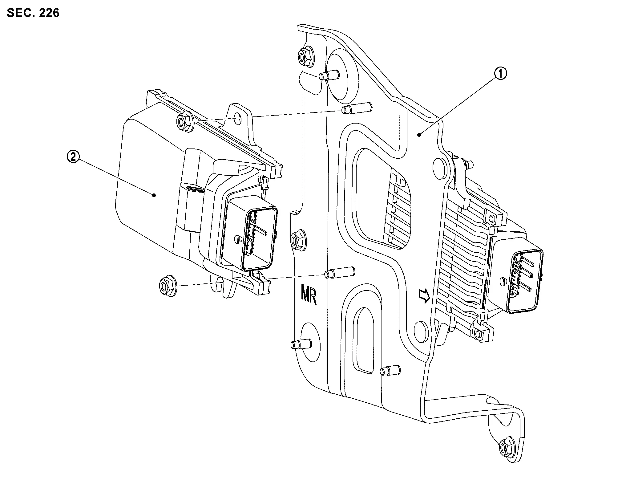
| 1. | Bracket | 2. | VCR control module |
VCR CONTROL MODULE : Removal & Installation
CAUTION:
Perform "VARIABLE COMPRESSION RATIO BASE POSITION LEARNING". Refer to Work Procedure.
REMOVAL
Disconnect negative battery terminals, then wait at least three minutes. Refer to Exploded View.
Partially remove the fender protector (LH). Refer to Exploded View.
Remove the relay box.
Disconnect the harness connector from the VCR control module.
Remove the VCR control module nuts.
Remove the VCR control module.
INSTALLATION
Installation is in the reverse order of removal.
CAUTION:
Perform "VARIABLE COMPRESSION RATIO BASE POSITION LEARNING". Refer to Work Procedure.
Start/stop Off Switch
Removal and Installation
Removal
Remove the instrument lower panel LH. Refer to Removal and Installation.
Remove screws from switch bracket and instrument panel LH.
Release pawls from switch and remove stop/start off switch from the switch bracket.
Installation
Installation is in the reverse order of removal.
Other materials:
Abs Warning Lamp
Component Function Check
CHECK ABS WARNING LAMP FUNCTION
Check that ABS warning lamp in combination meter turns ON for approximately 1 second after ignition switch is ON.
CAUTION:
Never start engine.
Is the inspection result normal?
YES>>
Inspection End
NO>>
Refer to Diagnos ...
Charge Air Cooler Electric Water Pump Relay
Component Inspection
CHECK ELECTRIC WATER PUMP RELAY
Turn ignition switch OFF.
Remove electric water pump relay.
Check the continuity between electric water pump relay terminals under the following conditions.
Terminals Conditions Continuity
and
12 V direct current supply ...
Removal/replacement of Rear Brake Pad or Rear Brake Caliper
Description
CAUTION:
When performing the following operations, always use
CONSULT, for performing ŌĆ£START BRAKE PAD REPLACEMENTŌĆØ, ŌĆ£FINISH BRAKE PAD
REPLACEMENTŌĆØ, ŌĆ£INITIALIZATION POSITION ADJUSTMENTŌĆØ of ŌĆ£Work supportŌĆØ.
Refer to Work Procedure.
├Ś: RequiredŌĆāŌĆö: not required ...