Nissan Rogue (T33) 2021-Present Service Manual: Intelligent Key Interlock Function (without Navigation System)
System Description
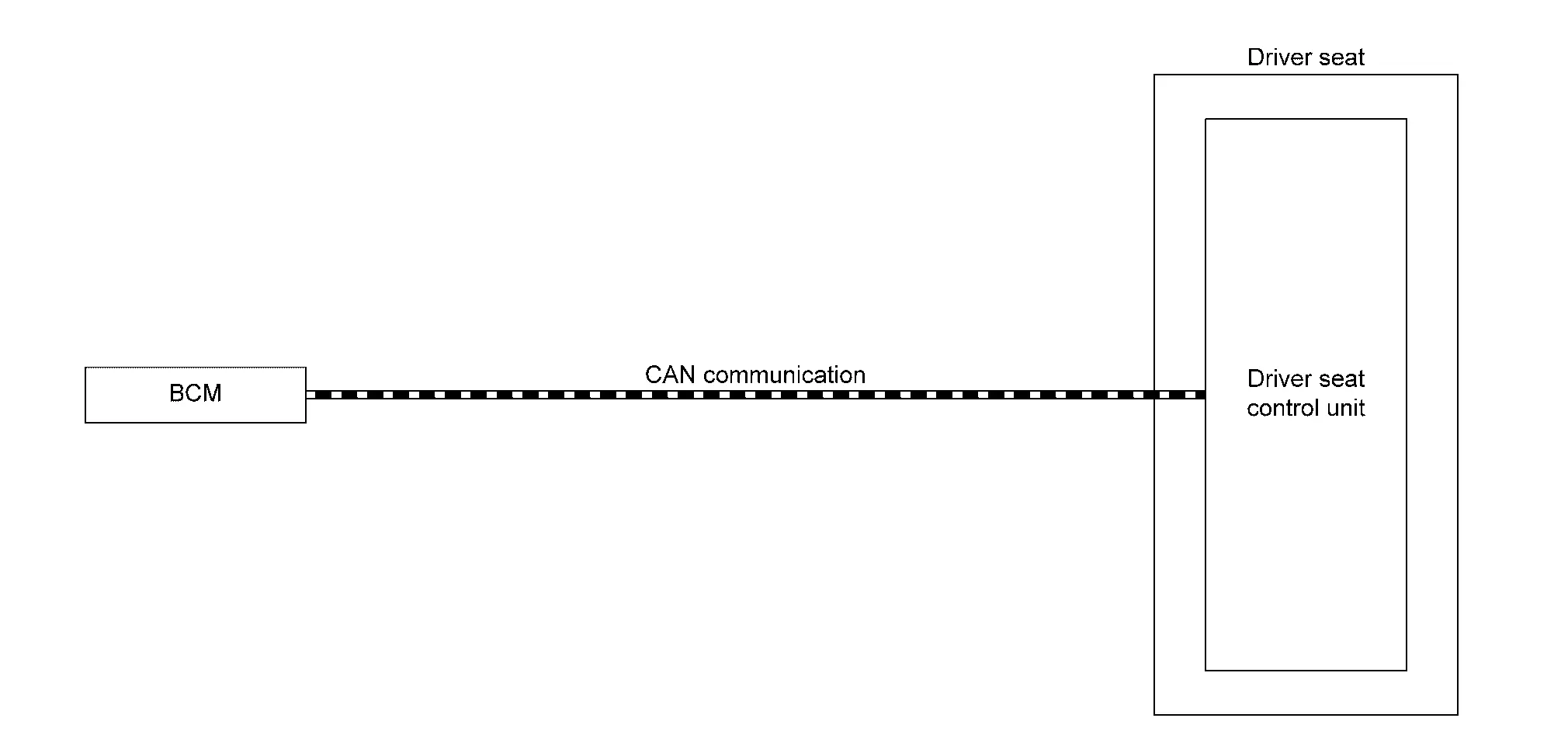
SYSTEM DIAGRAM
| Component | Function | |
|---|---|---|
| BCM |
Recognizes the following status and transmits it to driver seat control unit via CAN communication:
|
|
| Driver seat control unit | Refer to Driver Seat Control Unit. | |
DESCRIPTION
-
By associating Intelligent Key and automatic drive positioner system, the unlock operation of Intelligent Key or driver side door request switch performs memory function and entry/exit assist function.
-
Registration of Intelligent Key interlock function can register a different key ID to the driver seat control unit, one by one, for memory switch 1 and 2. A total of 2 key IDs can be registered.
-
When ignition switch is OFF, and door unlock operation is performed using Intelligent Key or driver side door request switch, driver seat automatically adjusts to a driving position other than seat sliding. Seat sliding perform return operation and are set to standby status.
-
In standby status, when ignition switch is operated from OFF to ON, return operation sets seat sliding to a registered position.
 NOTE:
NOTE:
-
When another key ID is newly registered to a key switch to which a key ID is already registered, the previously registered key ID is overwritten and becomes unusable.
-
When ignition switch signal turns ON during return operation, the operation is interrupted, ignition switch signal turns from ON to OFF, and operation restarts.
-
Further information for the Intelligent Key interlock storing procedure. Refer to Description.
Operation Procedure
-
Unlock driver door by Intelligent Key, front door request switch.
-
Operation other than memory function of seat sliding is performed. Seat sliding perform exit assist operation.
-
Ignition switch ON.
-
Driver seat will return from the exiting position to entry position.
Operation Condition
Satisfy all of the following items. The Intelligent Key interlock function is not performed if these items are not satisfied:
| Item | Request status |
|---|---|
| Ignition switch position | OFF |
| Intelligent Key interlock function setting registration | Registered |
|
Switch inputs
|
OFF (Not operated) |
| CONSULT | Not connected |
Detail Flow
| Order | Input | Output | Control unit condition |
|---|---|---|---|
| 1 |
|
— |
When the following function is performed, the driver seat control unit receives the door lock status signal and Key ID signal from BCM via CAN communication:
|
| 2 | — | — | Driver seat control unit performs the seat slide move directly to the exit assist function. Other loads move to the exit assist function after performing memory function. |
| 3 | — | — | Driver seat control unit performs the entry assist function. |
Other materials:
Telematics System. System Description
Component Parts
With 8" Color Display
Component Parts Location
No. Component Function
1.
Telematics switch
Refer to Telematics Switch.
2.
Microphone
Refer to Microphone.
3.
Air bag diagnosis sensor unit
Provides TCU with the car crash information signal via C ...
Multi Remote Ent
CONSULT Function (BCM - MULTI REMOTE ENT)
DATA MONITORNOTE:
The following table includes information (items)
inapplicable to this Nissan Ariya vehicle. For information (items)
applicable to this vehicle, refer to CONSULT display items.
Monitor Item Condition
Stop/start switch
[On/Off] ...
U0402 Can Communication
DTC Description
DTC DETECTION LOGIC DTC
CONSULT screen terms
(Trouble diagnosis content)
DTC detection condition
U0402
00
Invalid data (TCM)
(Invalid Data Received From TCM)
Diagnosis condition
Ignition switch ON
Signal (terminal)
—
Threshold
When ECM is ...