Nissan Rogue (T33) 2021-Present Service Manual: Telematics System :: System Description
Component Parts
With 8" Color Display
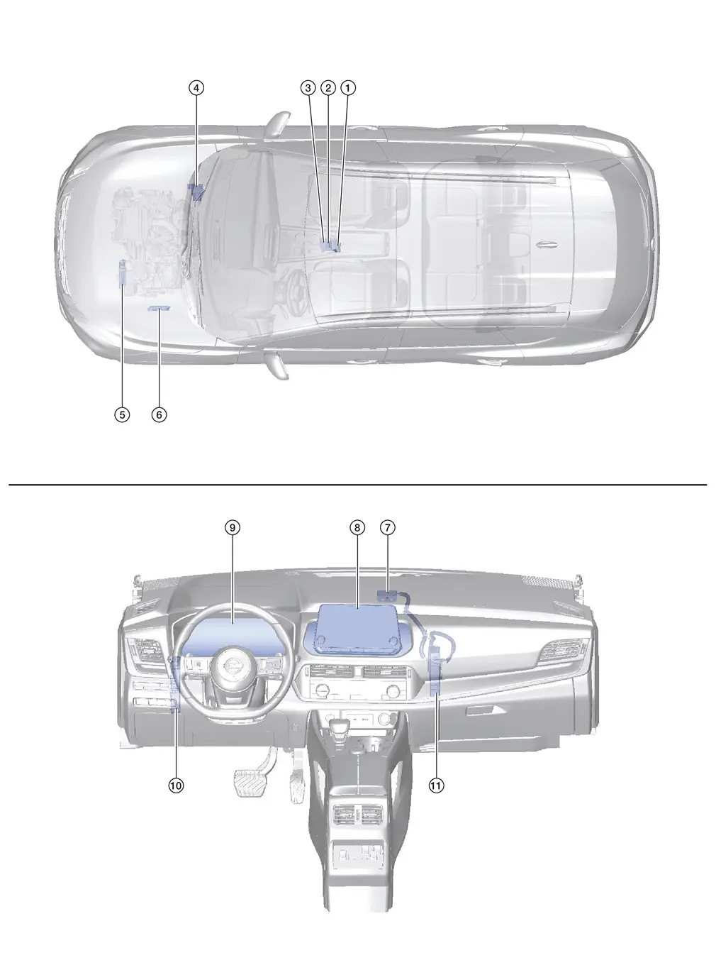
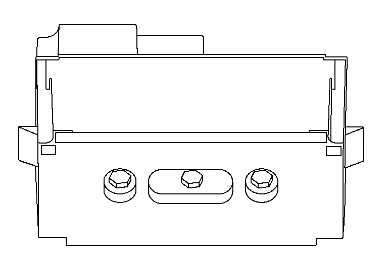
Component Parts Location
| No. | Component | Function |
|---|---|---|
| 1. | Telematics switch | Refer to Telematics Switch. |
| 2. | Microphone | Refer to Microphone. |
| 3. | Air bag diagnosis sensor unit | Provides TCU with the car crash information signal via CAN communication. |
| 4. | ABS (Anti-lock Braking System) actuator and electric unit (control unit) |
Provides TCU with the following signals via CAN communication:
|
| 5. | TCM (Transmission Control Module) | Provides AV control unit with the shift position signal via AV communication. |
| 6. | ECM (Engine Control Module) |
Provides the TCU with the following signals via CAN communication:
|
| 7. | Telematics antenna | Refer to Telematics Antenna. |
| 8. | AV control unit | Refer to AV Control Unit. |
| 9. | Combination meter |
|
| 10. | BCM (Body Control Module) |
|
| 11. | TCU | Refer to TCU. |
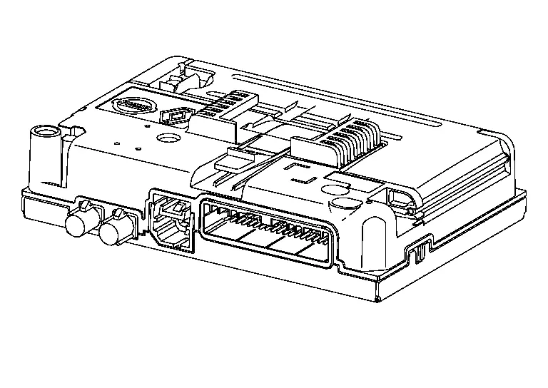
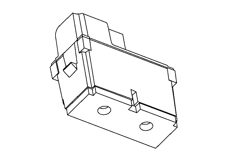
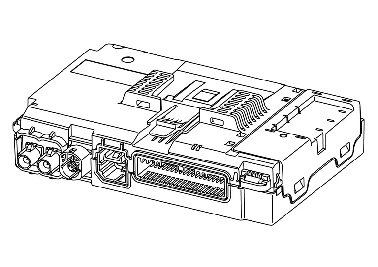
TCU
-
Telematics Control Unit (TCU) is installed in the instrument panel.
-
A Network Access Device and an eSIM are built into the TCU that facilitates the connection with the network and allow for the data to be transferred.
-
The TCU receives information request from the registered remote device (cellular handset) via SMS* using the signal provided by the telematics antenna.
*: SMS stands for Short Message Service. It is also referred to as Text Messaging, Short Mail, etc. It is the service that performs text based message communication.
-
TCU is connected to the AV control unit with the USB harness for sound signal input/output and data communication between them.
-
VIN information necessary for the TCU to ensure that the connected services are activated and initialized as required.
-
Sound signals received during an operator call are transmitted from TCU to each speaker via the AV control unit.
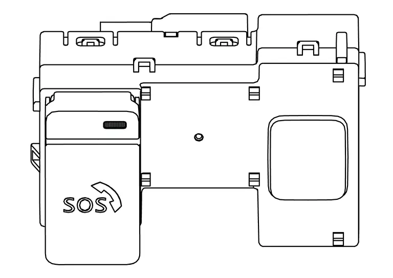
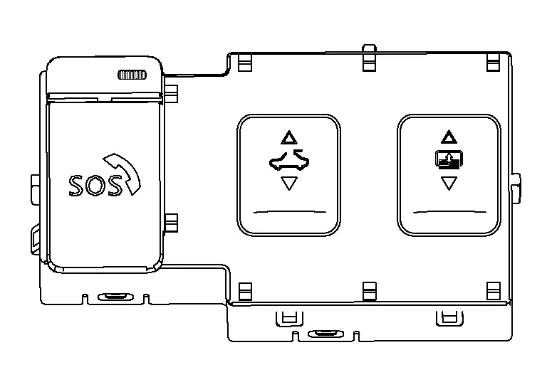
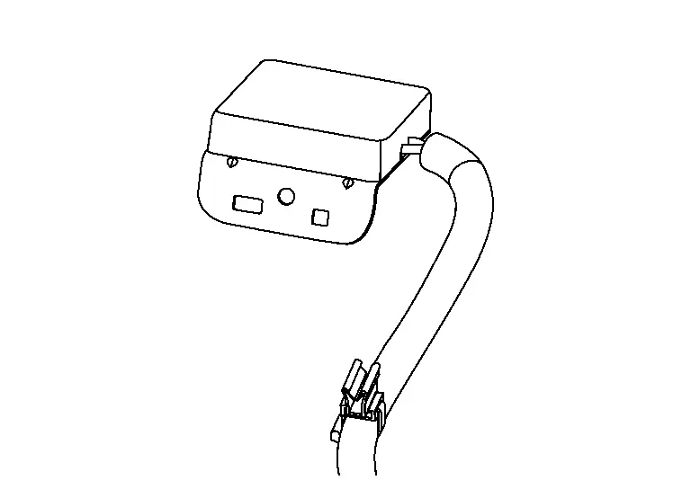
Telematics Switch
-
The Telematics switch is located on the map lamp assembly.
Without Sunroof
With Sunroof
-
The telematics switch is connected to TCU and transmits an operation signal.
-
The state of LED (ON/Blink/OFF) shows the status of SOS call.
LED ON :SOS Call available LED Blink :SOS Call in communication LED OFF :Out of service area or system error
Microphone
-
The microphone is installed on the map lamp assembly.
-
The microphone is used to talk to the operator.
-
The power is supplied from the TCU to the microphone, transmitting sound signals to the TCU.
Telematics Antenna
-
The telematics antenna is installed in the instrument panel.
-
The telematics antenna consists of the TEL antenna and GPS antenna.
With 12.3" Color Display
Component Parts Location
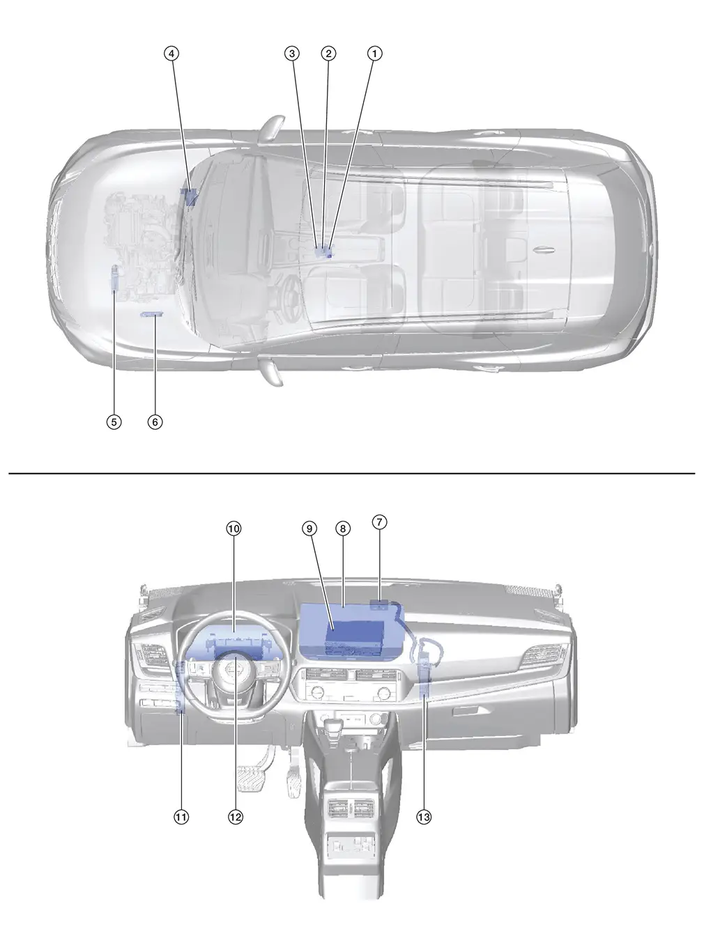
| No. | Component | Function |
|---|---|---|
| 1. | Telematics switch | Refer to Telematics Switch. |
| 2. | Microphone | Refer to Microphone. |
| 3. | Air bag diagnosis sensor unit | Provides TCU with the car crash information signal via CAN communication. |
| 4. | ABS (Anti-lock Braking System) actuator and electric unit (control unit) |
Provides TCU with the following signals via CAN communication:
|
| 5. | TCM (Transmission Control Module) | Provides AV control unit with the shift position signal via AV communication. |
| 6. | ECM (Engine Control Module) |
Provides the TCU with the following signals via CAN communication:
|
| 7. | Telematics antenna | Refer to Telematics Antenna. |
| 8. | Display unit | Refer to Display Unit. |
| 9. | AV control unit | Refer to AV Control Unit. |
| 10. | Combination meter |
|
| 11. | BCM (Body Control Module) |
|
| 12. | 8CH CAN gateway | Provides routing for the AV communication, CAN communication and ethernet communication signals. |
| 13. | TCU | Refer to TCU. |
TCU
-
Telematics Control Unit (TCU) is installed in the instrument panel.
-
A Network Access Device and an eSIM are built into the TCU that facilitates the connection with the network and allow for the data to be transferred.
-
The TCU receives information request from the registered remote device (cellular handset) via SMS* using the signal provided by the telematics antenna.
*: SMS stands for Short Message Service. It is also referred to as Text Messaging, Short Mail, etc. It is the service that performs text based message communication.
-
TCU is connected to the AV control unit with the USB harness for sound signal input/output and data communication between them.
-
VIN information necessary for the TCU to ensure that the connected services are activated and initialized as required.
-
Sound signals received during an operator call are transmitted from TCU to each speaker via the AV control unit.
Telematics Switch
-
The Telematics switch is located on the map lamp assembly.
Without Sunroof
With Sunroof
-
The telematics switch is connected to TCU and transmits an operation signal.
-
The state of LED (ON/Blink/OFF) shows the status of SOS call.
LED ON :SOS Call available LED Blink :SOS Call in communication LED OFF :Out of service area or system error
Microphone
-
The microphone is installed on the map lamp assembly.
-
The microphone is used to talk to the operator.
-
The power is supplied from the TCU to the microphone, transmitting sound signals to the TCU.
Telematics Antenna
-
The telematics antenna is installed in the instrument panel.
-
The telematics antenna consists of the TEL antenna and GPS antenna.
System
Telematics System
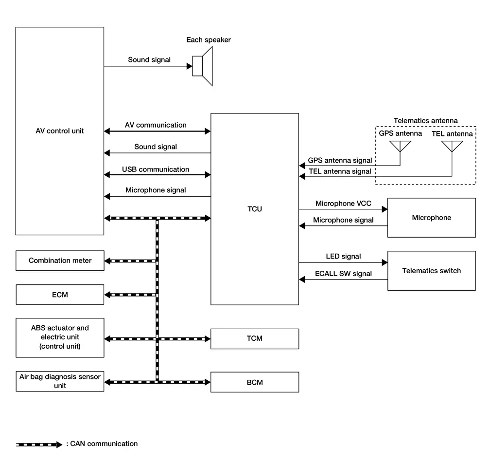
With 8" Color Display
System Description
SYSTEM DIAGRAM
TCU Input Signal (CAN Communication)
| Transmit unit | Signal name |
|---|---|
| ECM | Engine oil pressure warning lamp signal |
| Engine status signal | |
| Malfunction indicator lamp signal | |
| ABS actuator and electric unit (control unit) | ABS warning lamp signal |
| Nissan Ariya Vehicle speed signal | |
| VDC warning lamp signal | |
| Brake warning lamp signal | |
| TCM | Shift position signal |
| Combination meter | Odometer signal |
| Parking brake status signal | |
| Airbag diagnosis sensor unit | Car crush information signal |
| BCM | Front wiper request signal |
| Sleep wake up signal | |
| Door lock status signal |
TCU Output Signal (CAN Communication)
| Receive unit | Signal name |
|---|---|
| BCM | Sleep-ready signal |
| Door lock/unlock signal | |
| Panic alarm request signal | |
| Engine start request signal |
DESCRIPTION
-
NissanConnect Services provide various services to support dealing with emergencies of the subscribed Nissan Ariya vehicle and the driver. For example, in case of an illness or serious injury, you can seek support by pushing the in-Nissan Ariya vehicle telematics switch (SOS button) and connecting to the NissanConnect Services Response Center.
-
The NissanConnect Services Response Center can specify the location of the Nissan Ariya vehicle via GPS, and the information will be sent to the police or other agencies as needed.
-
Telematics Communication Unit (TCU) equipped with a radio communication terminal communicates with the NissanConnect Services Response Center via radio waves for receiving NissanConnect services.
-
With the equipment of the radio communication terminal, TCU communicates with NissanConnect Services Response Center by Packet communication*1 and SMS*2 via TEL antenna.
 NOTE:
NOTE:
-
*1: Packet communication means a communication method that data is broken down into smaller chunks for communication. The split data is called a packet and improves the efficiency of the communication circuit.
-
*2: SMS stands for Short Message Service, also known as text messaging or short mail, and provides text-based message communication services.
-
-
While communicating with the operator, data (e.g. transmission of own vehicle location) is transmitted to the NissanConnect Services Response Center by using DTMF tone signals and SMS via the radio communication module included in TCU.
-
Audio signals transmitted and received while communicating with the operator are input by microphone connected to TCU.
-
Audio signals are output from TCU via the audio data circuit connected to the AV control unit.
COMMUNICATION SIGNAL
-
TCU is connected to the AV control unit via USB communication, and it sends/receives reception data of TCU and operation signals of the AV control unit.
-
TCU is connected to each control unit via CAN communication, and it sends/receives Nissan Ariya vehicle information.
With 12.3" Color Display
System Description
SYSTEM DIAGRAM
Without Bose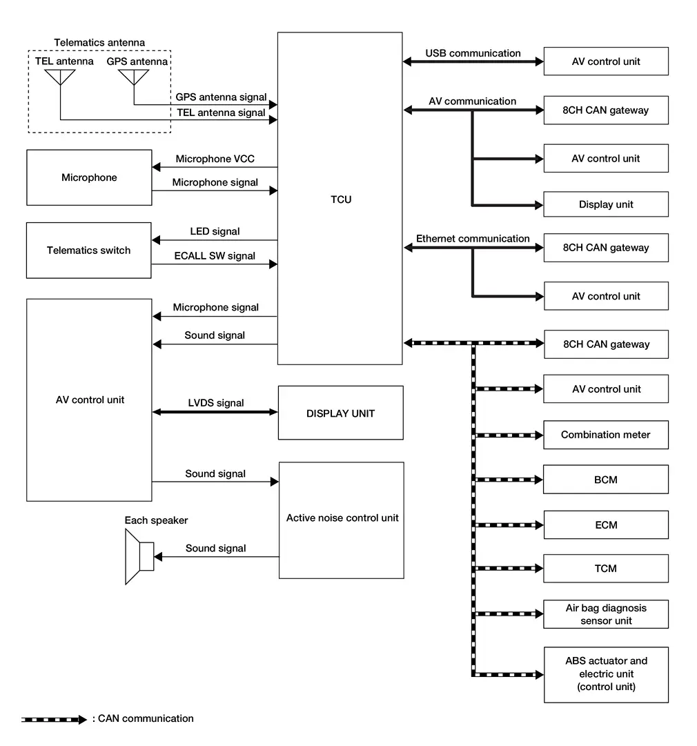
With Bose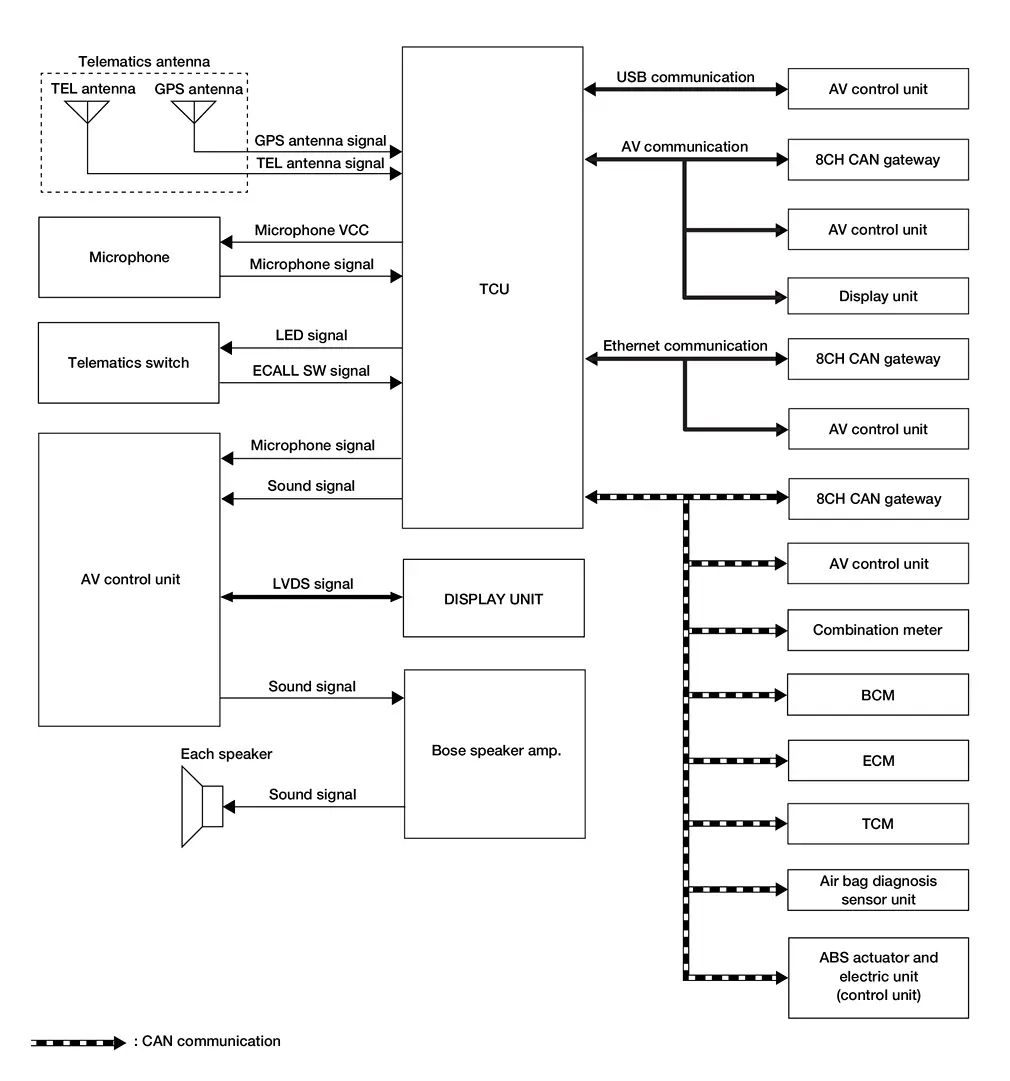
TCU Input Signal (CAN Communication)
| Transmit unit | Signal name |
|---|---|
| ECM | Engine oil pressure warning lamp signal |
| Engine status signal | |
| Malfunction indicator lamp signal | |
| ABS actuator and electric unit (control unit) | ABS warning lamp signal |
| Nissan Ariya Vehicle speed signal | |
| VDC warning lamp signal | |
| Brake warning lamp signal | |
| TCM | Shift position signal |
| Combination meter | Odometer signal |
| Parking brake status signal | |
| Airbag diagnosis sensor unit | Car crush information signal |
| BCM | Front wiper request signal |
| Sleep wake up signal | |
| Door lock status signal |
TCU Output Signal (CAN Communication)
| Receive unit | Signal name |
|---|---|
| BCM | Sleep-ready signal |
| Door lock/unlock signal | |
| Panic alarm request signal | |
| Engine start request signal |
DESCRIPTION
-
NissanConnect Services provide various services to support dealing with emergencies of the subscribed Nissan Ariya vehicle and the driver. For example, in case of an illness or serious injury, you can seek support by pushing the in-Nissan Ariya vehicle telematics switch (SOS button) and connecting to the NissanConnect Services Response Center.
-
The NissanConnect Services Response Center can specify the location of the Nissan Ariya vehicle via GPS, and the information will be sent to the police or other agencies as needed.
-
Telematics Communication Unit (TCU) equipped with a radio communication terminal communicates with the NissanConnect Services Response Center via radio waves for receiving NissanConnect services.
-
With the equipment of the radio communication terminal, TCU communicates with NissanConnect Services Response Center by Packet communication*1 and SMS*2 via TEL antenna.
NOTE:
-
*1: Packet communication means a communication method that data is broken down into smaller chunks for communication. The split data is called a packet and improves the efficiency of the communication circuit.
-
*2: SMS stands for Short Message Service, also known as text messaging or short mail, and provides text-based message communication services.
-
-
While communicating with the operator, data (e.g. transmission of own vehicle location) is transmitted to the NissanConnect Services Response Center by using DTMF tone signals and SMS via the radio communication module included in TCU.
-
Audio signals transmitted and received while communicating with the operator are input by microphone connected to TCU.
-
Audio signals are output from TCU via the audio data circuit connected to the AV control unit.
COMMUNICATION SIGNAL
-
TCU is connected to the AV control unit via USB communication, and it sends/receives reception data of TCU and operation signals of the AV control unit.
-
TCU is connected to each control unit via CAN communication, and it sends/receives Nissan Ariya vehicle information.
Diagnosis System (ivc)
Consult Function
APPLICABLE ITEMS
CONSULT performs the following items by communication with TCU.
| Diagnosis mode | Function |
|---|---|
| Self diagnosis result | The TCU self diagnosis results are displayed. |
| ECU identification | The TCU part number is displayed. |
| Work supports | Changes setting of each function. |
| Data monitor | The TCU input/output data is displayed in real time. |
| Replace ECU | Writes the Nissan Ariya vehicle specification when replacing the TCU. |
SELF DIAGNOSIS RESULT
Refer to DTC Index.
ECU IDENTIFICATION
The part number of TCU is displayed.
WORK SUPPORTS
| Item | Remarks |
|---|---|
| VIN registration | Allows the writing of the VIN to the TCU. |
| TCU ACTIVATE SETTING |
This item is displayed, but cannot be used. |
| Automatic report prevention release |
Unlock automatic report protection.
When the automatic report function of the TCU is activated, the TCU locks the automatic report function. It is necessary to release the lock on the TCU after the automatic report function of the TCU is activated. |
| Safety drive assist service setting |
This item is displayed, but cannot be used. |
| Network initial settings | Perform TCU unit communication initialization. |
DATA MONITOR
NOTE:
The table below also includes information (items) that are not applicable to this Nissan Ariya vehicle. Check the display contents of CONSULT for this vehicle adaptation information (item).
| Display item [Unit] | Condition |
|---|---|
| Zone | Regional setting of Nissan Ariya vehicle. |
|
Brand [Renault/Nissan/Infinity] |
Brand Name. |
|
Power type [Gasoline/EV/HEV/PHEV] |
Type of Nissan Ariya vehicle. |
|
Radio wave [On/Off] |
Network Access Device on Nissan Ariya vehicle setting. |
|
eUICC STATUS PIN used [Enable/Disable] |
Regional setting of Nissan Ariya vehicle. |
|
SIM status [LOCK/Unlock] |
This item is displayed, but cannot be used. |
REPLACE ECU
Writes the vehicle specification when replacing TCU.
Other materials:
U214a Can Comm Circuit
DTC Description
DTC DETECTION LOGIC DTC
CONSULT screen terms
(Trouble diagnosis content)
DTC detection condition
U214A
83
CAN comm err (AWD/4WD)
[CAN comm err (AWD/4WD)]
Diagnosis condition
Ignition switch ON
Signal (terminal)
CAN communication signal
87
T ...
Dtc/circuit Diagnosis. B203d-14 Inside Antenna
DTC Description
DTC DETECTION LOGIC DTC No.
CONSULT screen items
(Trouble diagnosis content) DTC detecting condition
B203D-14
Inside antenna
(Inside antenna)
Diagnosis condition
Work supports ŌĆ£Inside/outside antenna diagnosisŌĆØ: activated
Signal (terminal)
Inside key an ...
Informations de base
AVERTISSEMENT
Le non-respect des instructions et avertissements relatifs ├Ā lŌĆÖutilisation correcte du d├®tecteur de collision frontale intelligent du Nissan Rogue peut entra├«ner des blessures graves, voire mortelles.
Le d├®tecteur de collision frontale intelligent sert uniquement ├Ā averti ...