Nissan Rogue (T33) 2021-Present Service Manual: Telematics System :: Ecu Diagnosis Information. Tcu
Tcu
With 8" Color Display
Reference Value
VALUES ON THE DIAGNOSIS TOOL
 NOTE:
NOTE:
The following table includes information (items) inapplicable to this Nissan Ariya vehicle. For information (items) applicable to this vehicle, refer to CONSULT display items.
| Monitor Item | Condition | Value/Status | |
|---|---|---|---|
| Zone | Ignition switch ON | Display applicable regions | |
| Brand | Ignition switch ON | Nissan | |
| Power type | Ignition switch ON | Gasoline | |
| Radio wave | Ignition switch ON | On | |
| eUICC STATUS PIN used | Ignition switch ON | Enable | |
| SIM status | Ignition switch ON | Unlock | |
TERMINAL LAYOUT
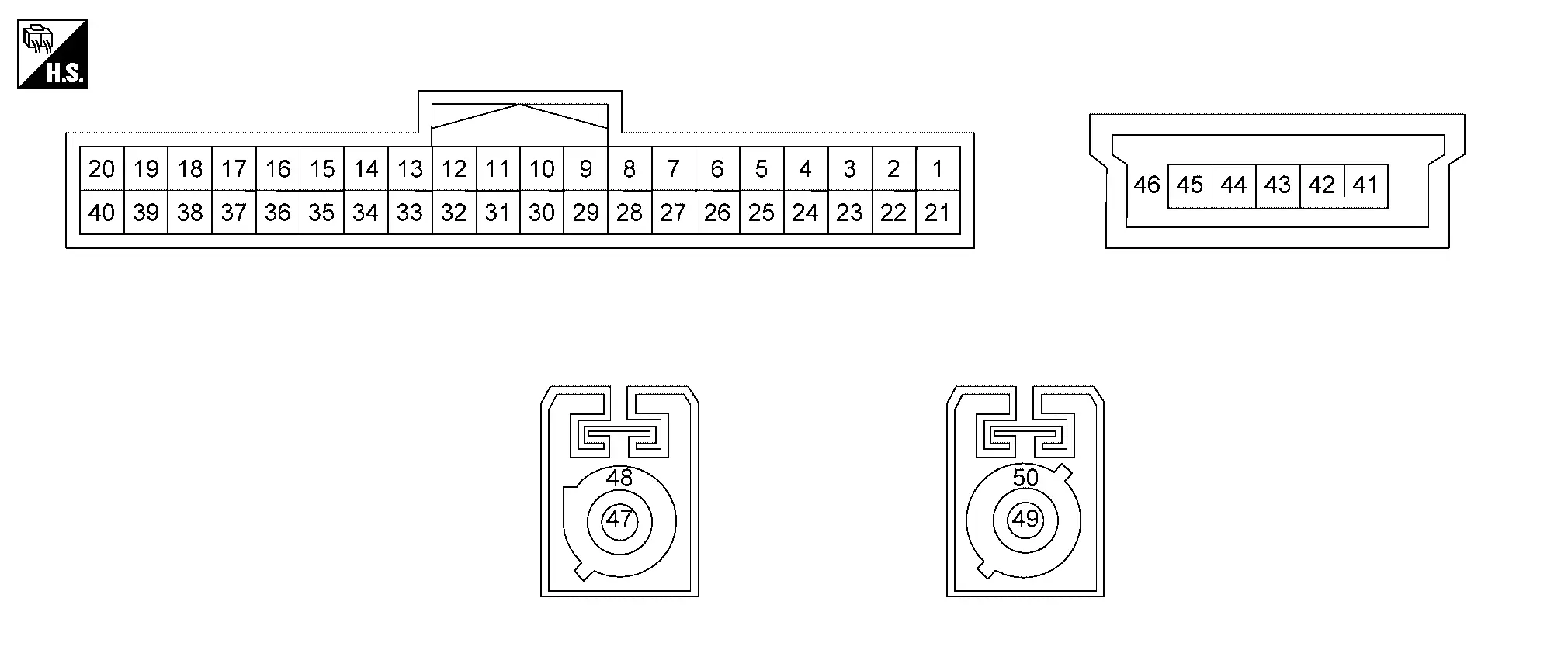
PHYSICAL VALUES
|
Terminal (Wire color) | Description | Condition | Standard |
Reference value (Approx.) | |||
|---|---|---|---|---|---|---|---|
| + | ŌĆō | Signal name | Input/Output | ||||
|
1 (R) |
Ground | Battery power supply | Input | [Ignition switch OFF] | 6.5 - 16.0 V | Battery Voltage | |
|
5 (BG)1 (R)2 |
Ground | SOS switch LED signal | Output |
[Ignition switch ON]
|
ŌĆö | 12.0 V | |
|
[Ignition switch ON]
|
ŌĆö | 0 V | |||||
|
6 (LA/SB) |
ŌĆö | CAN-High | Input/Output | ŌĆö | ŌĆö | ŌĆö | |
|
7 (LA/W)3 (LA/V)4 |
ŌĆö | CAN-Low | Input/Output | ŌĆö | ŌĆö | ŌĆö | |
|
12 (B) |
Ground | Microphone output signal | Output |
[Ignition switch ON]
|
ŌĆö |
|
|
|
17 (LG) |
16 (Shield) |
Microphone input signal | Input |
[Ignition switch ON]
|
ŌĆö |
|
|
|
18 (V) |
Ground | Microphone power supply | Output | [Ignition switch ON] | 4.0 - 5.1 V | 4.72 V | |
|
26 (LA/SB) |
ŌĆö | AV communication high | Input/Output | ŌĆö | ŌĆö | ŌĆö | |
|
27 (LA/LG) |
ŌĆö | AV communication low | Input/Output | ŌĆö | ŌĆö | ŌĆö | |
|
28 (B) |
Ground | Ground | ŌĆö | [Ignition switch ON] | ŌĆö | 0 V | |
|
29 (B) |
Ground | Ground | ŌĆö | [Ignition switch ON] | ŌĆö | 0 V | |
|
31 (LG)1 (W)2 |
32 (V)1 (B)2 |
Sound signal | Output |
[Ignition switch ON]
|
ŌĆö |
|
|
|
37 (GR) |
Ground | SOS call switch signal | Input |
[Ignition switch ON]
|
ŌĆö | 0 V | |
|
[Ignition switch ON]
|
ŌĆö | 5.0 V | |||||
|
41 (B) |
ŌĆö | USB ground | ŌĆö | ŌĆö | ŌĆö | ŌĆö | |
|
43 (G) |
ŌĆö | USB D+ signal | ŌĆö | ŌĆö | ŌĆö | ŌĆö | |
|
44 (W) |
ŌĆö | USB D- signal | ŌĆö | ŌĆö | ŌĆö | ŌĆö | |
|
45 (R) |
ŌĆö | USB V BUS signal | ŌĆö | ŌĆö | ŌĆö | ŌĆö | |
|
46 (Shield) |
ŌĆö | USB shield | ŌĆö | ŌĆö | ŌĆö | ŌĆö | |
|
47 (B) |
ŌĆö | TEL antenna signal | Input | ŌĆö | ŌĆö | ŌĆö | |
|
48 (Shield) |
ŌĆö | TEL antenna signal shield | ŌĆö | ŌĆö | ŌĆö | ŌĆö | |
|
49 (B) |
ŌĆö | GPS antenna signal | Input |
[Ignition switch ACC]
|
ŌĆö | 5.0 V | |
|
50 (Shield) |
ŌĆö | GPS antenna signal shield | ŌĆö | ŌĆö | ŌĆö | ŌĆö | |
1: USA production
2: Japan production
3: With secured gateway
4: With unsecured gateway
Fail-safe
If a malfunction occurs in the telematics, TCU performs fail-safe activation according to the detected malfunction.
| DTC | Telematics operation in fail-safe mode |
|---|---|
| B2E01-4A | Telematics system does not operate |
| B2E01-4B | |
| B2E01-96 | |
| B2E04-16 | |
| B2E08-01 | Microphone does not operate |
| B2E12-55 | TCU has not been initialized |
| B2E1B-06 | Telematics system does not operate |
| B2E1B-97 | Automatic emergency call does not operate |
| B2E32-11 | Telematics sound is not output |
| B2E32-12 | |
| B2E32-13 | |
| B2E34-11 | Telematics can not send and receive via network |
| B2E34-12 | |
| B2E34-13 | |
| B2E35-11 | Telematics can not send correct position |
| B2E35-12 | |
| B2E35-13 | |
| B2E49-06 | Remote function does not operate |
| B2E4C-06 | |
| U0079-00 | Telematics system does not operate |
| U0074-00 | |
| U2141-87 | The system using the CAN communication signal from control unit which cannot communicate does not function. |
| U2148-87 | |
| U214E-87 | |
| U2150-87 | |
| U2153-87 | |
| U2159-87 |
DTC Inspection Priority Chart
If multiple DTCs are detected simultaneously, check them one by one depending on the following DTC inspection priority chart.
| Priority | Detected items (DTC) |
|---|---|
| 1 |
|
| 2 |
|
| 3 |
|
| 4 |
|
| 5 |
|
DTC Index
Self Diagnostic Result
| DTC | Display item | Refer to |
|---|---|---|
| B2E01-4A | Internal battery | DTC Description |
| B2E01-4B | Internal battery | DTC Description |
| B2E01-96 | Internal battery | DTC Description |
| B2E04-16 | Internal battery | DTC Description |
| B2E08-01 | Microphone | DTC Description |
| B2E12-55 | Configuration | DTC Description |
| B2E1B-06 | Automatic eCall locked | DTC Description |
| B2E1B-97 | Automatic eCall locked | DTC Description |
| B2E32-11 | Audio unit | DTC Description |
| B2E32-12 | Audio unit | DTC Description |
| B2E32-13 | Audio unit | DTC Description |
| B2E34-11 | TEL antenna | DTC Description |
| B2E34-12 | TEL antenna | DTC Description |
| B2E34-13 | TEL antenna | DTC Description |
| B2E35-11 | GPS antenna | DTC Description |
| B2E35-12 | GPS antenna | DTC Description |
| B2E35-13 | GPS antenna | DTC Description |
| B2E49-06 | Remote actuator not activated | DTC Description |
| B2E4C-06 | Remote actuator with out unknown ID | DTC Description |
| U0074-00 | Control module comm Bus B Off | DTC Description |
| U0079-00 | Control module comm Bus G Off | DTC Description |
Network-DTC
| U2141-87 | CAN comm err (TCM) | DTC Description |
| U2148-87 | CAN comm err (brake control unit) | DTC Description |
| U214E-87 | CAN comm err (combination meter) | DTC Description |
| U2150-87 | CAN comm err (AIRBAG) | DTC Description |
| U2153-87 | CAN comm err (HVAC) ch1 | DTC Description |
| U2159-87 | CAN comm err (steering control unit) | DTC Description |
With 12.3" Color Display
Reference Value
VALUES ON THE DIAGNOSIS TOOL
NOTE:
The following table includes information (items) inapplicable to this Nissan Ariya vehicle. For information (items) applicable to this vehicle, refer to CONSULT display items.
| Monitor Item | Condition | Value/Status | |
|---|---|---|---|
| Zone | Ignition switch ON | Display applicable regions | |
| Brand | Ignition switch ON | Nissan | |
| Power type | Ignition switch ON | Gasoline | |
| Radio wave | Ignition switch ON | On | |
| eUICC STATUS PIN used | Ignition switch ON | Enable | |
| SIM status | Ignition switch ON | Unlock | |
TERMINAL LAYOUT
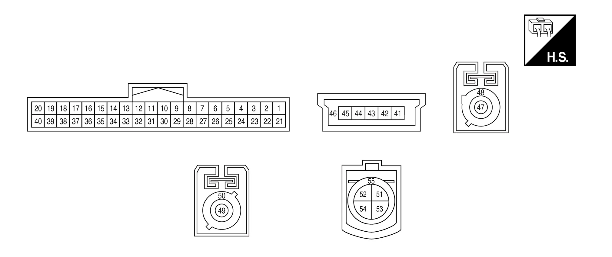
PHYSICAL VALUES
|
Terminal (Wire color) | Description | Condition | Standard |
Reference value (Approx.) | |||
|---|---|---|---|---|---|---|---|
| + | ŌĆō | Signal name | Input/Output | ||||
|
1 (R) |
Ground | Battery power supply | Input | [Ignition switch OFF] | 6.5 - 16.0 V | Battery Voltage | |
|
5 (BG)1 (R)2 |
Ground | SOS switch LED signal | Output |
[Ignition switch ON]
|
ŌĆö | 12.0 V | |
|
[Ignition switch ON]
|
ŌĆö | 0 V | |||||
|
6 (LA/SB) |
ŌĆö | CAN-High | Input/Output | ŌĆö | ŌĆö | ŌĆö | |
|
7 (LA/W)3 (LA/V)4 |
ŌĆö | CAN-Low | Input/Output | ŌĆö | ŌĆö | ŌĆö | |
|
12 (B) |
Ground | Microphone signal | Output |
[Ignition switch ON]
|
ŌĆö |
|
|
|
17 (LG) |
16 (Shield) |
Microphone signal | Input |
[Ignition switch ON]
|
ŌĆö |
|
|
|
18 (V) |
Ground | Microphone power supply | Output | [Ignition switch ON] | 4.0 - 5.1 V | 4.72 V | |
|
26 (LA/SB) |
ŌĆö | AV communication high | Input/Output | ŌĆö | ŌĆö | ŌĆö | |
|
27 (LA/LG) |
ŌĆö | AV communication low | Input/Output | ŌĆö | ŌĆö | ŌĆö | |
|
28 (B) |
Ground | Ground | ŌĆö | [Ignition switch ON] | ŌĆö | 0 V | |
|
29 (B) |
Ground | Ground | ŌĆö | [Ignition switch ON] | ŌĆö | 0 V | |
|
31 (LG)1 (W)2 |
32 (V)1 (B)2 |
Sound signal | Output |
[Ignition switch ON]
|
ŌĆö |
|
|
|
37 (GR) |
Ground | SOS call switch signal | Input |
[Ignition switch ON]
|
ŌĆö | 0 V | |
|
[Ignition switch ON]
|
ŌĆö | 5.0 V | |||||
|
41 (B) |
ŌĆö | USB ground | ŌĆö | ŌĆö | ŌĆö | ŌĆö | |
|
43 (G) |
ŌĆö | USB D+ signal | ŌĆö | ŌĆö | ŌĆö | ŌĆö | |
|
44 (W) |
ŌĆö | USB D- signal | ŌĆö | ŌĆö | ŌĆö | ŌĆö | |
|
45 (R) |
ŌĆö | USB V BUS signal | ŌĆö | ŌĆö | ŌĆö | ŌĆö | |
|
46 (Shield) |
ŌĆö | USB shield | ŌĆö | ŌĆö | ŌĆö | ŌĆö | |
|
47 (B) |
ŌĆö | TEL antenna signal | Input | ŌĆö | ŌĆö | ŌĆö | |
|
48 (Shield) |
ŌĆö | TEL antenna signal shield | ŌĆö | ŌĆö | ŌĆö | ŌĆö | |
|
49 (B) |
ŌĆö | GPS antenna signal | Input |
[Ignition switch ACC]
|
ŌĆö | 5.0 V | |
|
50 (Shield) |
ŌĆö | GPS antenna signal shield | ŌĆö | ŌĆö | ŌĆö | ŌĆö | |
|
53 (G) |
ŌĆö | Ethernet ŌłÆ | Input/Output | ŌĆö | ŌĆö | ŌĆö | |
|
54 (Y) |
ŌĆö | Ethernet + | Input/Output | ŌĆö | ŌĆö | ŌĆö | |
|
55 (Shield) |
ŌĆö | Ethernet shield | Input/Output | ŌĆö | ŌĆö | ŌĆö | |
1: USA Production
2: Japan Production
3: With secured CAN gateway
4: With unsecured CAN gateway
Fail-safe
If a malfunction occurs in the telematics, TCU performs fail-safe activation according to the detected malfunction.
| DTC | Telematics operation in fail-safe mode |
|---|---|
| B2E01-4A | Telematics system does not operate |
| B2E01-4B | |
| B2E01-96 | |
| B2E04-16 | |
| B2E08-01 | Microphone does not operate |
| B2E12-55 | TCU has not been initialized |
| B2E1B-06 | Telematics system does not operate |
| B2E1B-97 | Automatic emergency call does not operate |
| B2E32-11 | Telematics sound is not output |
| B2E32-12 | |
| B2E32-13 | |
| B2E34-11 | Telematics can not send and receive via network |
| B2E34-12 | |
| B2E34-13 | |
| B2E35-11 | Telematics can not send correct position |
| B2E35-12 | |
| B2E35-13 | |
| B2E49-06 | Remote function does not operate |
| B2E4C-06 | |
| U0079-00 | Telematics system does not operate |
| U0074-00 | |
| U2141-87 | The system using the CAN communication signal from control unit which cannot communicate does not function. |
| U2148-87 | |
| U214E-87 | |
| U2150-87 | |
| U2153-87 | |
| U2159-87 |
DTC Inspection Priority Chart
If multiple DTCs are detected simultaneously, check them one by one depending on the following DTC inspection priority chart.
| Priority | Detected items (DTC) |
|---|---|
| 1 |
|
| 2 |
|
| 3 |
|
| 4 |
|
| 5 |
|
DTC Index
Self Diagnostic Result
| DTC | Display item | Refer to |
|---|---|---|
| B2E01-4A | Internal battery | DTC Description |
| B2E01-4B | Internal battery | DTC Description |
| B2E01-96 | Internal battery | DTC Description |
| B2E04-16 | Internal battery | DTC Description |
| B2E08-01 | Microphone | DTC Description |
| B2E12-55 | Configuration | DTC Description |
| B2E1B-06 | Automatic eCall locked | DTC Description |
| B2E1B-97 | Automatic eCall locked | DTC Description |
| B2E32-11 | Audio unit | DTC Description |
| B2E32-12 | Audio unit | DTC Description |
| B2E32-13 | Audio unit | DTC Description |
| B2E34-11 | TEL antenna | DTC Description |
| B2E34-12 | TEL antenna | DTC Description |
| B2E34-13 | TEL antenna | DTC Description |
| B2E35-11 | GPS antenna | DTC Description |
| B2E35-12 | GPS antenna | DTC Description |
| B2E35-13 | GPS antenna | DTC Description |
| B2E49-06 | Remote actuator not activated | DTC Description |
| B2E4C-06 | Remote actuator with out unknown ID | DTC Description |
| U0074-00 | Control module comm Bus B Off | DTC Description |
| U0079-00 | Control module comm Bus G Off | DTC Description |
Network-DTC
| U2141-87 | CAN comm err (TCM) | DTC Description |
| U2148-87 | CAN comm err (brake control unit) | DTC Description |
| U214E-87 | CAN comm err (combination meter) | DTC Description |
| U2150-87 | CAN comm err (AIRBAG) | DTC Description |
| U2153-87 | CAN comm err (HVAC) ch1 | DTC Description |
| U2159-87 | CAN comm err (steering control unit) | DTC Description |
Other materials:
Dtc/circuit Diagnosis. Washer Fluid Level Switch Circuit
Diagnosis Procedure
CHECK WASHER FLUID LEVEL SWITCH CIRCUIT
Disconnect combination meter and washer fluid level switch connector.
Check continuity between combination meter harness connector and washer fluid level switch harness connector.
Combination meter Washer fluid level switch C ...
Side Radar (front Right) (side Radar Front Rh)
C1ec0-44 Control Unit
DTC Description
DTC DETECTION LOGIC DTC No. CONSULT screen terms (Trouble diagnosis content) DTC detection condition
C1EC0
44
Control unit
Diagnosis condition
When ignition switch is ON.
Signal (terminal)
ŌĆö
Threshold
If side radar front RH ...
Rear Propeller Shaft: Cvj-Cvj-C. Precaution. Precautions
Precautions
Precaution for Supplemental Restraint System (SRS) "AIR BAG" and "SEAT BELT PRE-TENSIONER"
The Supplemental Restraint System such as ŌĆ£AIR BAGŌĆØ and ŌĆ£SEAT BELT
PRE-TENSIONERŌĆØ, used along with a front seat belt, helps to reduce the
risk or severity of injury to the driver and ...