
Nissan Rogue (T33) 2021-Present Service Manual: Intelligent Key Interlock Function (with Navigation System)
System Description
SYSTEM DIAGRAM
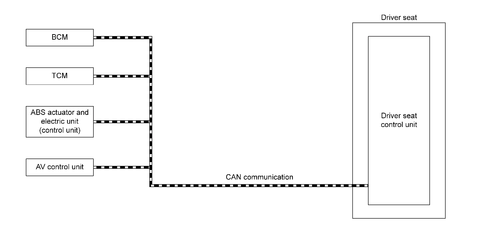
| Component | Function | |
|---|---|---|
| BCM |
Recognizes the following status and transmits it to driver seat control unit via CAN communication:
|
|
| TCM | TCM transmits the shift position signal to driver seat control unit via CAN communication. | |
| ABS actuator and electric unit (control unit) | ABS actuator and electric unit (control unit) transmits the Nissan Ariya vehicle speed signal to driver seat control unit via CAN communication. | |
| AV control unit | Intelligent Key interlock function can be set on the navigation display. | |
| Driver seat control unit | Refer to Driver Seat Control Unit. | |
DESCRIPTION
-
When ignition switch is OFF, and door unlock operation is performed using Intelligent Key or driver side door request switch, driver seat automatically adjusts to a driving position other than seat sliding. Seat sliding perform return operation and are set to standby status.
-
In standby status, when ignition switch is operated from OFF to ON, return operation sets seat sliding to a registered position.
 NOTE:
NOTE:
When ignition switch signal turns ON during return operation, the operation is interrupted, ignition switch signal turns from ON to OFF, and operation restarts.
Operation Procedure
-
Unlock driver door by Intelligent Key, front door request switch.
-
Operation other than memory of seat sliding is performed. Seat sliding perform exit assist operation.
-
Ignition switch ON.
-
Driver seat will return from the exiting position to entry position.
Operation Condition
Satisfy all of the following items. The Intelligent Key interlock function is not performed if these items are not satisfied:
| Item | Request status |
|---|---|
| Ignition switch position | OFF |
| Log-in function setting registration | Registered |
|
Switch inputs
|
OFF (Not operated) |
| CONSULT | Not connected |
| Nissan Ariya Vehicle speed | 0 MPH (0 km/h) |
Detail Flow
| Order | Input | Output | Control unit condition |
|---|---|---|---|
| 1 |
|
— |
When the following function is performed, the driver seat control unit receives the door lock status signal and Key ID signal from BCM via CAN communication:
|
| 2 | — | — | Driver seat control unit performs the seat slide move directly to the exit assist function. Other loads move to the exit assist function after performing log-in function. |
| 3 | — | — | Driver seat control unit performs the entry assist function. |
Other materials:
Motion-activated liftgate
Basic information
The Nissan Rogue liftgate can be opened using a quick forward kicking motion beneath the center area of the rear bumper.
The kick motion sensor a is located behind the bumper. When your foot moves under and away from the detection area b while carrying the Intelligent Key, ...
Automatic Emergency Braking. Ecu Diagnosis Information
Adas Control Unit 2
List of ECU Reference
ECU Reference
ADAS control unit 2 (Without ProPILOT Assist 2.1)
Reference Value
Fail-safe (ADAS Control Unit 2)
DTC Inspection Priority Chart
DTC Index
ADAS control unit 2 (With ProPILOT Assist 2.1)
Reference Value
Fail- ...
P11a9 Vcr Target Angle
DTC Description
DTC DETECTION LOGIC DTC
CONSULT screen terms
(Trouble diagnosis content)
DTC detection condition
P11A9
00
VCR target angle
(Variable compression ratio target angle)
Diagnosis condition
Engine running at idle
Signal (terminal)
—
Threshold
...