Nissan Rogue (T33) 2021-Present Service Manual: Information Display (combination Meter)
Driving Position Memory
DESIGN/PURPOSE
Display registration status of driving position.
| Display pattern | Symbol | Message |
|---|---|---|
| A |
|
Press button to save driving position |
| B |
|
Driving position saved |
| C |
|
Driving position saved |


SYSTEM DIAGRAM
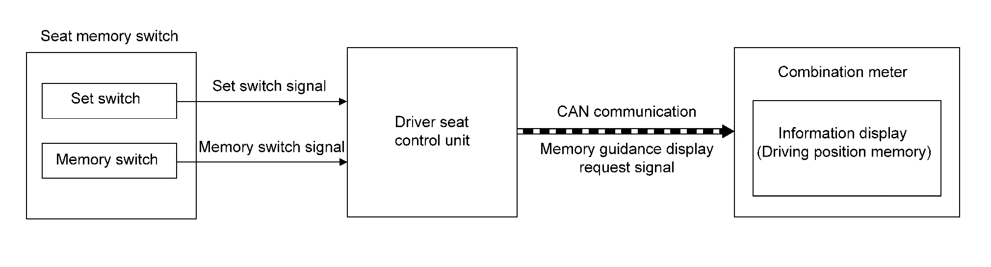
SIGNAL PATH
-
The driver seat control unit transmits a memory guidance display request signal (guidance display) to the combination meter for 5 seconds via CAN communication when the set switch is pressed.
-
Combination meter displays the guidance (display pattern A) in the information display when it receives the memory guidance display request signal (guidance display) when the ignition switch is ON.
-
When press memory switch-1 within 5 seconds after pressing set switch, driver seat control unit registered driving position to memory 1 and transmits memory guidance display request signal (memory 1 registration completion display) to the combination meter for 5 seconds via CAN communication.
-
Combination meter displays the memory 1 registration completed (display pattern B) in the information display when it receives the memory guidance display request signal (memory 1 registration completion display) when the ignition switch is ON.
-
When press memory switch-2 within 5 seconds after pressing set switch, driver seat control unit registered driving position to memory 2 and transmits memory guidance display request signal (memory 2 registration completion display) to the combination meter for 5 seconds via CAN communication.
-
Combination meter displays the memory 2 registration completed (display pattern C) in the information display when it receives the memory guidance display request signal (memory 2 registration completion display) when the ignition switch is ON.
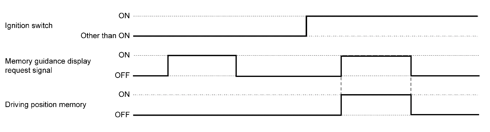
WARNING/INDICATOR OPERATING CONDITION
When all of the following conditions are satisfied:
-
Ignition switch ON
-
Memory guidance display request signal is ON
WARNING/INDICATOR CANCEL CONDITION
When any of the following conditions are satisfied:
-
Ignition switch other than ON
-
Memory guidance display request signal is OFF
TIMING CHART
Other materials:
Symptom Diagnosis. Manual Function Does Not Operate
All Component
Diagnosis Procedure
CHECK DRIVER SEAT CONTROL UNIT POWER SUPPLY AND GROUND CIRCUIT
Check driver seat control unit power supply and ground circuit. Refer to Diagnosis Procedure.
Is the inspection result normal?
YES>>
GO TO 2.
NO>>
Repair or replace the malfunctioni ...
Symptom Diagnosis. Wiper Deicer Does Not Operate
Diagnosis Procedure
CHECK WIPER DEICER RELAY
Check wiper deicer relay.
Refer to Component Inspection.
Is the inspection result normal?
YES>>
GO TO 2.
NO>>
Repair or replace the malfunctioning parts.
CHECK WIPER DEICER
Check wiper deicer.
Refer to Component Function Check.
I ...
U1321-55 Configuration Unfinished
DTC Description
DTC DETECTION LOGIC DTC No.
CONSULT screen terms
(Trouble diagnosis content) DTC detection condition
U1321–55
Config unfinished
(Configuration unfinished)
Diagnosis condition
When ignition switch is ON
Signal (terminal)
—
Threshold
Configuration ...