Nissan Rogue (T33) 2021-Present Service Manual: Heated Oxygen Sensor 2
Component Function Check
PERFORM COMPONENT FUNCTION CHECK-1
 Without CONSULT
-
Start engine and warm it up to normal operating temperature.
-
Turn ignition switch OFF and wait at least 10 seconds.
-
Start engine and keep the engine speed between 3,500 and 4,000 rpm for at least 1 minute under no load.
-
Let engine idle for 1 minute.
-
Check the voltage between ECM harness connector and ground as per the following condition.
ECM Condition Voltage Connector + ŌłÆ Terminal F71 92 97 Revving up to 4,000 rpm under no load at least 10 times The voltage should be above 0.71 V at least once during this procedure.
Is the inspection result normal?
YES>>INSPECTION END
NO>>GO TO 2.
PERFORM COMPONENT FUNCTION CHECK-2
Check the voltage between ECM harness connector and ground as per the following condition.
| ECM | Condition | Voltage | ||
|---|---|---|---|---|
| Connector | + | ŌłÆ | ||
| Terminal | ||||
| F71 | 92 | 97 | Keeping engine speed at idle for 10 minutes | The voltage should be above 0.71 V at least once during this procedure. |
Is the inspection result normal?
YES>>INSPECTION END
NO>>GO TO 3.
PERFORM COMPONENT FUNCTION CHECK-3
Check the voltage between ECM harness connector and ground as per the following condition.
| ECM | Condition | Voltage | ||
|---|---|---|---|---|
| Connector | + | ŌłÆ | ||
| Terminal | ||||
| F71 | 92 | 97 | Coasting from 80 km/h (50 MPH) in D position | The voltage should be above 0.71 V at least once during this procedure. |
Is the inspection result normal?
YES>>INSPECTION END
NO>>Refer to Component Inspection.
Component Inspection
INSPECTION START
Do you have CONSULT?
Do you have CONSULT?
YES>>GO TO 2.
NO>>GO TO 3.
CHECK HEATED OXYGEN SENSOR 2
 With CONSULT
-
Turn ignition switch ON and select ŌĆ£DATA MONITORŌĆØ mode of ŌĆ£ENGINEŌĆØ using CONSULT.
-
Start engine and warm it up to normal operating temperature.
-
Turn ignition switch OFF and wait at least 10 seconds.
-
Start engine and keep the engine speed between 3,500 and 4,000 rpm for at least 1 minute under no load.
-
Let engine idle for 1 minute.
-
Select ŌĆ£FUEL INJECTIONŌĆØ in ŌĆ£ACTIVE TESTŌĆØ mode of ŌĆ£ENGINEŌĆØ using CONSULT, and select ŌĆ£HO2S2 (B1)ŌĆØ as the monitor item with CONSULT.
-
Check ŌĆ£HO2S2 (B1)ŌĆØ at idle speed when adjusting ŌĆ£FUEL INJECTIONŌĆØ to ┬▒ 25%.
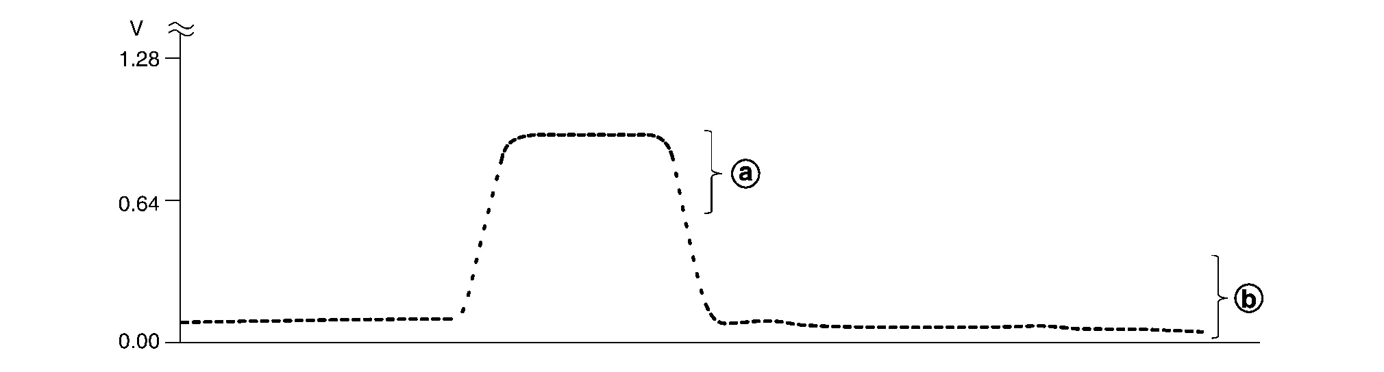
ŌĆ£HO2S2 (B1)ŌĆØ should be above
 0.71 V at least once when the ŌĆ£FUEL INJECTIONŌĆØ is + 25%.
ŌĆ£HO2S2 (B1)ŌĆØ should be below
 0.18 V at least once when the ŌĆ£FUEL INJECTIONŌĆØ is ŌłÆ 25%.
Is the inspection result normal?
YES>>INSPECTION END
NO>>GO TO 6.
CHECK HEATED OXYGEN SENSOR 2-1
Without CONSULT
-
Start engine and warm it up to normal operating temperature.
-
Turn ignition switch OFF and wait at least 10 seconds.
-
Start engine and keep the engine speed between 3,500 and 4,000 rpm for at least 1 minute under no load.
-
Let engine idle for 1 minute.
-
Check the voltage between ECM harness connector and ground as per the following condition.
ECM Condition Voltage Connector + ŌłÆ Terminal F71 92 97 Revving up to 4,000 rpm under no load at least 10 times The voltage should be above 0.71 V at least once during this procedure.
The voltage should be below 0.18 V at least once during this procedure.
Is the inspection result normal?
YES>>INSPECTION END
NO>>GO TO 4.
CHECK HEATED OXYGEN SENSOR 2-2
Check the voltage between ECM harness connector and ground as per the following condition.
| ECM | Condition | Voltage | ||
|---|---|---|---|---|
| Connector | + | ŌłÆ | ||
| Terminal | ||||
| F71 | 92 | 97 | Keeping engine speed at idle for 10 minutes |
The voltage should be above 0.71 V at least once during this procedure. The voltage should be below 0.18 V at least once during this procedure. |
Is the inspection result normal?
YES>>INSPECTION END
NO>>GO TO 5.
CHECK HEATED OXYGEN SENSOR 2-3
Check the voltage between ECM harness connector and ground as per the following condition.
| ECM | Condition | Voltage | ||
|---|---|---|---|---|
| Connector | + | ŌłÆ | ||
| Terminal | ||||
| F71 | 92 | 97 | Coasting from 80 km/h (50 MPH) in D position |
The voltage should be above 0.71 V at least once during this procedure. The voltage should be below 0.18 V at least once during this procedure. |
Is the inspection result normal?
YES>>INSPECTION END
NO>>GO TO 6.
REPLACE HEATED OXYGEN SENSOR 2
Replace heated oxygen sensor 2. Refer to Exploded View.
CAUTION:
-
Discard any sensor which has been dropped from a height of more than 0.5 m (19.7 in) onto a hard surface such as a concrete floor; use a new one.
-
Before installing new sensor, clean exhaust system threads using Oxygen Sensor Thread Cleaner [commercial service tool (NI-43897-18 or NI-43897-12)] and approved Anti-seize Lubricant (commercial service tool).
>>
INSPECTION END
Other materials:
Component Parts
Automatic Air Conditioning System
Component Parts Location
A.
Instrument panel
B.
Left front of Nissan Ariya vehicle
C.
Right side of blower unit assembly
D.
Right side of heater and cooling unit assembly
E.
Left side of heater and cooling unit assembly
...
Fuel Injector Relay
Component Inspection
CHECK FUEL INJECTOR RELAY
Turn ignition switch OFF.
Remove fuel injector relay. Refer to Component Parts Location.
Check the continuity between fuel injector relay terminals as per the following conditions.
Fuel injector relay Condition Continuity
+ ŌłÆ
...
├ētiquette des pneus
Exemple
Informations de base
La l├®gislation f├®d├®rale impose aux fabricants de pneus dŌĆÖapposer sur le flanc de chaque pneu des informations normalis├®es et clairement lisibles. Ces marquages, pr├®sents sur les pneus du Nissan Rogue, permettent dŌĆÖidentifier les caract├®ristiques essenti ...