Nissan Rogue (T33) 2021-Present Service Manual: Fuel Pressure Check
Work Procedure
FUEL PRESSURE RELEASE
FUEL PRESSURE RELEASE
 With CONSULT
-
Turn ignition switch ON.
-
Perform ãENGINEã in ãWORK SUPPORTã mode with CONSULT.
-
Start the engine.
-
After engine stalls, crank it two or three times to release all fuel pressure.
-
Turn ignition switch OFF.
 Without CONSULT
-
Remove fuel pump fuse located in IPDM E/R.
-
Start the engine.
-
After engine stalls, crank it two or three times to release all fuel pressure.
-
Turn ignition switch OFF.
-
Reinstall fuel pump fuse after servicing fuel system.
>>
INSPECTION END
FUEL PRESSURE CHECK
FUEL PRESSURE CHECK
-
Release fuel pressure.
-
Connect fuel hose for fuel pressure check (B) to fuel pressure gauge (A). Then, connect fuel hose for fuel pressure check to fuel tube adapter (SST: KV10120000) (D) with hose clamp (C).
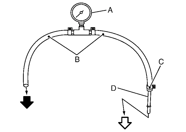

: To high pressure fuel pump 
: To quick connector CAUTION:
-
Use suitable fuel hose for fuel pressure check (genuine NISSAN fuel hose)
-
To avoid unnecessary force or tension to hose, use moderately long fuel hose for fuel pressure check.
-
Wipe off oil or dirt from hose insertion part using cloth moistened with gasoline.
-
Apply proper amount of gasoline on the hose insertion part.
-
Use NISSAN genuine hose clamp (part number: 16439 N4710 or 16439 N4710)
-
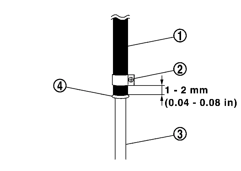
Install hose clamp to the hose end position within 1- 2 mm (0.04 - 0.08 in) and tighten hose clamp to the specified torque.
Tightening torque: 1 - 1.5 Nôñm (0.1 - 0.15 kgãm) -
-
Disconnect quick connector and disconnect fuel feed hose from high pressure fuel pump. Refer to Exploded View.
CAUTION:
-
Make sure to release fuel pressure before removal of fuel line.
-
Do the following procedure in the place where ventilation is good without the combustible.
 NOTE:
NOTE:
-
Prepare pans or saucers under the disconnected fuel line because the fuel may spill out. The fuel pressure cannot be completely released because this models do not have fuel return system.
-
Use fuel tube adapter (SST: KV10120000) and fuel pressure gauge to check fuel pressure.
-
-
Install fuel hose for fuel pressure check to high pressure fuel pump with hose clamp.
CAUTION:
-
Wipe off oil or dirt from hose insertion part using cloth moistened with gasoline.
-
Apply proper amount of gasoline on the hose insertion part.
-
Insert fuel hose for fuel pressure check
 until it touchesthe spool
  on high pressure fuel pump
  .
. -
Use NISSAN genuine hose clamp
 (part number: 16439ãN4710 or 16439ã40U00).
 -
Install hose clamp to the hose end position within 1- 2 mm (0.04 - 0.08 in) and tighten hose clamp to the specified torque.
Tightening torque: 1 - 1.5 Nôñm (0.1 - 0.15 kgãm) -
After connecting fuel hose for fuel pressure check, pull the hose with a force of approximately 100 N (approximately 10 kg, 22 lb) to confirm fuel sub tube does not come off.
-
-
Install fuel pressure check adapter to quick connector of fuel feed hose.
-
Turn ignition switch ON and check for fuel leakage.
-
Start engine and check for fuel leakage.
-
Stop the engine.
-
Turn ignition switch ON and read the indication of fuel pressure gauge.
At ignition switch ON : Approximately 450 kPa (4.5 bar, 4.59 kg/Ð , 65.25 psi)
Is the inspection result normal?
YES>>INSPECTION END
NO>>GO TO 2.
CHECK FUEL HOSE
Check fuel hose for clogging.
Is the inspection result normal?
YES>>Repair or replace the malfunctioning part.
NO>>Replace fuel filter and fuel pump assembly. Refer to Removal and Installation.
Other materials:
Front Camera Unit Heater
Component Inspection
CHECK FRONT CAMERA UNIT HEATER
Check the resistance between the front camera unit heater terminals.
Front camera unit heater Resistance [ãÎ]
Terminal
1
4
7 ã 20
Is the inspection result normal?
YES>>
INSPECTION END
NO>>
Replace the fro ...
Commande de feux de dûˋtresse
Appuyez sur cette commande pour signaler aux autres usagers que vous devez vous arrûˆter ou stationner en urgence. Tous les clignotants du Nissan Rogue fonctionnent alors simultanûˋment.
AVERTISSEMENT
En cas dãarrûˆt dãurgence, garez le vûˋhicule le plus loin possible de la circulatio ...
Fuel Pump Control Module
Component Inspection
CHECK FUEL PUMP CONTROL MODULE (FPCM)
Check the voltage between FPCM terminals under the following conditions.
FPCM Condition
Voltage
(Approx.)
Connector + ã
Terminal
B97
6
5
For 1 second after turning ignition switch ON
9.9 V
More than ...