Nissan Rogue (T33) 2021-Present Service Manual: Fuel Level Sensor Signal Circuit
Component Function Check
PERFORM COMPONENT FUNCTION CHECK (1)
-
Ignition switch OFF.
-
Disconnect fuel level sensor unit, fuel pump and FPCM (fuel level sensor) (main) harness connector.
-
Connect variable resistor between harness connector terminals located on the Nissan Ariya vehicle side of the fuel level sensor unit.
Fuel level sensor unit, fuel pump and FPCM (fuel level sensor) (main) Connector Terminals B97 1 2 -
Set variable resistor according to the resistance value shown in the following table and place ignition switch ON.
Resistance (Ω)*
(Approx.)Fuel gauge indication position
(Approx.)Less than 94.5 Full 140 3/4 186 1/2 232 1/4 255 1/8 More than 278 Empty *: Reference resistance values used when the combination meter judges the indication position of the fuel gauge.
Is the inspection result normal?
YES>>GO TO 2.
NO>>Refer to Diagnosis Procedure.
PERFORM COMPONENT FUNCTION CHECK (2)
Check the fuel level sensor unit, fuel pump and FPCM (fuel level sensor) (main). Refer to Component Inspection.
Is the inspection result normal?
YES>>Inspection End.
NO>>Replace the fuel level sensor unit, fuel filter and fuel pump assembly. Refer to Removal and Installation.
DiagnosisProcedure
CHECK FUEL LEVEL SENSOR UNIT, FUEL PUMP AND FPCM (FUEL LEVEL SENSOR) (MAIN) CIRCUIT
-
Ignition switch OFF.
-
Disconnect combination meter harness connector and fuel level sensor unit, fuel pump and FPCM (fuel level sensor) (main) harness connector.
-
Check continuity between combination meter harness connector and fuel level sensor unit, fuel pump and FPCM (fuel level sensor) (main) harness connector.
Combination meter Fuel level sensor unit, fuel pump and FPCM (fuel level sensor) (main) Continuity Connector Terminal Connector Terminal M73 (U.S.A. production)
M77 (Japan production)35 B97 2 Yes -
Check continuity between combination meter harness connector and ground.
Combination meter Ground Continuity Connector Terminal M73 (U.S.A. production)
M77 (Japan production)35 No
Is the inspection result normal?
YES>>GO TO 2.
NO>>Repair harness or connector.
CHECK FUEL LEVEL SENSOR UNIT, FUEL PUMP AND FPCM (FUEL LEVEL SENSOR) (MAIN) GROUND CIRCUIT
-
Check continuity between fuel level sensor unit, fuel pump and FPCM (fuel level sensor) (main) harness connector and combination meter harness connector.
Fuel level sensor unit, fuel pump and FPCM (fuel level sensor) (main) Combination meter Continuity Connector Terminal Connector Terminal B97 1 M73 (U.S.A. production)
M77 (Japan production)36 Yes -
Check continuity between fuel level sensor unit, fuel pump and FPCM (fuel level sensor) (main) harness connector and ground.
Fuel level sensor unit, fuel pump and FPCM (fuel level sensor) (main) Ground Continuity Connector Terminal B97 1 No
Is the inspection result normal?
YES>>Replace combination meter. Refer to Removal and Installation.
NO>>Repair harness or connector.
Component Inspection
2WD MODELS
CHECK FUEL LEVEL SENSOR UNIT, FUEL PUMP AND FPCM (FUEL LEVEL SENSOR) (MAIN)
-
Remove the fuel level sensor unit, fuel pump and FPCM (fuel level sensor) (main). Refer to Removal and Installation.
-
Check the resistance between fuel level sensor unit, fuel pump and FPCM (fuel level sensor) (main).
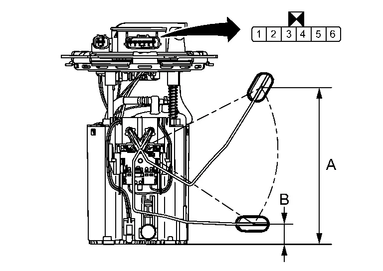
Terminals Condition Resistance (Ω)
(Approx.)Height [mm (in)] Fuel level sensor unit, fuel pump and FPCM (fuel level sensor) (main) 1 2 Full* (A) 91 174.6 (6.87) Empty* (B) 283 22.0 (0.87) *: When float rod is contact with stopper.
Is inspection result normal?
YES>>Inspection End.
NO>>Replace fuel level sensor unit, fuel pump and FPCM (fuel level sensor) (main). Refer to Removal and Installation.
AWD MODELS
CHECK FUEL LEVEL SENSOR UNIT, FUEL PUMP AND FPCM (FUEL LEVEL SENSOR) (MAIN)
-
Remove the fuel level sensor unit, fuel pump and FPCM (fuel level sensor) (main). Refer to Removal and Installation.
-
Check the resistance between fuel level sensor unit, fuel pump and FPCM (fuel level sensor) (main).
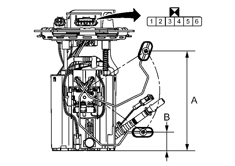
Terminals Condition Resistance (Ω)
(Approx.)Height [mm (in)] Fuel level sensor unit, fuel pump and FPCM (fuel level sensor) (main) 1 2 Full* (A) 28 164.8 (6.49) Empty* (B) 113.5 28.2 (1.11) *: When float rod is contact with stopper.
Is inspection result normal?
YES>>GO TO 2.
NO>>Replace fuel level sensor unit, fuel pump and FPCM (fuel level sensor) (main). Refer to Removal and Installation.
CHECK FUEL LEVEL SENSOR UNIT (SUB)
-
Remove the fuel level sensor unit (sub). Refer toRemoval and Installation .
-
Check the resistance between fuel level sensor unit (sub).
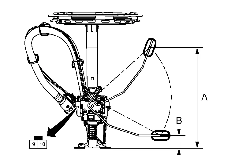
Terminals Condition Resistance (Ω)
(Approx.)Height [mm (in)] Fuel level sensor unit (sub) 9 10 Full* (A) 63 185.2 (7.29) Empty* (B) 169.5 19.9 (0.78) *: When float rod is contact with stopper.
Is inspection result normal?
YES>>Inspection End.
NO>>Replace fuel level sensor unit (sub). Refer to Removal and Installation.
Other materials:
Power Supply and Ground Circuit
Side Radar Front Lh
Diagnosis Procedure
CHECK FUSE
Check that the following fuse is not blown:
Signal name Fuse No.
Ignition power supply
9 (10 A)
Is the fuse blown?
YES>>
Replace the blown fuse after repairing the affected circuit.
NO>>
GO TO 2.
CHECK POWER SU ...
Component Parts
Engine Control System
Component Parts Location
ENGINE ROOM COMPARTMENT
Right front of Nissan Ariya vehicle
Left front of vehicle
Nissan Ariya Vehicle front
IPDM E/R
ECM
Admission valve
Turbocharger boost senso ...
Symptom Diagnosis. Wiper Deicer Does Not Operate
Diagnosis Procedure
CHECK WIPER DEICER RELAY
Check wiper deicer relay.
Refer to Component Inspection.
Is the inspection result normal?
YES>>
GO TO 2.
NO>>
Repair or replace the malfunctioning parts.
CHECK WIPER DEICER
Check wiper deicer.
Refer to Component Function Check.
I ...