Nissan Rogue (T33) 2021-Present Service Manual: Front Blower Motor
Diagnosis Procedure
CHECK FUSE
-
Ignition switch OFF.
-
Check that the following fusible link are not blown (open).
Unit Location Fuse No. Capacity Front blower motor Fuse block (J/B) LL 40 A
Is the fuses blown (open)?
YES>>Replace the blown (open) fusible link after repairing the affected circuit if a fusible link are blown (open).
NO>>GO TO 2.
CHECK FRONT BLOWER MOTOR POWER SUPPLY
-
Disconnect the front blower motor connector.
-
Ignition switch ON.
-
Check voltage between front blower motor harness connector and ground.
(+) (‚àí) Voltage Front blower motor Connector Terminal M144 2 Ground Battery voltage
Is the inspection result normal?
YES>>GO TO 4.
NO>>GO TO 3.
CHECK FRONT BLOWER MOTOR POWER SUPPLY CIRCUIT FOR OPEN
-
Ignition switch OFF.
-
Disconnect fuse block (J/B) harness connector.
-
Check continuity between fuse block (J/B) harness connector and front blower motor harness connector.
Fuse block (J/B) Front blower motor Continuity Connector Terminal Connector Terminal M33 1A M144 2 Yes
Is the inspection result normal?
YES>>Repair the front blower motor power supply circuit.
NO>>Repair the harnesses or connectors.
CHECK FRONT BLOWER MOTOR GROUND CIRCUIT FOR OPEN
-
Ignition switch OFF.
-
Check continuity between front blower motor harness connector and ground.
Front blower motor (–) Continuity Connector Terminal M144 4 Ground Yes
Is the inspection result normal?
YES>>GO TO 5.
NO>>Repair the harnesses or connectors.
CHECK FRONT BLOWER MOTOR CONTROL SIGNAL
-
Connect front blower motor connector.
-
Ignition switch ON.
-
Check duty ratios between front blower motor harness connector and ground by using an oscilloscope.
(+) (‚àí) Condition Output waveform Front blower motor Connector Terminal M144 1 Ground Front blower motor: OFF Battery voltage Front blower motor: 1st speed (manual) 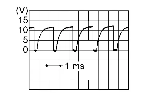
Front blower motor: 11th speed (manual) 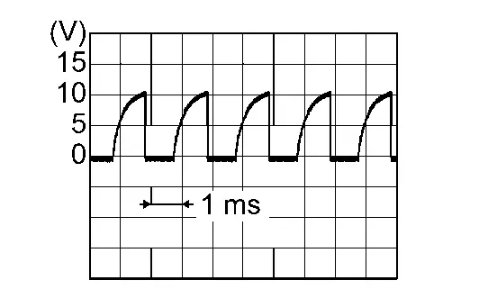
Is the inspection result normal?
YES>>Replace front blower motor. Refer to Removal and Installation.
NO>>GO TO 6.
CHECK FRONT BLOWER MOTOR CONTROL SIGNAL CIRCUIT FOR OPEN
-
Ignition switch OFF.
-
Disconnect front blower motor connector and A/C amp. connector.
-
Check continuity between front blower motor harness connector and A/C amp. harness connector.
Front blower motor A/C amp. Continuity Connector Terminal Connector Terminal M144 1 M54 34 Yes
Is the inspection result normal?
YES>>GO TO 7.
NO>>Repair the harnesses or connectors.
REPLACE FRONT BLOWER MOTOR
-
Replace front blower motor. Refer to Removal and Installation.
-
Ignition switch ON.
-
Change fan speed from 1st – 11th, and check that front blower motor operates normally.
Is the inspection result normal?
YES>>Inspection End.
NO>>Replace the A/C amp. Refer to Removal and Installation.
Component Inspection (Front Blower Motor)
CHECK FRONT BLOWER MOTOR-I
-
Remove front blower motor. Refer to Removal and Installation.
-
Check that there is not any mixing foreign object in the front blower motor.
Is the inspection result normal?
YES>>GO TO 2.
NO>>Replace front blower motor. Refer to Removal and Installation.
CHECK FRONT BLOWER MOTOR-II
Check that there is not breakage or damage in the front blower motor.
Is the inspection result normal?
YES>>GO TO 3.
NO>>Replace front blower motor. Refer to Removal and Installation.
CHECK FRONT BLOWER MOTOR-III
Check that front blower motor turns smoothly.
Is the inspection result normal?
YES>>Inspection End.
NO>>Replace front blower motor. Refer to Removal and Installation.
Other materials:
Meter/m&a (combination Meter)
B2202-11 Fuel Sender
DTC Description
DTC DETECTION LOGIC DTC No.
CONSULT screen terms
(Trouble diagnosis content) DTC detected condition
B2202-11
Fuel level sensor
(Fuel level sensor)
Diagnosis condition
When ignition switch is ON.
Signal (terminal)
Fuel level sensor si ...
Steering Switch Signal B Circuit
Component Function Check
CHECK COMBINATION METER INPUT SIGNAL
CONSULT
Ignition switch ON.
Select “Steering switch input” in “Data monitor” mode of “M&A”.
Check that the function operates normally according to the following conditions:
Condition Value
CONTRO ...
Nissanconnect. Preparation. Preparation
Preparation
Commercial Service Tools
Tool Description
Power tool
Loosening screws
Always Replace With New Parts
Always Replace With New PartsNever Reuse These PartsPart CodeFor additional information:
Washer
-
ROOF ANTENNA EXPLODED VIEW
...