Nissan Rogue (T33) 2021-Present Service Manual: Door Motor
Diagnosis Procedure
 NOTE:
NOTE:
If all of door motor DTCs are detected, check this circuit.
CHECK DOOR MOTOR POWER SUPPLY
-
Ignition switch ON.
-
Check voltage between intake door motor harness connector and A/C amp. harness connector.
| (+) | (ŌłÆ) | Voltage | ||
|---|---|---|---|---|
| Intake door motor | A/C amp. | |||
| Connector | Terminal | Connector | Terminal | |
| M147 | 1 | M55 | 58 | Battery voltage |
Is the inspection result normal?
YES>>GO TO 2.
NO>>GO TO 6.
CHECK DOOR MOTOR GROUND CIRCUIT FOR OPEN
-
Ignition switch OFF.
-
Disconnect intake door motor connector and A/C amp. connector.
-
Check continuity between intake door motor harness connector and A/C amp. harness connector.
Intake door motor A/C amp. Continuity Connector Terminal Connector Terminal M147 2 M54 27 Yes
Is the inspection result normal?
YES>>GO TO 3.
NO>>Repair harness or connector.
CHECK DOOR MOTOR LIN SIGNAL
-
Connect intake door motor connector and A/C amp. connector.
-
Ignition switch ON.
-
Confirm output waveform between intake door motor harness connector and A/C amp. harness connector with oscilloscope.
(+) (ŌłÆ) Output waveform Intake door motor A/C amp. Connector Terminal Connector Terminal M147 3 M55 58 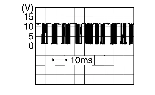
Is the inspection result normal?
YES>>Inspection End.
NO>>GO TO 4.
CHECK DOOR MOTOR LIN SIGNAL CIRCUIT FOR OPEN
-
Ignition switch OFF.
-
Disconnect A/C amp. and intake door motor connector.
-
Check continuity between intake door motor harness connector and A/C amp. harness connector.
Intake door motor A/C amp. Continuity Connector Terminal Connector Terminal M147 1 M54 1 Yes
Is the inspection result normal?
YES>>GO TO 5.
NO>>Repair harness or connector.
CHECK DOOR MOTOR LIN SIGNAL CIRCUIT FOR SHORT
-
Ignition switch OFF.
-
Disconnect following connectors.
-
Air mix door motor
-
Mode door motor
-
-
Check continuity between A/C amp. harness connector and ground.
A/C amp. (ŌĆō) Continuity Connector Terminal M54 2 Ground No
Is the inspection result normal?
YES>>Replace A/C amp. Refer to Removal and Installation.
NO>>Repair harness or connector.
CHECK DOOR MOTOR POWER SUPPLY CIRCUIT FOR OPEN
-
Ignition switch OFF.
-
Disconnect intake door motor and A/C amp. connector.
-
Check continuity between intake door motor harness connector and A/C amp. harness connector.
Intake door motor A/C amp. Continuity Connector Terminal Connector Terminal M147 1 M54 1 Yes
Is the inspection result normal?
YES>>GO TO 7.
NO>>Repair harness or connector.
CHECK DOOR MOTOR POWER SUPPLY CIRCUIT FOR SHORT
-
Disconnect following connectors.
-
Air mix door motor
-
Mode door motor
-
-
Check continuity between A/C amp. harness connector and ground.
A/C amp. (ŌĆō) Continuity Connector Terminal M54 1 Ground No
Is the inspection result normal?
YES>>Replace A/C amp. Refer to Removal and Installation.
NO>>Repair harness or connector.
Other materials:
Transfer: Ty92a. Periodic Maintenance. Transfer Oil
Transfer Oil
Inspection
OIL LEAKAGE
Remove engine under cover during working. Refer to Exploded View.
Check transfer surrounding area (oil seal, drain plug, and filler plug etc.) for oil leakage.OIL LEVEL
Remove engine under cover during working. Refer to Exploded View.
Check oil level ...
Symptom Diagnosis. Low Tire Pressure Warning Lamp Blinks
Description
When the ignition switch is placed ON, the low tire pressure warning
lamp blinks. And then 1 minute later, low tire pressure warning lamp
turns ON.
Diagnosis Procedure
CHECK TIRE PRESSURE SENSOR INSTALLATION
Check visually that tire pressure sensors are installed to each wheels c ...
Symptom Diagnosis. Interior Lighting System Symptoms
Symptom Table
NOTE:
Perform self diagnosis result with CONSULT before the symptom diagnosis. Perform the trouble diagnosis if any DTC is detected.
Symptom Possible cause Inspection item
All the following lamps do not turn ON:
Map lamp assembly
Room lamp
Personal lamp
Lu ...