
Nissan Rogue (T33) 2021-Present Service Manual: Engine Stand Setting
Setting
 NOTE:
NOTE:
Explained here is how to disassemble with engine stand supporting transaxle surface. When using different type of engine stand, note with difference in steps and etc.
Remove the engine and the transaxle assembly from the vehicle, and separate the transaxle from the engine. Refer to Removal and Installation.
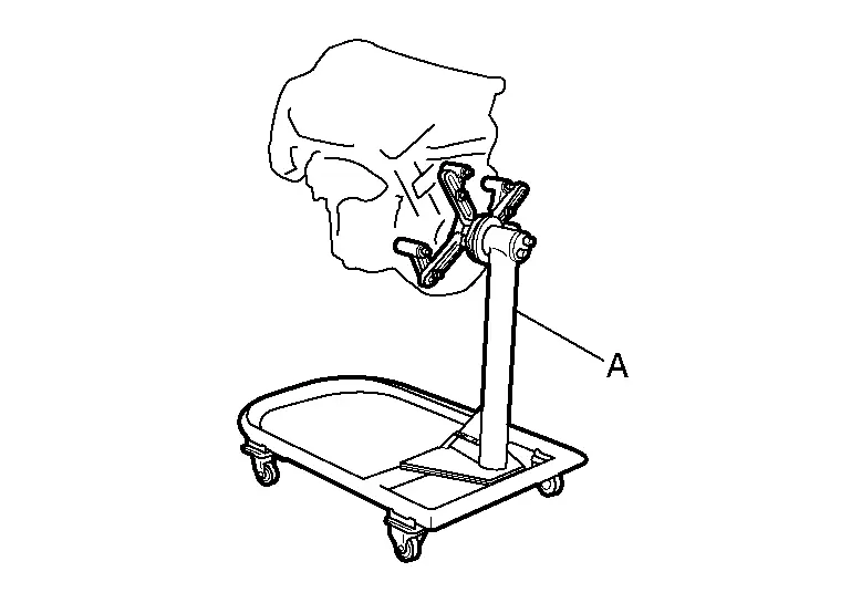
Install engine to engine stand with the following procedure:Remove drive plate. Refer to Removal and Installation. Lift the engine with a hoist to install it onto widely use engine stand.
CAUTION:
Use the engine stand that has a load capacity [approximately 135 kg (298 lb) or more] large enough for supporting the engine weight.
NOTE:
The figure shows an example of widely used engine stand (A) that can support mating surface of transaxle with drive plate removed.
CAUTION:
Before removing the hanging chains, check the engine stand is stable and there is no risk of overturning.
Drain engine oil. Refer to Draining.
CAUTION:
Be sure to clean drain plug and install with new drain plug washer.
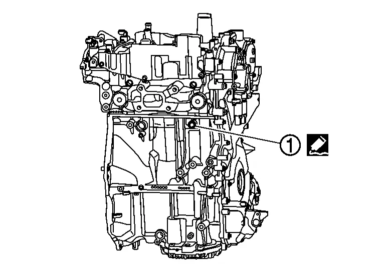
Drain engine coolant by removing water drain plug  from inside of the engine.
Use Genuine RTV Silicone Sealant or an equivalent.Refer to Recommended Chemical Products and Sealants.
| Tightening torque | :Refer to Disassembly & Assembly. |
Other materials:
Fuel Injector and Fuel Tube
Exploded View
Fuel rail pressure sensor
High pressure fuel rail insulator
High pressure fuel rail
O-ring (black)
Support disc
Fuel injector
Decoupling element
Valve seat
Retaining ring spring
Holding down appliance
Stud bolt
...
Precaution. Tow Truck Towing
Tow Truck Towing
WARNING:
Never ride in a vehicle that is being towed.
Never get under your Nissan Ariya vehicle after it has been lifted by a tow truck.
CAUTION:
All applicable state or Provincial (in Canada) laws and local laws regarding the towing operation must be obeyed.
...
C1f00-1c Control Unit
DTC Description
DTC DETECTION LOGIC DTC
CONSULT screen terms
(Trouble diagnosis content) DTC detection condition
C1F00
1C
CONTROL UNIT
(Control unit)
Diagnosis condition
When engine is running
Signal (terminal)
—
Threshold
ADAS control unit 2 internal malfunct ...