Nissan Rogue (T33) 2021-Present Service Manual: Ecu Diagnosis Information :: Automatic Back Door Control Unit
Reference Value
VALUES ON THE DIAGNOSIS TOOL
 NOTE:
NOTE:
The following table includes information (items) inapplicable to this Nissan Ariya vehicle. For information (items) applicable to this vehicle, refer to CONSULT display items.
| Monitor Item | Condition | Value/Status | |
|---|---|---|---|
| Automatic back door status | Automatic back door system | Malfunction: All functions cannot operate | NG 1 |
| Malfunction: Only AUTO CLOSER FUNCTION can operate | NG 2 | ||
|
This item is displayed, but cannot be monitored |
Not used | ||
| Normal | Normal | ||
| Automatic back door position learn status | Calibration of automatic back door position information | Not complete | Yet |
| Complete | Done | ||
| Automatic back door close switch | Automatic back door close switch | Released | Off |
| Pressed | On | ||
| Automatic back door switch | Automatic back door switch | Released | Off |
| Short pressed | Short | ||
| Long pressed | Long | ||
|
This item is displayed, but cannot be monitored |
Not used | ||
| Lock & close switch | Automatic back door lock and close switch | Released | Off |
| Pressed | On | ||
| Keyless signal (back door) | Intelligent Key button (back door) | Released | Off |
| Short pressed | Short | ||
| Long pressed | Long | ||
|
This item is displayed, but cannot be monitored |
Not used | ||
| Automatic back door operation request (opener switch) | Back door opener switch |
This item is displayed, but cannot be monitored |
Not used |
| Released | Off | ||
| Pressed | On | ||
|
This item is displayed, but cannot be monitored |
Not used | ||
| Automatic back door operation request (hands free) | Hands free sensor | Other than bellow | Off |
| Detected | On | ||
| Spindle sensor LH | Back door | Open | The numeral value increases |
| Close | The numeral value decreases | ||
| Spindle sensor RH | Back door | Open | The numeral value increases |
| Close | The numeral value decreases | ||
| Half latch switch | Back door | Fully closed/ half latch | Off |
| Open | On | ||
| Close switch | Back door | Other than bellow | Off |
| Closure operation (open) | On | ||
| Open switch | Back door | Other than bellow | Off |
| Closure operation (close) | On | ||
| Touch sensor LH | Touch sensor LH | Other than bellow | Off |
| Detect obstruction | On | ||
| Circuit open | Open | ||
|
This item is displayed, but cannot be monitored |
Not used | ||
| Touch sensor RH | Touch sensor RH | Other than bellow | Off |
| Detect obstruction | On | ||
| Circuit open | Open | ||
|
This item is displayed, but cannot be monitored |
Not used | ||
| Nissan Ariya Vehicle condition | Vehicle status | Sleep status | Sleep |
|
This item is displayed, but cannot be monitored |
Not used | ||
|
AUTO ACC status (remaining time 60 seconds or less) IGN OFF ‚áí Door open IGN OFF ‚áí Door open |
ACC 1 | ||
|
AUTO ACC status (remaining time 60 seconds or more) IGN ON ‚áí IGN OFF |
ACC 2 | ||
|
This item is displayed, but cannot be monitored |
Not used | ||
| Ignition switch ON | IGN ON | ||
| Engine cranking | Cranking | ||
| Engine running | Running | ||
| Engine restart | Restart | ||
| stop/start operation | stop/start | ||
|
This item is displayed, but cannot be monitored |
Unavailable | ||
| Door lock operation | Other than bellow | Off | |
| When door lock operation using door request switch or Intelligent Key | On | ||
| Nissan Ariya Vehicle speed | While driving | Equivalent to speedometer reading | |
| Parking brake switch | Parking brake | Off | Off |
| On | On | ||
| P range | Selector lever | Other than P position | Off |
| P position | On | ||
| Transmission type | Transmission type is displayed | AT/CVT | |
| Ignition switch | Ignition switch | Other than ON position | Off |
| ON position | On | ||
| Automatic back door control unit power supply | — | Battery voltage | |
| Sleep/wake up | Nissan Ariya Vehicle status | Sleep status | Sleep |
|
This item is displayed, but cannot be monitored |
Not used | ||
|
This item is displayed, but cannot be monitored |
Not used | ||
| Wake–up status | Wake up | ||
| Door lock interlock operation condition | Automatic back door system (automatic back door lock and close switch operation) | Other than bellow | Off |
| Any door open | NG 1 | ||
| Intelligent Key cannot detected or Key ID unmatched | NG 2 | ||
| Normal | Normal | ||
| Meter setting 1 (automatic back door) | Power back door setting | Other than bellow | Not ope |
| OFF | Off | ||
| ON | On | ||
| Reset | Reset | ||
| Sleep condition |
This item is displayed, but cannot be monitored |
Not used | |
| Automatic back door system is operate | NG | ||
| Automatic back door system is not operate | OK | ||
|
This item is displayed, but cannot be monitored |
Not used | ||
| Meter setting 2 (automatic back door) | Power back door setting | OFF | Off |
| ON | On | ||
| Automatic back door operation status | Automatic back door | Other than bellow | Off |
| Open operation | Open | ||
| Close operation | Close | ||
| Lock and close oeration | Doorlock | ||
| Automatic back door operation permission | Automatic back door system operating condition | Operation not permitted | NG |
| Activation permission | OK | ||
| When low battery voltage | Stop | ||
|
This item is displayed, but cannot be monitored |
Not used | ||
| Nissan Ariya Vehicle speed diagnosis 1 | When the received vehicle speed signal is normal | OK | |
| When the received Nissan Ariya vehicle speed signal is abnormal | NG | ||
| Vehicle speed diagnosis 2 | When the received Nissan Ariya vehicle speed signal is normal | OK | |
| When the received Nissan Ariya vehicle speed signal is abnormal | NG | ||
| Open switch error count | Displays the number of count up of the open switch malfunction. | 0 – 3 | |
| Close switch error count | Displays the number of count up of the close switch malfunction. | 0 – 3 | |
TERMINAL LAYOUT
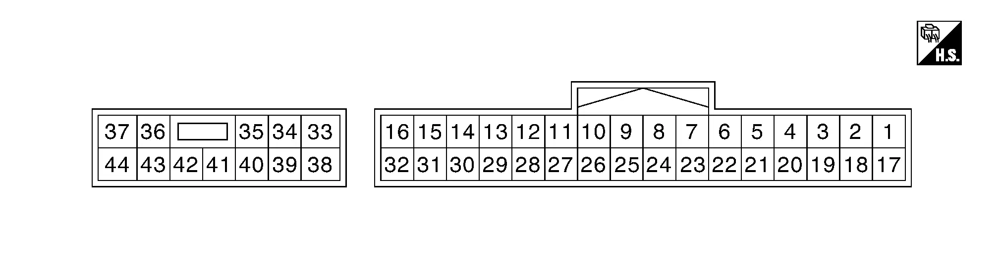
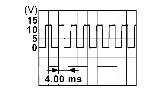
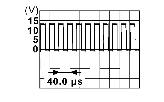
PHYSICAL VALUES
NOTE:
Waveform reference
|
Terminal No. (Wire color) | Description | Condition |
Voltage (Approx.) | |||
|---|---|---|---|---|---|---|
| (+) | (–) | Signal name | Input/Output | |||
|
3 (W) |
Ground | Automatic back door close switch | Input | Automatic back door close switch | Pressed | 0 V |
| Released | Battery voltage | |||||
|
4 (LG) |
Ground | Automatic back door switch | Input | Automatic back door switch | Pressed | 0 V |
| Released | Battery voltage | |||||
|
9 (BR) |
Ground | Close switch signal | Input | Back door closure motor | Open operation | 0 V |
| Other than above | Battery voltage | |||||
|
10 (SB) |
Ground | Half latch switch signal | Input | Back door | Open | 0 V |
| Fully closed/half latch | Battery voltage | |||||
|
11 (V) |
Ground | Open switch signal | Input | Back door closure motor | Close operation | 0 V |
| Other than above | Battery voltage | |||||
|
12 (G) |
Ground | Touch sensor LH signal | Input | Touch sensor LH | Detect obstruction | 0.2 - 3 V |
| Other than above | 3.4 - 6.5 V | |||||
|
13 (L) |
Ground | Touch sensor RH signal | Input | Touch sensor RH | Detect obstruction | 0.2 - 3 V |
| Other than above | 3.4 - 6.5 V | |||||
|
14 (GR) |
Ground | Touch sensor ground | Input | — | 0 V | |
|
16 (LA/R) |
Ground | CAN-Low | Input/Output | — | — | |
|
18 (LA/SB) |
Ground | Encoder RH B signal | Input | — | 0 V | |
|
19 (LA/LG) |
Ground | Encoder RH A signal | Input | — | 0 V | |
|
20 (LA/P) |
Ground | Encoder RH power supply | Output | — | 0 V | |
|
21 (P) |
Ground | Automatic back door lock and close switch | Input | Automatic back door lock and close switch | Pressed | 0 V |
| Released | Battery voltage | |||||
|
28 (LA/Y) |
Ground | Encoder ground | — | — | 0 V | |
|
29 (LA/G) |
Ground | Encoder LH B signal | Input | Back door | Moving (auto) |
|
| When stopped | 0 V or Battery voltage | |||||
|
30 (LA/BR) |
Ground | Encoder LH A signal | Input | Back door | Moving (auto) |
|
| When stopped | 0 V or Battery voltage | |||||
|
31 (LA/V) |
Ground | Encoder LH power supply | Output | — | Battery voltage | |
|
32 (LA/L) |
Ground | CAN-High | Input/Output | — | — | |
|
33 (LA/L) |
Ground | Back door closure motor (open) | Output | Back door | Open operation | Battery voltage |
| Other than above | 5 V | |||||
|
34 (LA/SB) |
Ground | Back door closure motor (close) | Output | Back door | Close operation | Battery voltage |
| Other than above | 5 V | |||||
|
35 (BR) |
Ground | Spindle motor RH (open) | Output | Back door | Auto open operation |
|
| Auto close operation | 0 V | |||||
|
37 (BR) |
Ground | Power supply (BAT) | Input | — | Battery power supply | |
|
38 (BR) |
Ground | Spindle motor LH (open) (USA production) | Output | Back door | Auto open operation |
|
| Auto close operation | 0 V | |||||
|
38 (B) |
Ground | Spindle motor LH (open) (Japan production) | Output | Back door | Auto open operation |
|
| Auto close operation | 0 V | |||||
|
39 (W) |
Ground | Spindle motor LH (close) | Output | Back door | Auto close operation |
|
| Auto open operation | 0 V | |||||
|
40 (G) |
Ground | Spindle motor RH (close) | Output | Back door | Auto close operation |
|
| Auto open operation | 0 V | |||||
|
42 (B) |
Ground | Ground | — | — | 0 V | |
|
44 (LA/B) |
Ground | Ground (noise shield) | — | — | 0 V | |
Fail-safe
Refer to Fail-safe.
DTC Inspection Priority Chart
If some DTCs are displayed at the same time, perform inspections one by one based on the following priority chart.
| Priority | DTC |
|---|---|
| 1 |
|
| 2 |
|
DTC Index
NOTE:
Details of time display
-
1 - 39: Displayed if any previous malfunction is present when current condition is normal. It increases like 1 ‚Üí 2 ‚Üí 3...38 ‚Üí 39 after returning to the normal condition whenever ignition switch OFF ‚Üí ON. The counter remains at 39 even if the number of cycles exceeds it. It is counted from 1 again when turning ignition switch OFF ‚Üí ON after returning to the normal condition if the malfunction is detected again.
| CONSULT display | Fail-safe | Reference page |
|---|---|---|
| B2409-12: Half latch switch | √ó | DTC Description |
| B2409-14: Half latch switch | √ó | DTC Description |
| B2416-15: Touch sensor circuit RH open | √ó | DTC Description |
| B2417-15: Touch sensor circuit LH open | √ó | DTC Description |
| B2419-12: Open switch | √ó | DTC Description |
| B2419-14: Open switch | √ó | DTC Description |
| B2420-12: Close switch | √ó | DTC Description |
| B2420-14: Close switch | √ó | DTC Description |
| B2422-78: Back door position abnormal | √ó | DTC Description |
| B2422-79: Back door position abnormal | √ó | DTC Description |
| B2426-11: Spindle sensor LH | √ó | DTC Description |
| B2426-12: Spindle sensor LH | √ó | DTC Description |
| B2426-13: Spindle sensor LH | √ó | DTC Description |
| B2426-25: Spindle sensor LH | √ó | DTC Description |
| B2428-44: Automatic back door control unit | √ó | DTC Description |
| B2428-45: Automatic back door control unit | √ó | DTC Description |
| B2428-46: Automatic back door control unit | √ó | DTC Description |
| B2428-49: Automatic back door control unit | √ó | DTC Description |
| B2428-52: Automatic back door control unit | √ó | DTC Description |
| B2428-54: Automatic back door control unit | √ó | DTC Description |
| B242A-11: Closure motor | √ó | DTC Description |
| B242A-12: Closure motor | √ó | DTC Description |
| B242A-13: Closure motor | √ó | DTC Description |
| B242A-19: Closure motor | √ó | DTC Description |
| B242A-98: Closure motor | √ó | DTC Description |
| B2436-11: Spindle motor LH | √ó | DTC Description |
| B2436-12: Spindle motor LH | √ó | DTC Description |
| B2436-13: Spindle motor LH | √ó | DTC Description |
| B2436-19: Spindle motor LH | √ó | DTC Description |
| B2436-98: Spindle motor LH | √ó | DTC Description |
| B2437-11: Spindle motor RH | √ó | DTC Description |
| B2437-12: Spindle motor RH | √ó | DTC Description |
| B2437-13: Spindle motor RH | √ó | DTC Description |
| B2437-19: Spindle motor RH | √ó | DTC Description |
| B2437-98: Spindle motor RH | √ó | DTC Description |
| CONSULT display | Fail-safe | Reference page |
|---|---|---|
| U0075–00: Control module comm Bus C Off | × | DTC Description |
| U2141–87: CAN comm err (TCM) | × | DTC Description |
| U2148–87: CAN comm err (brake control unit) | × | DTC Description |
| U214E–87: CAN comm err (combination meter) | × | DTC Description |
| U214F–87: CAN comm err (BCM) | × | DTC Description |
| U215B–87: CAN comm err (IPDM E/R) | × | DTC Description |
Other materials:
Ecu Diagnosis Information. Ecm, Bcm, Intelligent Key Unit, Ipdm E/r
List of ECU Reference
ECU Reference
ECM
Values On The Diagnosis Tool
Values On The Diagnosis Tool
Physical Values
Physical Values
Fail-safe
Fail-safe
DTC Inspection Priority Chart
DTC Inspection Priority Chart
DTC Index
DTC Index
BCM
Reference Valu ...
Precaution. Precautions
Precaution for Supplemental Restraint System (SRS) "AIR BAG" and "SEAT BELT PRE-TENSIONER"
The Supplemental Restraint System such as “AIR BAG” and “SEAT BELT
PRE-TENSIONER”, used along with a front seat belt, helps to reduce the
risk or severity of injury to the driver and front passeng ...
Transaxle Assembly
Exploded View
O-ring
Tube A
Control valve
O-ring
Oil strainer
Oil pan gasket
Oil pan
Drain plug gasket
Drain plug
Magnet
O-ring
O-ring
Tube B
Lip seal
Transaxle assembly
: Always replace after every disassembly ...