Nissan Rogue (T33) 2021-Present Service Manual: Dtc/circuit Diagnosis :: Interior Room Lamp Power Supply Circuit
Diagnosis Procedure
Provides the interior room lamp power supply. Also cuts the power supply when the interior room lamp battery saver is activating.
CHECK INTERIOR ROOM LAMP POWER SUPPLY FUSE
-
Ignition switch OFF.
-
Check that the following fuse is not blown (open):
Signal name Location Fuse No. Capacity Ignition power supply Fuse block (J/B) 24 10 A
Is the fuse blown (open)?
YES>>Replace the blown (open) fuse after repairing the affected circuit if a fuse is blown (open).
NO>>GO TO 2.
CHECK INTERIOR ROOM LAMP POWER SUPPLY OUTPUT
 CONSULT
-
Ignition switch OFF.
-
Disconnect interior room lamp relay connector.
-
Ignition switch ON.
-
Select “Interior lamp” in “Active test” mode of “BCM”.
-
With operating the test item, check continuity between BCM harness connector and ground.
With type A meter (+) (–) Test item Continuity BCM Connector Terminal M51 29 Ground Interior lamp ON Yes OFF No With type B meter (+) (–) Test item Continuity BCM Connector Terminal M18 37 Ground Interior lamp ON Yes OFF No
Is the inspection result normal?
YES>>GO TO 4.
NO>>Continuity exists and remains unchanged: GO TO 3.
NO>>Continuity does not exist and remains unchanged: Replace BCM. Refer to Removal and Installation.
CHECK INTERIOR ROOM LAMP RELAY SIGNAL SHORT CIRCUIT
-
Ignition switch OFF.
-
Disconnect BCM connector.
-
Check continuity between BCM harness connector and ground.
With type A meter BCM — Continuity Connector Terminal M51 29 Ground No With type B meter BCM — Continuity Connector Terminal M18 37 Ground No
Is the inspection result normal?
YES>>Replace BCM. Refer to Removal and Installation.
NO>>Repair or replace harnesses.
CHECK INTERIOR ROOM LAMP RELAY SIGNAL OPEN CIRCUIT
-
Ignition switch OFF.
-
Disconnect BCM connector.
-
Check continuity between BCM harness connector and interior room lamp relay harness connector.
With type A meter BCM Interior room lamp relay Continuity Connector Terminal Connector Terminal M51 29 J-2 1 Yes With type B meter BCM Interior room lamp relay Continuity Connector Terminal Connector Terminal M18 37 J-2 1 Yes
Is the inspection result normal?
YES>>GO TO 5.
NO>>Repair or replace harnesses.
CHECK INTERIOR ROOM LAMP RELAY POWER SUPPLY CIRCUIT
Check voltage between interior room lamp relay harness connector and ground.
| (+) | (–) |
Voltage (Approx.) | |
|---|---|---|---|
| Interior room lamp relay | |||
| Connector | Terminal | ||
| J-2 | 2 | Ground | Battery voltage |
| 3 | |||
Is the inspection result normal?
YES>>GO TO 6.
NO>>Repair or replace harnesses.
CHECK INTERIOR ROOM LAMP RELAY
Check the interior room lamp relay. Refer to Component Inspection.
Is the inspection result normal?
YES>>GO TO 7.
NO>>Replace interior room lamp relay.
CHECK INTERIOR ROOM LAMP RELAY POWER SUPPLY OUTPUT
-
Disconnect the following connectors:
-
Map lamp assembly
-
Room lamp
-
Personal lamp LH
-
Personal lamp RH
-
Luggage room lamp
-
Sun visor LH (vanity mirror lamp switch)
-
Sun visor RH (vanity mirror lamp switch)
-
Mood lamp (front door LH)
-
Mood lamp (front door RH)
-
Mood lamp (center console tray LH)
-
Mood lamp (center console tray RH)
-
Mood lamp (center console)
-
-
Check continuity between interior room lamp relay harness connector and each interior room lamp harness connector.
Interior room lamp relay Each interior room lamp Continuity Connector Terminal Connector Terminal J-2 5 Map lamp assembly R6 1 Yes Room lamp R15 4 Luggage room lamp R23 2 Personal lamp LH R27 6 Personal lamp RH R28 6 Sun visor LH (vanity mirror lamp switch) R29 4 Sun visor RH (vanity mirror lamp switch) R30 4 Mood lamp (front door LH) D17 2 Mood lamp (front door RH) D109 2 Mood lamp (center console tray LH) M212 1 Mood lamp (center console tray RH) M211 1 Mood lamp (center console) M117 (with ambient LED lighting) 1 M116 (with ambient lighting)
Is the inspection result normal?
YES>>GO TO 8.
NO>>Repair or replace harnesses.
CHECK INTERIOR ROOM LAMP RELAY POWER SUPPLY OUTPUT SHORT CIRCUIT
Check continuity between interior room lamp relay harness connector and ground.
| Interior room lamp relay | — | Continuity | |
|---|---|---|---|
| Connector | Terminal | ||
| J-2 | 5 | Ground | No |
Is the inspection result normal?
YES>>Refer to Intermittent Incident.
NO>>Repair or replace harnesses.
Component Inspection
CHECK INTERIOR ROOM LAMP RELAY
-
Ignition switch OFF.
-
Disconnect interior room lamp relay connector.
-
Check continuity between interior room lamp relay terminals.
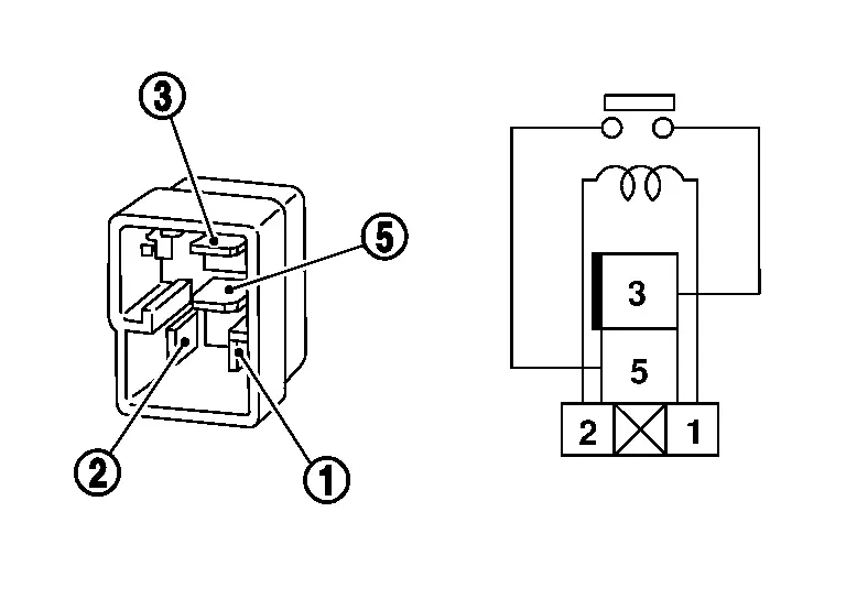
Interior room lamp relay Condition Continuity Terminal 

12 V direct current supply between terminals  and
and  .
. Yes No current supply No
Is the inspection result normal?
YES>>Inspection End.
NO>>Replace interior room lamp relay.
Other materials:
Removal and Installation. Driver Seat Control Unit
Removal and Installation
REMOVALRemove driver seat. Refer to Removal and Installation.
Disconnect driver seat control unit connector.
Remove fixing screws , and then remove driver seat control unit .
INSTALLATIONInstall in the reverse order of removal.CAUTION:
Be sure to perform ADDITIONAL SE ...
P0500 Vss
DTC Description
DESCRIPTIONECM receives vehicle speed signals from two
different paths via CAN communication line: One is from the ABS actuator
and electric unit (control unit) via the combination unit and the other
is from TCM.DTC DETECTION LOGIC DTC
CONSULT screen terms
(Trouble diagno ...
U214e Can Comm Circuit
DTC Description
DTC DETECTION LOGIC DTC
CONSULT screen terms
(Trouble diagnosis content)
DTC detection condition
U214E
87
CAN comm err (combination meter)
[CAN comm err (combination meter)]
Diagnosis condition
Ignition switch ON
Signal (terminal)
CAN communication ...