Nissan Rogue (T33) 2021-Present Service Manual: Control Valve
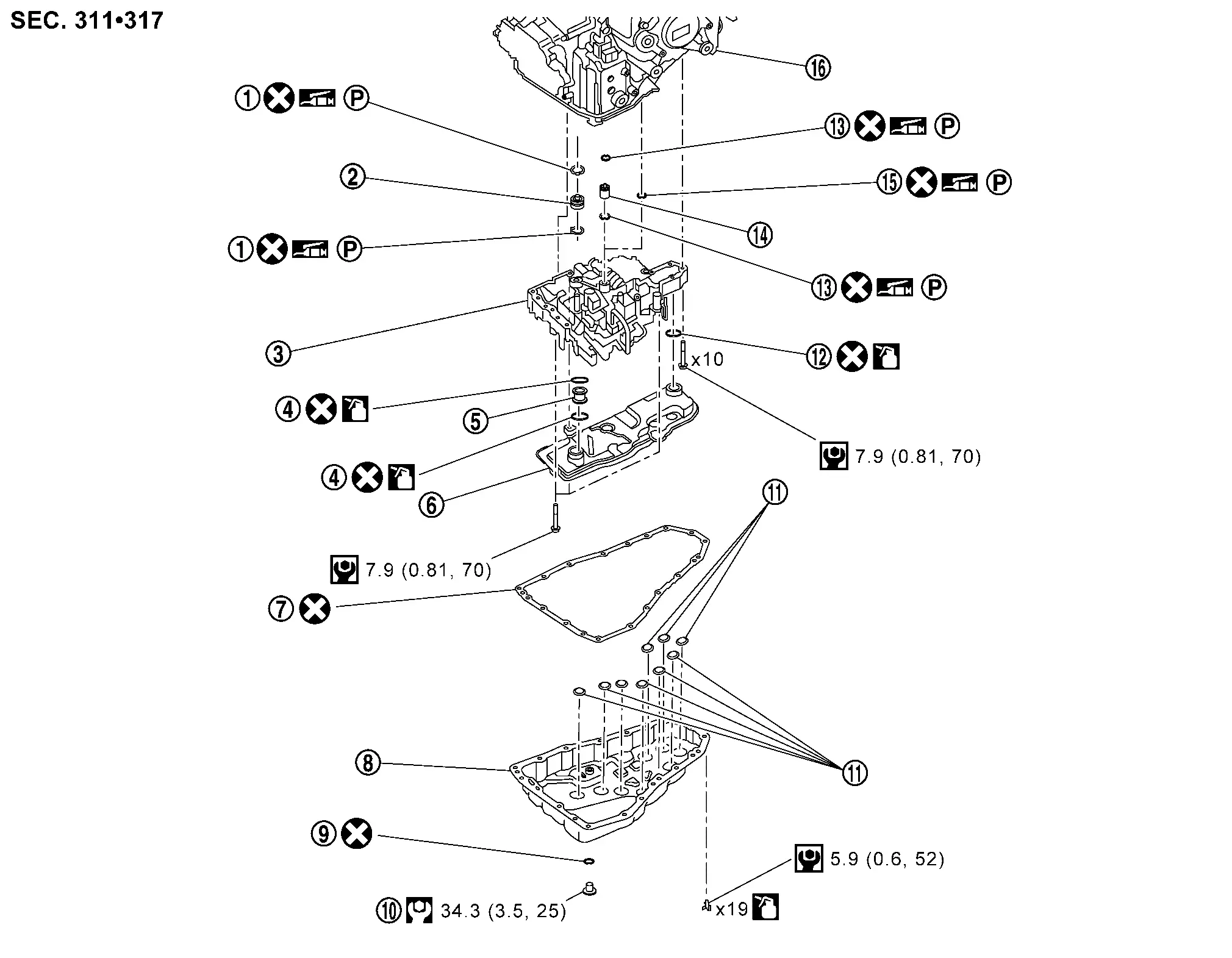
Exploded View
 |
O-ring |  |
Tube A |  |
Control valve |
 |
O-ring |  |
One-way valve |  |
Oil strainer |
 |
Oil pan gasket |  |
Oil pan |  |
Drain plug gasket |
 |
Drain plug |  |
Magnet |  |
O-ring |
 |
O-ring |  |
Tube B |  |
Lip seal |
 |
Transaxle assembly |
 : N·m (kg-m, in-lb)
 : N·m (kg-m, ft-lb)
 : Always replace after every disassembly.
 : Apply CVT fluid.
 : Apply petroleum jelly.
Removal and Installation
CAUTION:
Perform the following items when replacing the control valve.
-
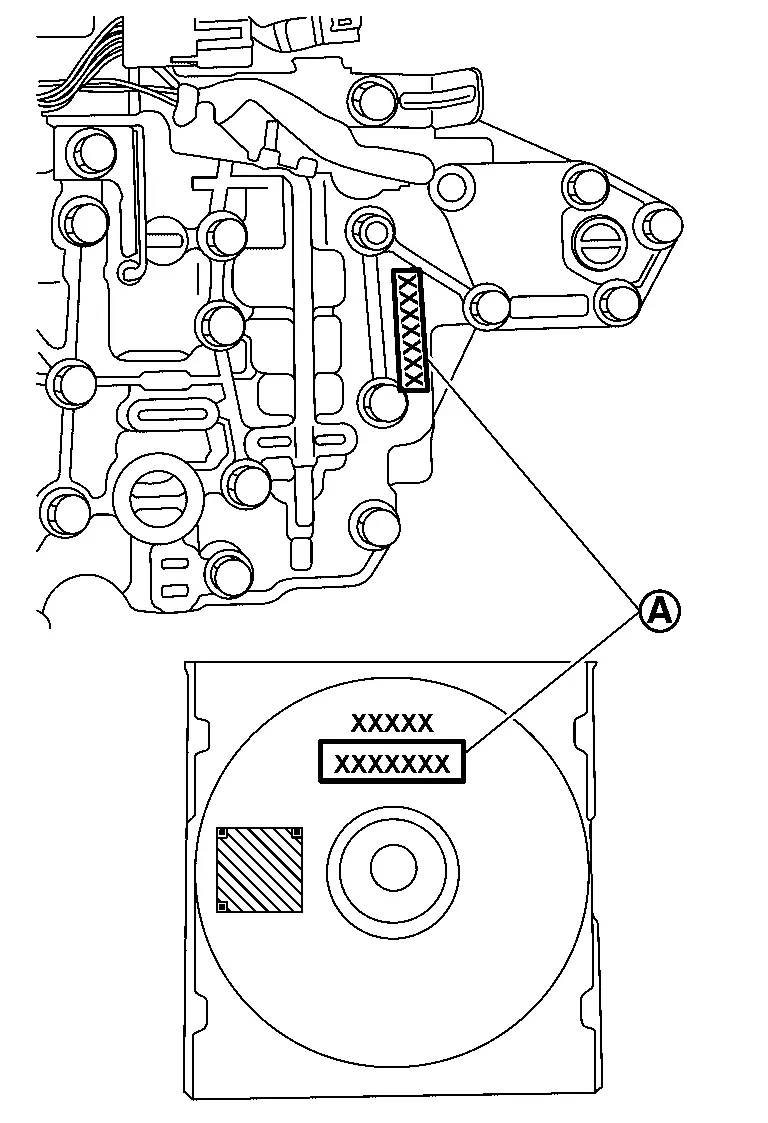
Check that the part number and serial number (A) of the new control valve are identical to those of the attached CD.
-
When replacing the control valve, attach the serial number sticker packed with it to the actuator.
 NOTE:
NOTE:
The CD provided with the new control valve contains important calibration data that must be installed with CONSULT after installation of the new control valve. Never discard the CD.
REMOVAL
| Never Reuse These Parts | Part Code | For additional information: |
|---|---|---|
| Gasket-oil pan | 31397 | Exploded View |
| Washer-drain plug | 31394E | Exploded View |
| Seal-O-ring | 31940V | Exploded View |
| Seal-O-ring | 31940VA | Exploded View |
| Seal-O-ring | 31940VC | Exploded View |
| Seal-O-ring | 31940VB | Exploded View |
| Seal-lip | 31528Q | Exploded View |
Disconnect battery negative terminal. Refer to Exploded View.
Remove shift actuator. Refer to Removal and Installation.
Remove engine under cover. Refer toExploded View .
Remove the oil pan. Refer to Removal and Installation.
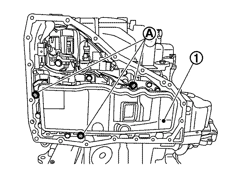
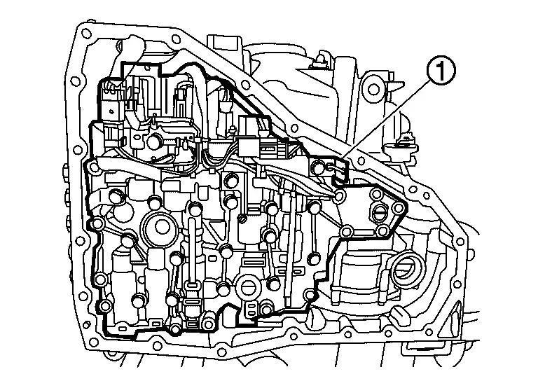
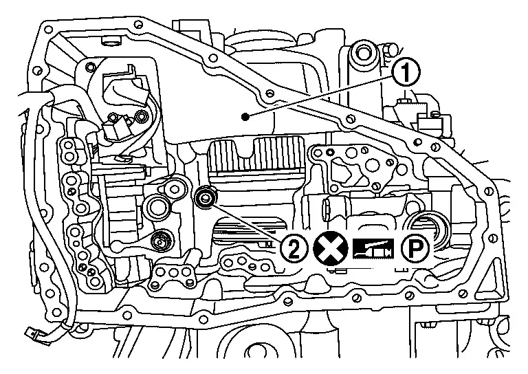
Remove oil strainer assembly mounting bolts (A) and then remove oil strainer assembly(1).
Pull one-way valve (1) out of oil strainer assembly.
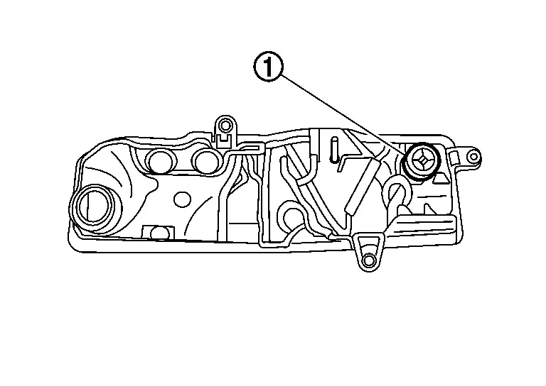
CAUTION:
While removing oil strainer assembly, one-way valve may remain on the control valve side. Be sure not to drop the one-way valve.
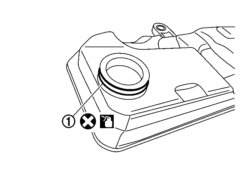
Remove O-rings (1) from one-way valve.
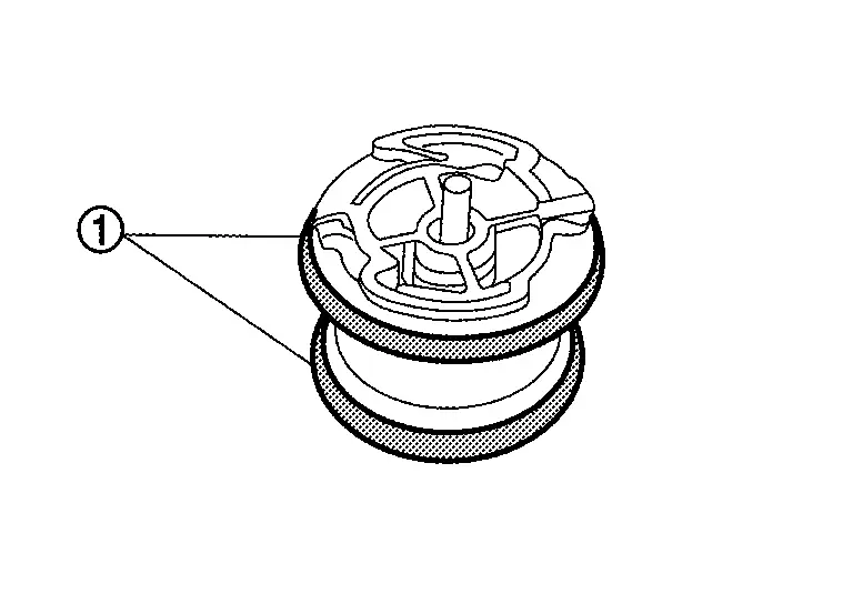
Remove O-ring (1) from oil strainer assembly.
Remove harness connectors (A) and harness clip (B).
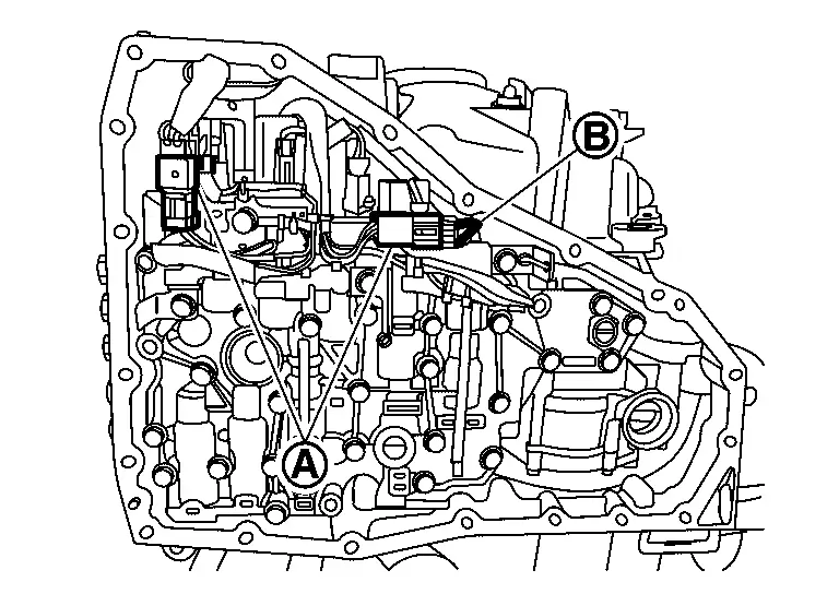
CAUTION:
Do not pull with excessive force when removing harness clip. Push tabs on the both side of harness clip properly to avoid damage.
Remove bolts ( 10 pieces) which exists on the outline of control valve (1) according to the sequence of (A), (B) and (C).
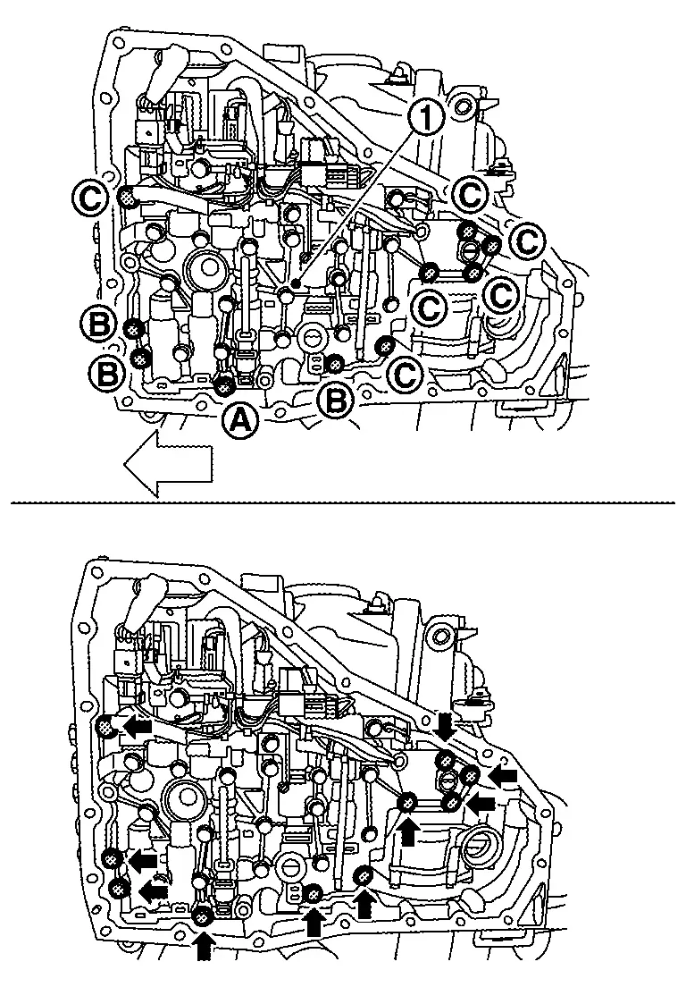
| : Nissan Ariya Vehicle front |
CAUTION:
Do not mix 3 types of bolts which were removed from control valve, and keep them separately.
| Bolt | Bolt length mm (in) | Number of bolt |
|---|---|---|
| A. | 54 (2.13) | 1 |
| B. | 44 (1.73) | 3 |
| C. | 40 (1.57) | 6 |
Remove the control valve (1) from transaxle case.
CAUTION:
Do not drop the control valve.
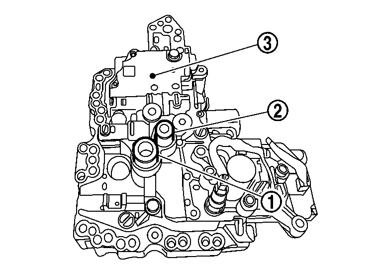
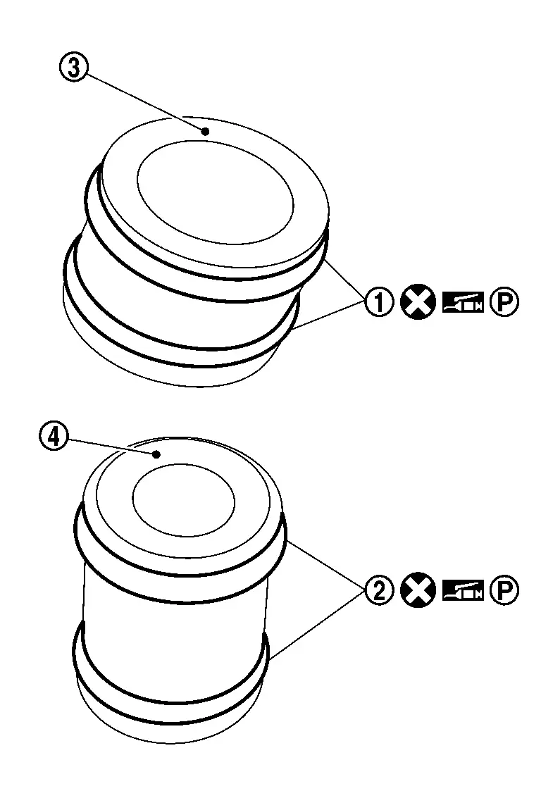
Remove tubes (1) and (2) from control valve (3).
CAUTION:
-
While removing control valve, never drop tube if it is remaining with transaxle assembly.
-
Never reuse dropped and damaged tube.
-
Place the removed control valve with the oil pressure sensor facing up to prevent damage to the oil pressure sensor.
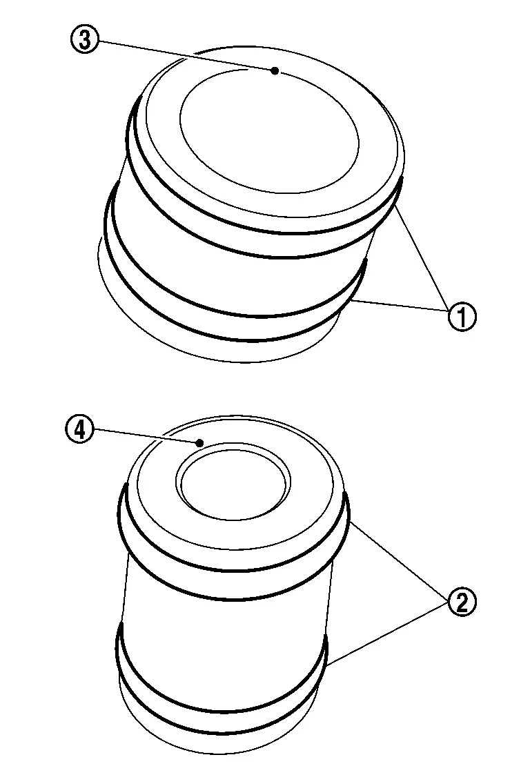
Remove O-rings (1) and (2) from tubes (3) and (4).
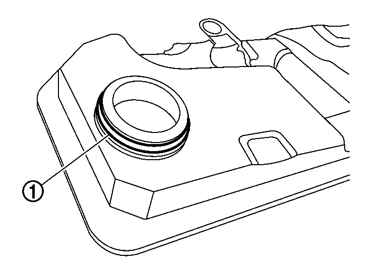
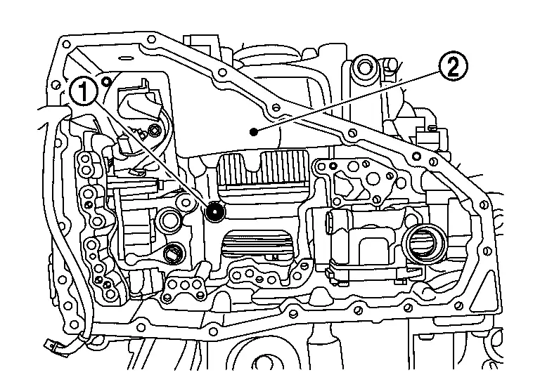
Remove lip seal (1) from transaxle assembly (2).
INSTALLATION
Install lip seal (2) to transaxle assembly (2).
CAUTION:
-
Apply petroleum jelly to lip seal.
-
Never reuse the lip seal.
Install O-rings (1) and (2) to tubes (3) and (4).
CAUTION:
-
Apply petroleum jelly to O-ring.
-
Never reuse the O-ring.
Install tubes (1) and (2) to transaxle assembly (3).
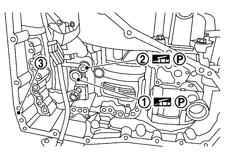
CAUTION:
-
While installing, never drop tube.
-
Never reuse dropped and damaged tube.
-
Apply petroleum jelly to the tubes to keep them in place on the transaxle case.
NOTE:
Fully push tubes to reach to the end.
Set position of manual shaft and manual valve to "N", before installing control valve.
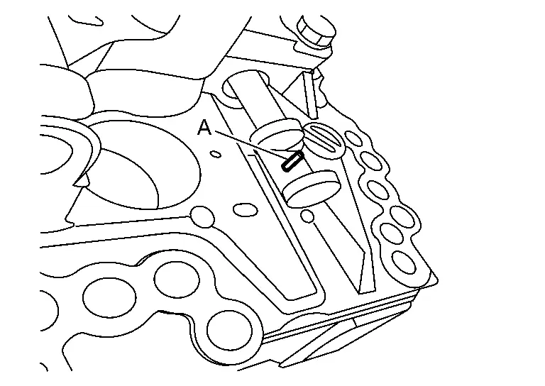
NOTE:
-
While inserting a valve body alignment tool (SST: NI-53064) (A) like a punch etc. through both holes of control valve body and manual valve, set manual valve position to "N" . After that pull out a rod.
Turn the manual shaft by CVT range switch adjuster (SST: NI-53061) to counterclockwise until it hits, return one position, and set to the N range.
-
Put align mark (A) on both of the manual shaft and the case. Use this marking as a guide when align the manual shaft with the N range.
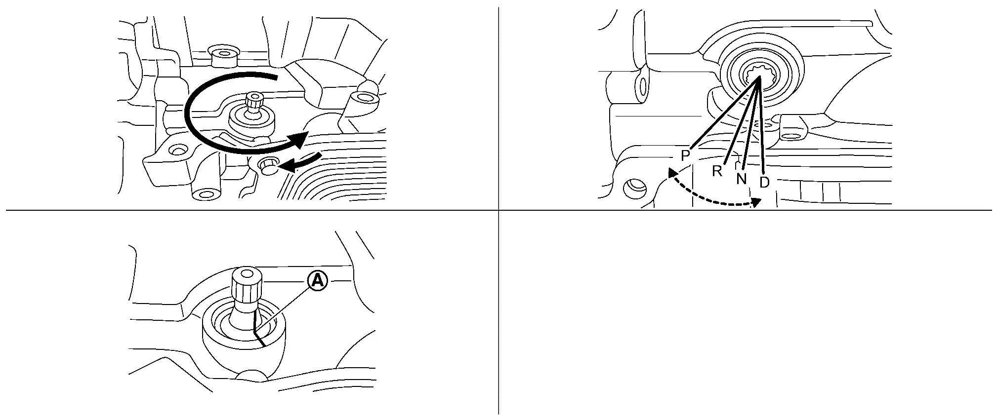
Marking (A) is made to mark the range position of the manual shaft.
-
Install the control valve (1) with mounting bolts (
10 pieces) which exists on the outline of control valve according to the sequence of (A), (B) and (C).
: Nissan Ariya Vehicle front Bolt Bolt length mm (in) Number of bolt A. 54 (2.13) 1 B. 44 (1.73) 3 C. 40 (1.57) 6 NOTE:
Install mounting bolts by hand tightening.
CAUTION:
-
There are 3 types of bolts for control valve installation. Install the bolts to appropriate position.
-
When installing the control valve, prevent it from tilting with respect to the case, and ensure positioning with the dowel pin.
-
-
Tighten ten control valve mounting bolts to the specified torque. Refer to Exploded View.
-
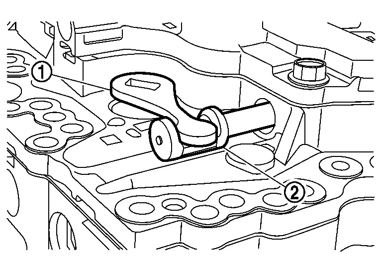
After tightening the control valve mounting bolts, check that the manual plate (1) engages with the manual valve (2) and that the manual shaft rotates normally.
Install harness connector (A) and harness clip (B).
Install two O-rings (1) to one-way valve (2).
CAUTION:
-
Apply CVT fluid to the O-rings before installation.
-
Never reuse the O-ring.
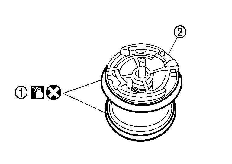
Install one-way valve (1) to oil strainer assembly.
CAUTION:
-
Apply CVT fluid to the O-rings before installation.
-
While handling oil strainer, be careful not to allow any foreign materials to enter into clean side of oil strainer to prevent drivability concerns.
-
Since internal parts are freely rotated, check all parts are located on the proper position before starting installation.
-
Check that pawls catch to lock surely.
CAUTION:
Install one-way valve with the specified direction.
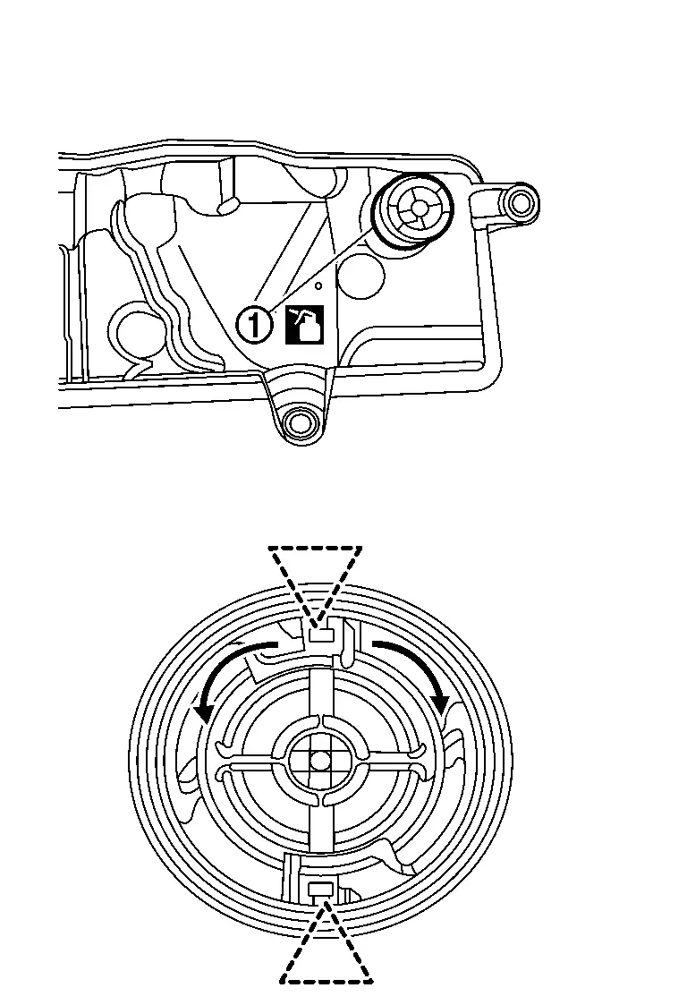
Install O-ring (1) to oil strainer assembly.
CAUTION:
-
Apply CVT fluid to the O-rings before installation.
-
While handling oil strainer, be careful not to allow any foreign materials to enter into clean side of oil strainer to prevent drivability concerns.
-
Never reuse the O-ring.
Install oil strainer assembly (1) and then tighten oil strainer assembly mounting bolts (A) to the specified torque. Refer to Exploded View.
Install oil pan. Refer to Removal and Installation.
Install shift actuator. Refer to Removal and Installation.
Install new serial number sticker (1) on shift actuator (2).
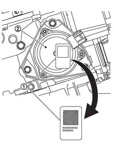
NOTE:
If sticker is not included with parts, contact Powertrain Call Center to report.
Connect battery negative terminal. Refer to Exploded View.
Fill the transaxle assembly with CVT fluid. Refer to Refilling.
Perform "ADDITIONAL SERVICE WHEN REPLACING CONTROL VALVE." Refer to Description.
Inspection and Adjustment
INSPECTION AFTER REMOVAL
Check oil pan for foreign material.
-
If a large amount of worn material is found, clutch plate may be worn.
-
If iron powder is found, bearings, gears, or clutch plates may be worn.
-
If aluminum powder is found, bushing may be worn, or chips or burrs of aluminum casting parts may enter.
Check points where wear is found in all cases.
INSPECTION AFTER INSTALLATION
Check the CVT fluid level and leakage. Refer to Inspection.
ADJUSTMENT AFTER INSTALLATION
Perform "ADDITIONAL SERVICE WHEN REPLACING CONTROL VALVE." Refer to Description.
Other materials:
Dtc/circuit Diagnosis. Door Mirror Defogger Lh
Component Function Check
CHECK DOOR MIRROR DEFOGGER LH FUNCTION
CONSULT
Ignition switch ON.
Select “Rear defogger” in “Active test” mode of "BCM".
Touch “On”.
Check that the driver side door mirror glass is getting warmer.
NOTE:
When glass is hot, never start ins ...
Power Supply and Ground Circuit
Diagnosis Procedure
CHECK ABS ACTUATOR AND ELECTRIC UNIT (CONTROL UNIT) IGNITION POWER SUPPLY
Disconnect 12V battery negative terminal.
Disconnect ABS actuator and electric unit (control unit) harness connector.
Connect 12V battery negative terminal.
Check the voltage between AB ...
Symptom Diagnosis. Intelligent Key Interlock Function Does Not Operate
Diagnosis Procedure
CHECK VEHICLE SPECIFICATION
Check if vehicle equipped navigation system.
Is equipped navigation system?
YES>>
GO TO 2.
NO>>
GO TO 3.
CHECK LOG-IN FUNCTION
Check log-in function. Refer to System Description.
Is the inspection result normal?
YES>>
G ...