Nissan Rogue (T33) 2021-Present Service Manual: Calibrating Camera Image (intelligent Around View Monitor)
Without Propilot Assist 2.1
Work Procedure
-
Calibration must be performed after removing/replacing the cameras, removing parts (e.g. front grille, door mirror, and others) mounted on the cameras, or replacing the around view monitor control unit.
-
The use of CONSULT is required to perform calibration or writing of calibration results to the around view monitor control unit.
-
Align the white lines on the road near the Nissan Ariya vehicle at the boundary of each camera image by this camera calibration. The white lines far from the vehicle may not be aligned at the boundary of each camera image. The farther the line, the greater the difference is.
-
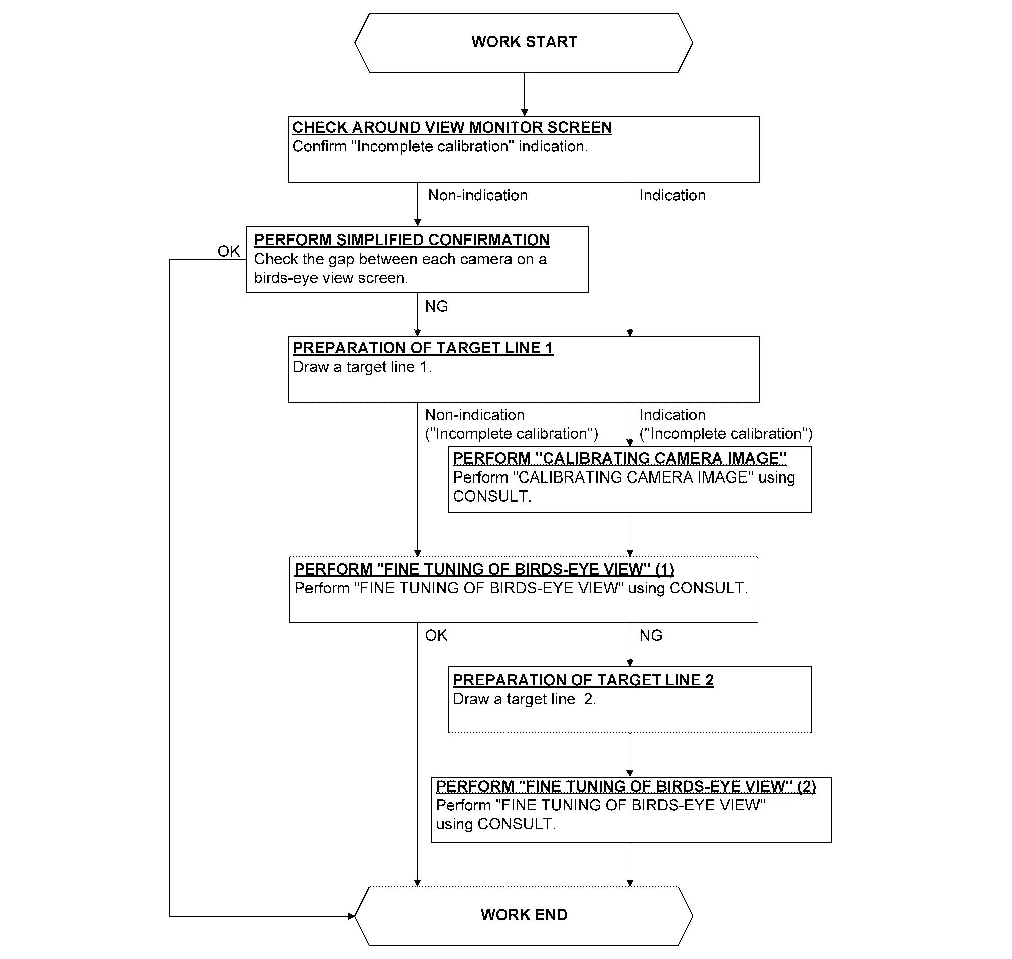
Following the flowchart shown in the figure, perform the calibration.
CAUTION:
When around view monitor control unit is replaced, Write the calibration data before performing this calibration. Refer to Work Procedure.
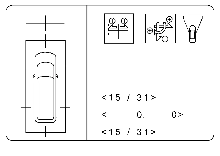
CHECK AROUND VIEW MONITOR SCREEN
Check that there is no indication of вҖңIncomplete calibrationвҖқ.

 NOTE:
NOTE:
View in the incomplete calibration state is indicated by вҖң вҖқ on the around view monitor.
Is the вҖңIncomplete calibrationвҖқ display visible?
YES>>GO TO 3.
NO>>GO TO 2.
PERFORM SIMPLIFIED CONFIRMATION BY BIRDS-EYE VIEW SCREEN
Check the gap between each camera image on a birds-eye view screen.
Is the gap between each camera image exist?
YES>>GO TO 3.
NO>>WORK END
PREPARATION OF TARGET LINE 1
NOTE:
-
If a target line is narrow, it is hard to confirm it with around view monitor screen. The width of the target line recommends an approximately 5.0 - 10.0 cm (1.97 - 3.94 in).
-
It is easy to confirm a target line on a around view monitor screen when draw a target line with a color opposite to a working floor.
Example
-
Floor is blue: target line is yellow
-
Floor is green: target line is red
-
Preparation of target line 1
-
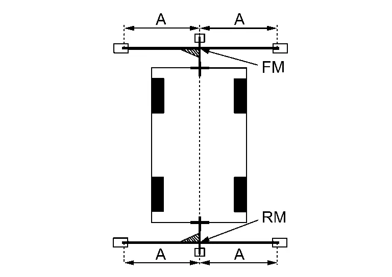
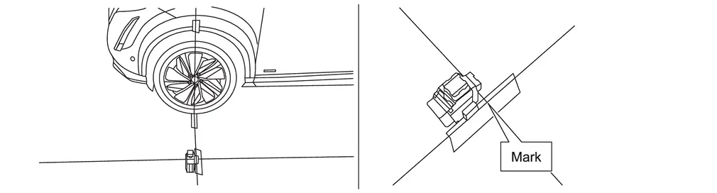
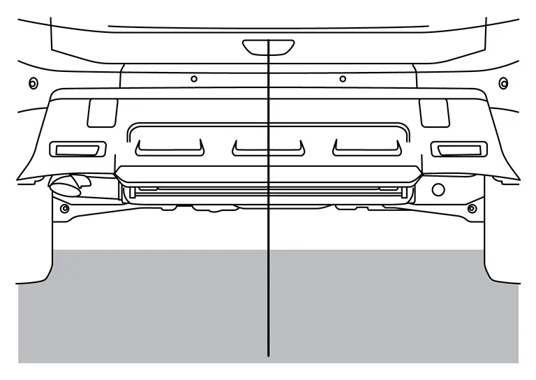
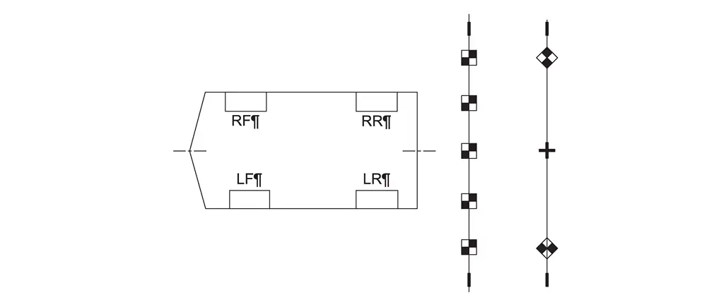
Hang a string with a weight as shown in the figure. Put the points FM0, RM0 (mark) on the ground at the center of the Nissan Ariya vehicle front end and rear end with white packing tape or a pen.
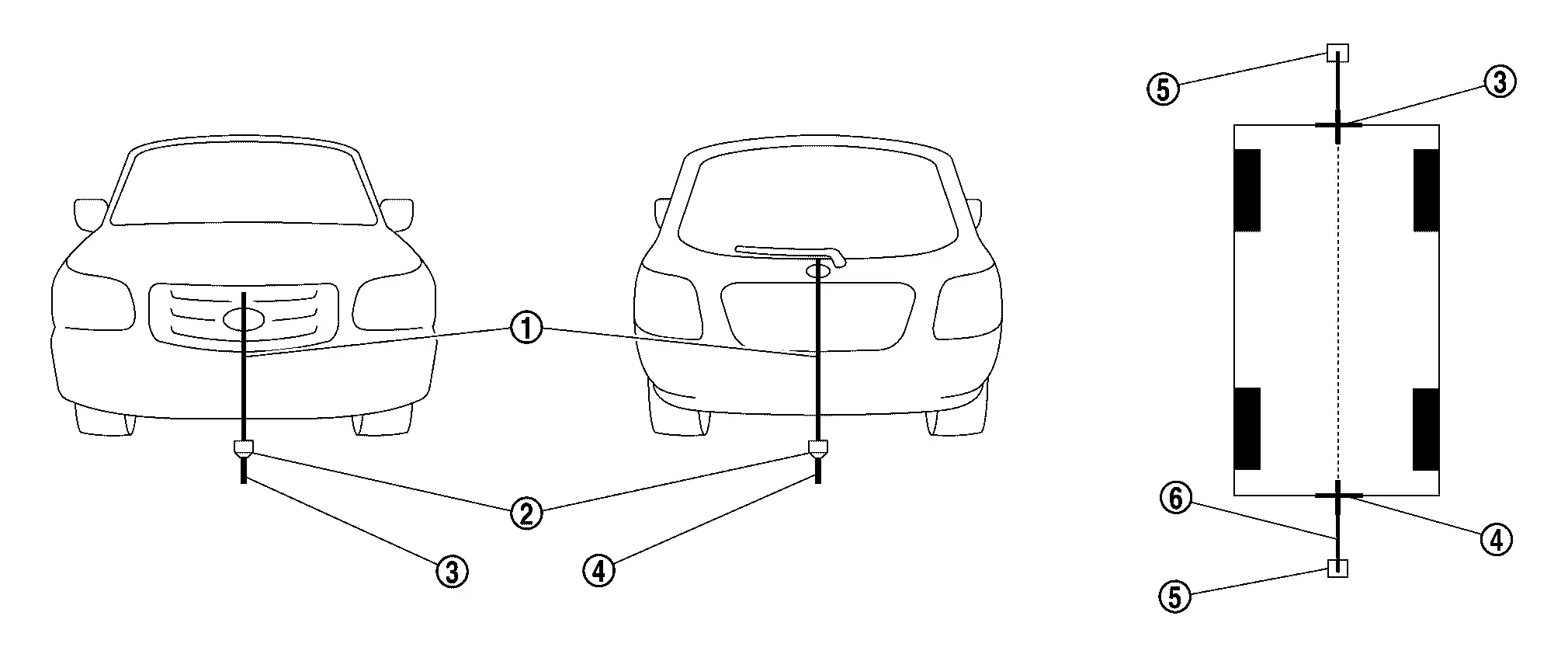
1. Thread 2. Weight 3. Point FM0 (mark) 3. Point RM0 (mark) 4. Packing tape (to fix the vinyl string) 5. Vinyl string -
Route the vinyl string under the Nissan Ariya vehicle, and then pull and fix it on the point approximately 1.0 m (39.9 in) to the front and rear of the vehicle through the points FM0 and RM0 using packing tape.
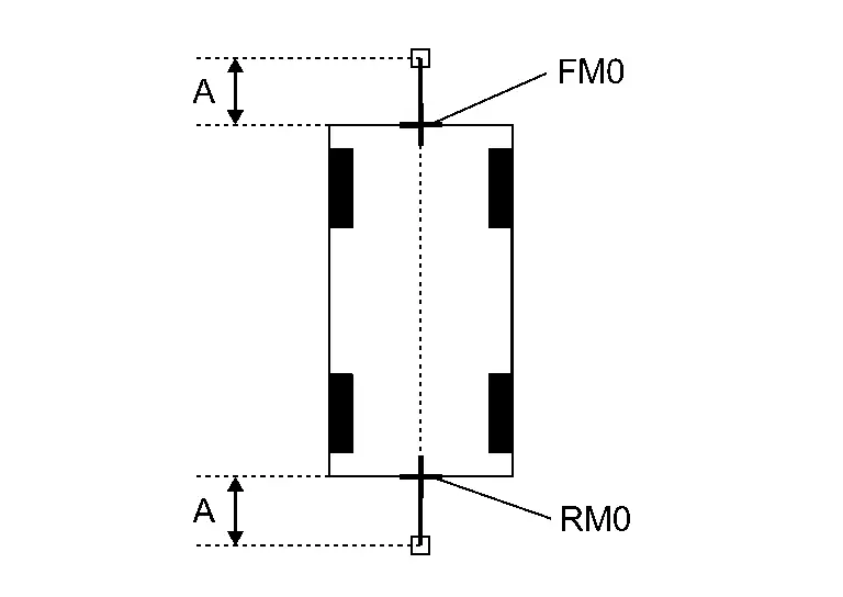
A : Approx.1.0 m (39.9 in) -
Put the points FM and RM (mark) 75 cm (29.5 in) from the points FM0 and RM0 individually.
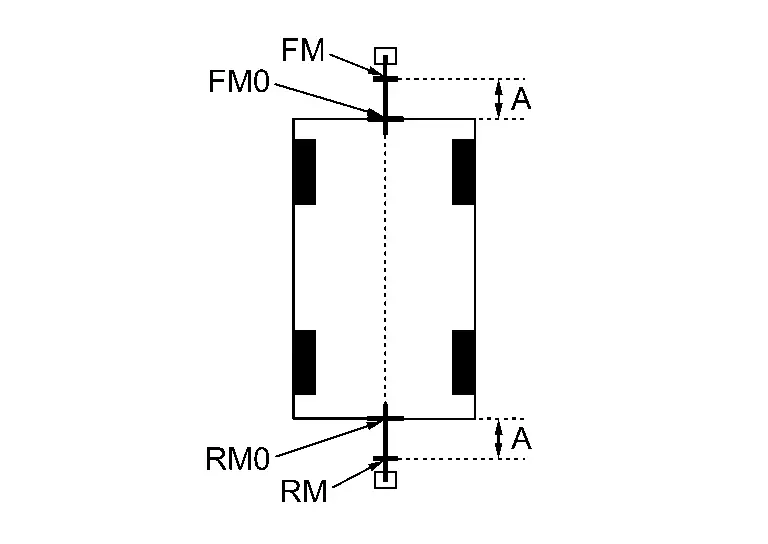
A : Approx. 75 cm (29.5 in) -
Route the vinyl string through the points FM and RM using a triangle scale, and then fix it at approximately 1.5 m (59.0 in) on both sides with packing tape.
A Approx. 1.5 m (59.0 in) -
Put the points FL, FR, RL, and RR (mark) to both right and left [Nissan Ariya vehicle width / 2 + 30 cm (11.8 in)] from the points FM and RM.
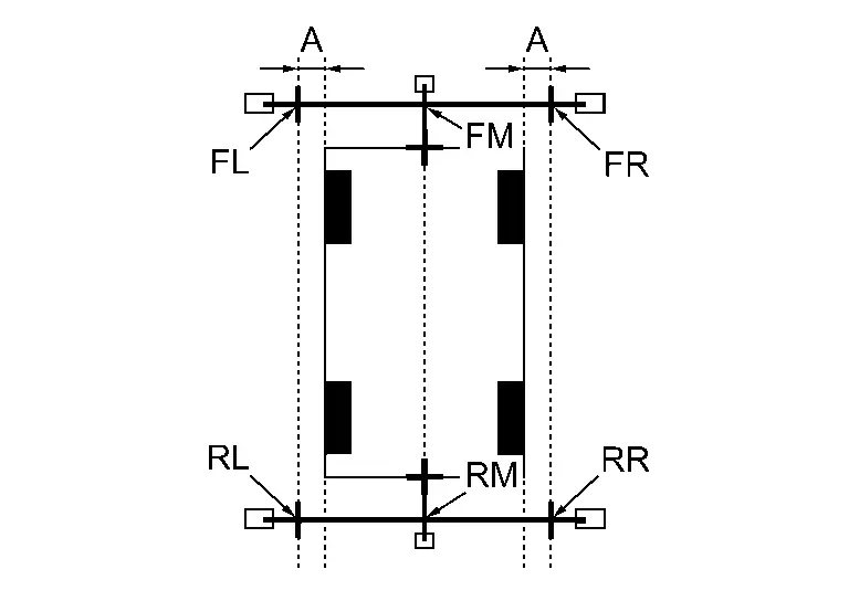
A : Approx. 30 cm (11.8 in) -
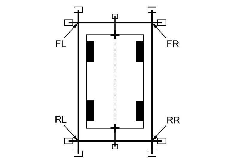
Draw the lines of the points FL вҖ“ RL and FR вҖ“ RR with vinyl string, and fix it with packing tape.
-
Put a mark on the center of each axle
 ,
draw vertical lines to the lines of the points FL вҖ“ RL and FR вҖ“ RR from
the marks on the center of the axle using a triangle scale, and then
fix the lines using packing tape.
,
draw vertical lines to the lines of the points FL вҖ“ RL and FR вҖ“ RR from
the marks on the center of the axle using a triangle scale, and then
fix the lines using packing tape.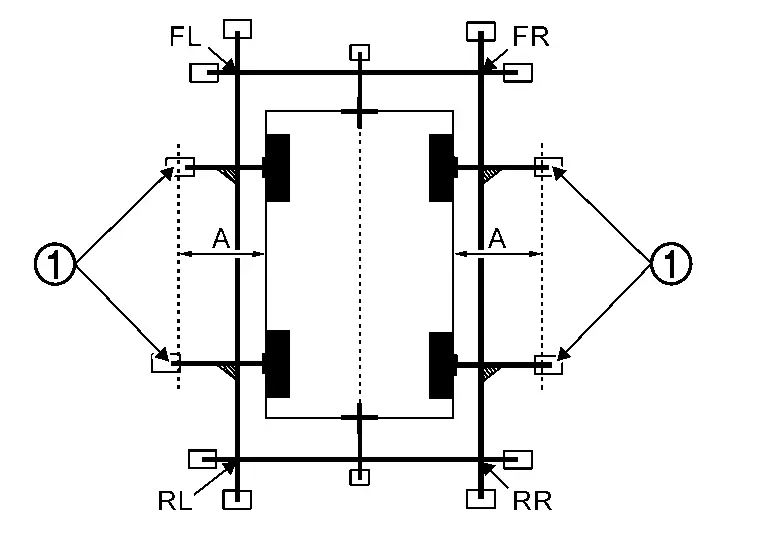
A : Approx. 60 cm (23.6 in)
Indication of вҖңIncomplete calibrationвҖқ>>
GO TO 4.
No indication of вҖңIncomplete calibrationвҖқ>>GO TO 5.
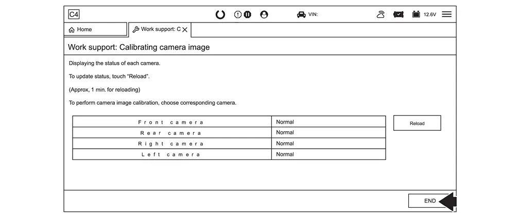
PERFORM вҖңCALIBRATING CAMERA IMAGEвҖқ
 With CONSULT
-
Select вҖңCALIBRATING CAMERA IMAGEвҖқ in вҖңWork SupportвҖқ mode of вҖңAVMвҖқ using CONSULT.
NOTE:
In random order, perform the operation for all cameras for which un-match display
 appears.
-
Front camera: вҖңCALIBRATING CAMERA IMAGE (FRONT CAMERA)вҖқ
-
Side camera RH: вҖңCALIBRATING CAMERA IMAGE (PASS-SIDE CAMERA)вҖқ
-
Side camera LH: вҖңCALIBRATING CAMERA IMAGE (DR-SIDE CAMERA)вҖқ
-
Rear camera: вҖңCALIBRATING CAMERA IMAGE (REAR CAMERA)вҖқ
-
-
Perform вҖңCALIBRATING CAMERA IMAGEвҖқ as per the following procedure.
-
On the adjustment screen of each camera, adjust the parameter by touching the вҖңAXIS XвҖқ, вҖңAXIS YвҖқ, and вҖңROTATEвҖқ to place the calibration marker shown on the camera screen on the target line drawn on the ground.
-
On the adjustment screen of each camera, operate вҖң+вҖқ and вҖң-вҖқ of вҖңMagnify/ReduceвҖқ, so that images on screen of target line and calibration maker are aligned.
-
-
Touch вҖңAPPLYвҖқ on the CONSULT screen. вҖңWriting...вҖқ is displayed and adjustment results are shown on the camera screen.
CAUTION:
Check that вҖңWriting...вҖқ is displayed. Do never perform other operations while вҖңWriting...вҖқ is displayed.
-
Touch вҖңOKвҖқ on the CONSULT screen. вҖңPRCSNGвҖқ is displayed and adjustment results are written to the around view monitor control unit.
CAUTION:
Check that вҖңPRCSNGвҖқ is displayed. Never perform other operations while вҖңPRCSNGвҖқ is displayed.
>>
GO TO 5.
PERFORM вҖңFINE TUNING OF BIRDS-EYE VIEWвҖқ (1)
With CONSULT
-
Select вҖңFINE TUNING OF BIRDS-EYE VIEWвҖқ in вҖңWork SupportвҖқ mode of вҖңAVMвҖқ using CONSULT.
-
Perform вҖңFINE TURNING OF BIRDS-EYE VIEWвҖқ as per the following procedure.
CAUTION:
Perform adjustment operation slowly because approximately 1 second is required for changing image on screen.
NOTE:
Touch вҖңSELECTвҖқ on CONSULT screen and select camera position for adjustment.
-
Operate вҖң+вҖқ and вҖңвҖ“вҖқ of вҖңAXIS XвҖқ, вҖңAXIS YвҖқ, and вҖңROTATEвҖқ, so that images on screen of target line on the ground and marker are aligned between each camera.
-
Operate вҖң+вҖқ and вҖңвҖ“вҖқ of вҖңMagnify/ReduceвҖқ, so that images on screen of target line on the ground and marker are aligned between each camera.
-
-
Touch вҖңAPPLYвҖқ on the CONSULT screen. вҖңWriting...вҖқ is displayed and adjustment results are shown on the camera screen.
CAUTION:
Check that вҖңWriting...вҖқ is displayed. Do never perform other operations while вҖңWriting...вҖқ is displayed.
-
Touch вҖңOKвҖқ on the CONSULT screen. вҖңPRCSNGвҖқ is displayed and adjustment results are written to the around view monitor control unit.
CAUTION:
-
Check that вҖңPRCSNGвҖқ is displayed. Never perform other operations while вҖңPRCSNGвҖқ is displayed.
-
After touching the вҖңOKвҖқ, never touch screen other than the вҖңBACKвҖқ.
-
NOTE:
-
The adjustment value is cancelled in this mode by performing вҖңInitialize Camera Image CalibrationвҖқ.
Is the gap between the each camera image normal?
YES>>WORK END
NO>>GO TO 6.
PREPARATION OF TARGET LINE 2
Draw target line 2  at the position of the approximately 1.0 m (39.9 in) outside from target line 1 (1) which established by procedure 2.
| A | : Approx.1.0 m (39.9 in) |
NOTE:
The white lines far from the Nissan Ariya vehicle may not be aligned at the boundary of each camera image. The farther the line, the greater the difference is. can adjust it in detail by drawing a target line 2.
>>
GO TO 7.
вҖңPERFORM вҖңFINE TUNING OF BIRDS-EYE VIEWвҖқ (2)
NOTE:
This adjustment merges the boundary line of each camera image which was not able to adjust by вҖңFINE TUNING OF BIRDS-EYE VIEWвҖқ (1).
With CONSULT
-
Select вҖңFINE TUNING OF BIRDS-EYE VIEWвҖқ in вҖңWork SupportвҖқ mode of вҖңAVMвҖқ using CONSULT.
-
Perform вҖңFINE TURNING OF BIRDS-EYE VIEWвҖқ as per the following procedure.
CAUTION:
Perform adjustment operation slowly because approximately 1 second is required for changing image on screen.
NOTE:
Touch вҖңSELECTвҖқ on CONSULT screen and select camera position for adjustment.
-
Confirm the gap of the boundary of target line 2 between the camera image and operate вҖң+вҖқ and вҖңвҖ“вҖқ of вҖңAXIS XвҖқ, вҖңAXIS YвҖқ, вҖңROTATEвҖқ and вҖңMagnify/ReduceвҖқ, and adjust the gap of the target line 2 boundary.
-
-
Touch вҖңAPPLYвҖқ on the CONSULT screen. вҖңWriting...вҖқ is displayed and adjustment results are shown on the camera screen.
CAUTION:
Check that вҖңWriting...вҖқ is displayed. Never perform other operations while вҖңWriting...вҖқ is displayed.
-
Touch вҖңOKвҖқ on the CONSULT screen. вҖңPRCSNGвҖқ is displayed and adjustment results are written to the around view monitor control unit.
CAUTION:
-
Check that вҖңPRCSNGвҖқ is displayed. Never perform other operations while вҖңPRCSNGвҖқ is displayed.
-
After touching the вҖңOKвҖқ, never touch screen other than the вҖңBACKвҖқ.
-
NOTE:
-
The adjustment value is cancelled in this mode by performing вҖңInitialize Camera Image CalibrationвҖқ.
>>
WORK END
With Propilot Assist 2.1
Work Procedure
-
Perform camera calibration and perform parameter writing to the around view monitor control unit, after removal/ installation or replacement of each camera or camera mounting parts (front bumper molding center, door mirror, or others), or replacement of around view monitor control unit.
| Parts name | Operation | Operation | |
| Replacement | Removal | ||
| Front camera | x | x | Camera calibration |
| Front bumper molding center | x | x | |
| Side camera | x | x | |
| Door mirror ASSY | x | x | |
| Rear camera | x | x | |
| Back door ASSY | x | x | |
PREPARATION
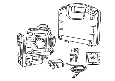
REQUIRED TOOLS
New or replacement Essential Tools are available from Tech Mate online: www.techmatetools.com, or by phone: 1-833-397-3493.
-
Laser level (NI-53373)
-
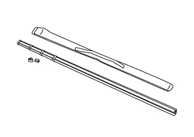
ADAS Calibration Rod (NI-53371)
-
Calibration Targets (NI-53378)

The following required tools can be obtained from any local retailer.
-
CarpenterвҖҷs square (minimum 12 in. long leg)
-
PainterвҖҷs tape [minimum width 1 7/8 in. (48 mm)]
-
Permanent marker
-
Chalk line tool
-
Tape measure capable of measuring a minimum of 5 meters (must have metric markings)
PERFORM SELF-DIAGNOSIS
Perform вҖңAll DTC ReadingвҖқ with CONSULT.
Is DTC detected?
Detecting DTC other than AVM DTCs>>Perform a corresponding diagnosis from the DTC list first.
Detected AVM DTCs.>>GO TO 2.
CHECK REPLACED PARTS 1
Check replaced parts.
NOTE:
When replacing only the around view monitor control unit, each camera memorizes calibration data, calibration by installing the target is unnecessary.
One or more cameras>>
GO TO 3.
AVM>>GO TO 4.
PARAMETER WRITING (All CAMERA)
Select "Work support", "Parameter writing (All camera)" and write camera parameter.
NOTE:
-
If the CONSULT PC and VI remain connected, the Nissan Ariya vehicle alarm may sound during the 10 minute wait.
-
The CONSULT PC can be shut down and the VI removed to avoid the possibility of the Nissan Ariya vehicle alarm sounding during the 10 minute wait.
-
If the CONSULT PC is not shut down and the VI is not removed, use the key fob to stop the alarm, and then finish the 10 minute wait.
The parameters written successful?
YES>>GO TO 4.
NO>>-
Turn the Nissan Ariya vehicle OFF.
-
Close and lock all the doors.
-
Move the keys away from the vehicle a minimum of 30 ft.
-
Wait 10 minutes.
-
Put the Nissan Ariya vehicle in READY mode.
-
Select Retry.
-
Once the Parameter writing is successful, GO TO 4.
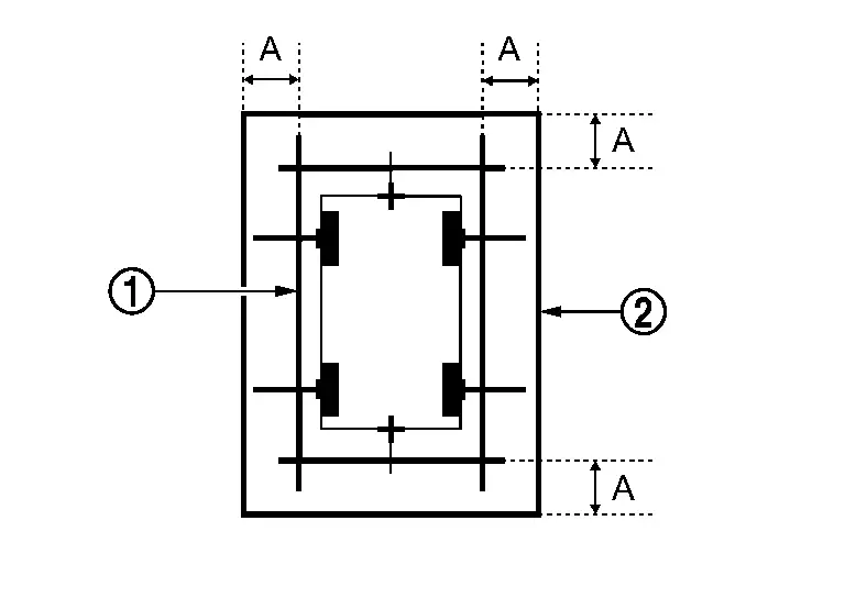
CHECK FOR ANY CAMERAS THAT REQUIRES CALIBRATION
-
Confirm each camera image is displaying an actual steady image on the screen by cycling through the CAMERA button beside the display (the image may still look like it needs to be aimed).
-
If there is a solid color (pink, green, gray, etc) and/or a flashing screen, one or more AVM cameras still require replacement.
-
Check each camera, one by one, by disconnecting the camera harnesses to determine the source of the solid color and/or flashing screen, and then repair accordingly.
-
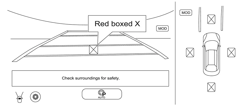
-
Any camera(s) that have a red boxed X will require calibration. Proceed to step PERFORM CALIBRATION to start marking the center point for each wheel and tire assembly.
NOTE:
All four (4) cameras in Figure require calibration.
-
If there are no red boxed XвҖҷs on the screen, the image on the screen appears OK, and any DTCs present are PAST, camera calibration is not required. Skip to steps 21 in Procedure 11.
>>
GO TO 5.
CAMERA CALIBRATION PREPARATION
-
Check tire pressure and adjust to regular pressure.
-
Nissan Ariya Vehicle in no-load condition.
-
Empty the vehicle.
-
Select shift position P and release parking brake.
-
Open door mirror.
-
Clean each camera.
-
Secure workspace for calibration according to the camera.
-
A large area, free from obstructions, is needed to calibrate each camera.
-
A strong Wi-Fi or mobile hotspot is required.
-
The floor should be as level as possible (drains are not allowed).
-
The floor needs to be clean and dry, otherwise the tape will not stick, and markings will not be clear.
-
The hood must remain closed.
-
The 12V battery must be in good condition and maintained using an appropriate battery charger during programming.
-
All measurements must be done in millimeters (mm).
-
Fans should be avoided for target stability and laser level.
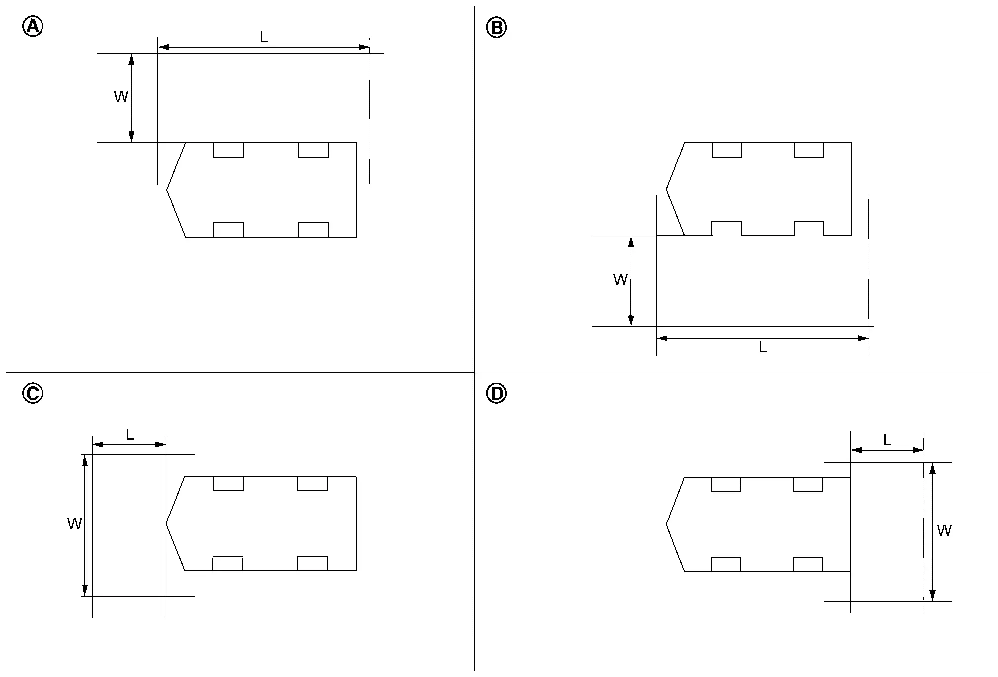

Driver camera calibration
L: 5000 mm (about 16.4 ft)
W: 3000 mm (about 9.84 ft)
Passenger side camera calibration
L: 5000 mm (about 16.4 ft)
W: 3000 mm (about 9.84 ft)
Front camera calibration
L: 3000 mm (about 9.84 ft)
W: 5000 mm (about 16.4 ft)
Rear camera calibration
L: 3000 mm (about 9.84 ft)
W: 5000 mm (about 16.4 ft)
>>
GO TO 6.
PREPARATION OF CALIBRATION TARGET
-
Prepare fourteen sheets of white paper and black paper, respectively, with dimensions of 200 mm (7.87 in) X 200 mm (7.87 in) to create a left target and right target.
-
Tape two sheets of black paper and two sheets of white paper together to make a target of 400 mm (15.75 in) X 400 mm (15.75 in).
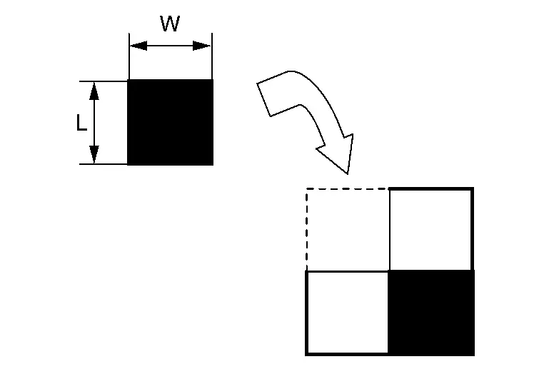
L : 200 mm (about 7.87 in) W : 200 mm (about 7.87 in) NOTE:
Use transparent tape.
-
Following step 2, create 6 targets (7 targets required).
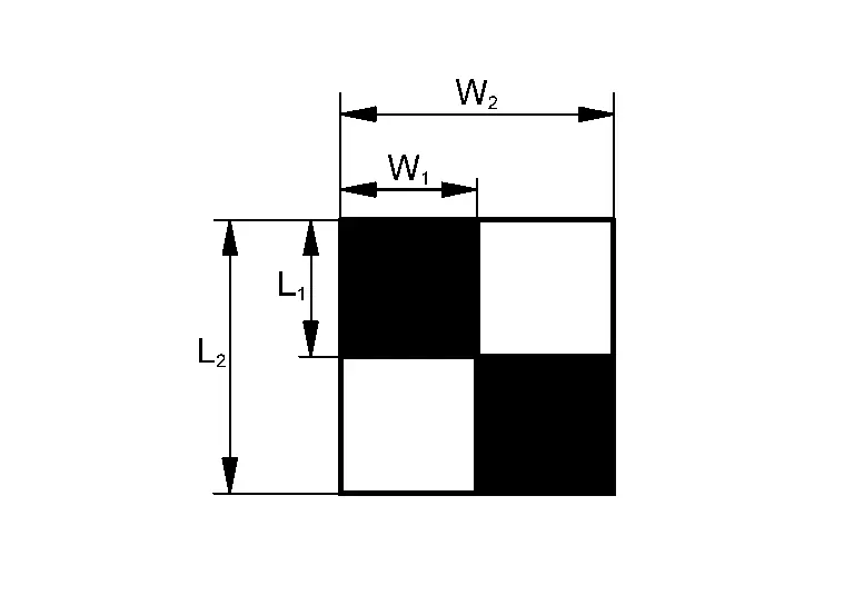
L1 : 200 mm (7.87 in) L2 : 400 mm (15.75 in) W1 : 200 mm (7.87 in) W2 : 400 mm (15.75 in) NOTE:
Never apply tape to the target surface.
>>
GO TO PERFORM CALIBRATION
PERFORM CALIBRATION
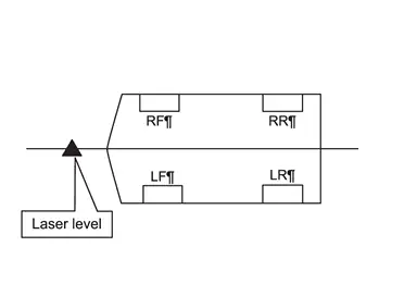
MARKING THE CENTER POINT OF THE WHEEL AND TIRE ASSEMBLIES
-
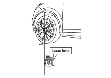
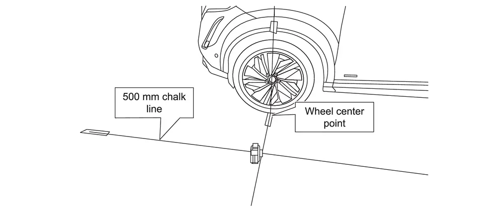
Place the laser level approximately 800 mm (31.5 in.) from the wheel and tire assembly.
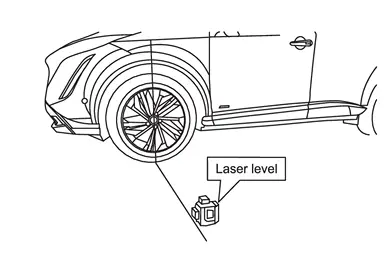
-
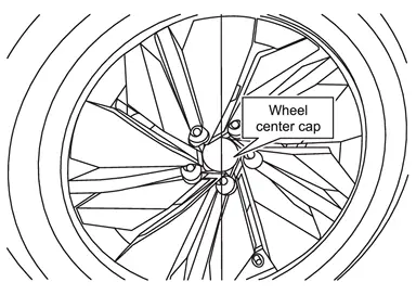
Align the vertical laser line to the wheel axle centerline (wheel center cap).
-
Mark the wheel arch and the floor near the tire.
NOTE:
The use of painterвҖҷs tape helps capture the markings on the Nissan Ariya vehicle and floor.
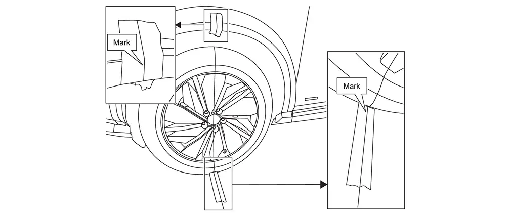
-
Move the laser so it is about 45В° and approximately 800 mm (31.5 in.) from the wheel axle centerline.
NOTE:
The laser level can be either to the left or right of the wheel and tire assembly.
-
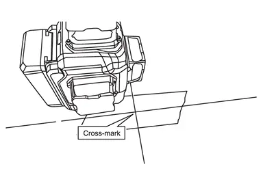
Line up the vertical laser line to the mark on the wheel arch
and then mark the floor with a cross-mark. This is the center point of the wheel and tire assembly .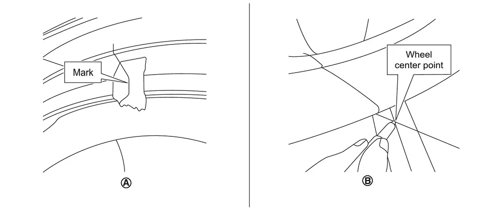 NOTE:
NOTE:
-
The vertical laser line must line up with the line on the wheel arch, not the wheel center cap
. -
To ensure the wheel center mark is not covered up by the bulge in the tire, ensure the Nissan Ariya vehicle is parked on a completely level area and the tires are properly inflated.
-
-
Repeat steps 1 - 5 starting, marking the center points at all four (4) wheel and tire assemblies.
>>
GO TO 2.
CHECK CAMERA
Check the camera to be calibrated.
Left side camera or right-side camera.>>
GO TO 3.
Front or rear camera.>>GO TO 6.
PLACING CALIBRATION TARGETS FOR THE DRIVER (LH) AND/OR PASSENGER (RH) SIDE CAMERAS
NOTE:
Steps 1 - 13 and the related figures show the driver (LH) side of the Nissan Ariya vehicle. The passenger (RH) side is similar. If the AVM Control Module was replaced, steps 1 - 13 must be performed for both the driver and passenger side cameras.
-
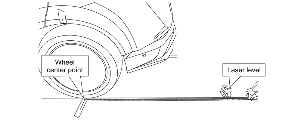
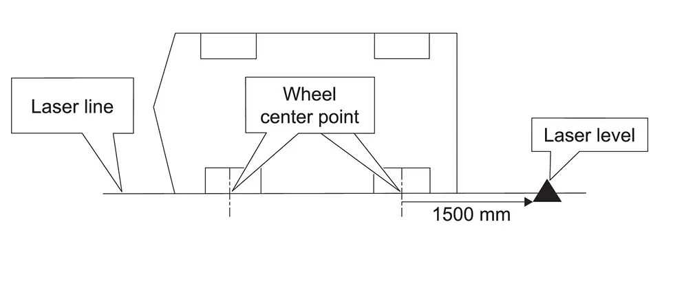
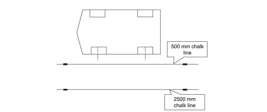
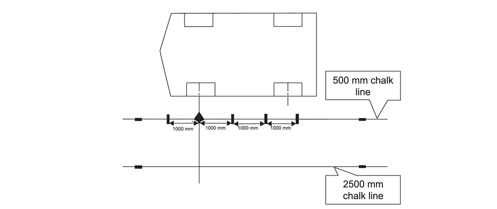
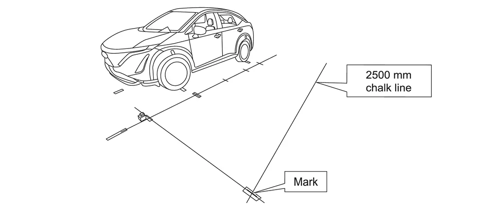
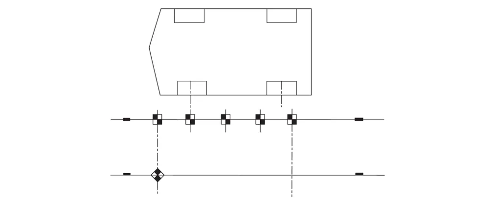
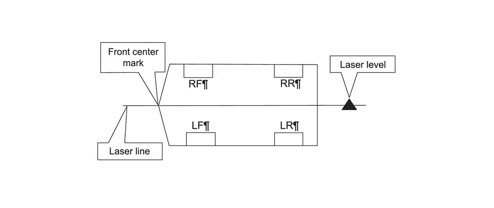
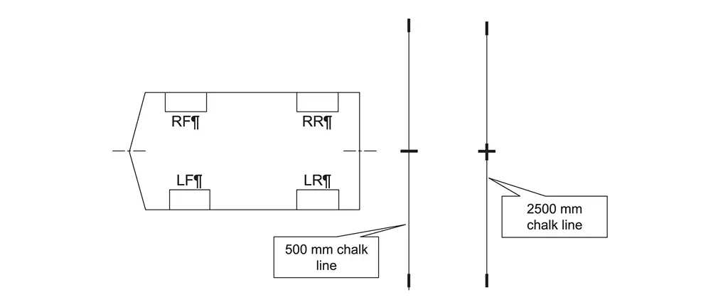
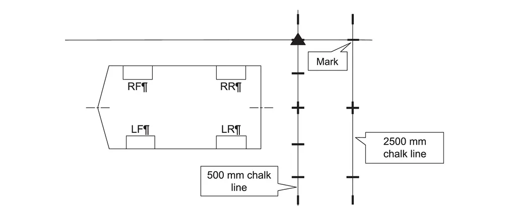
Place the laser level approximately 1500 mm (59 in.) behind the rear wheel, and then align the laser level so that the laser line is perfectly centered through the center points of both wheel and tire assemblies marked in step 1. of 5.
-
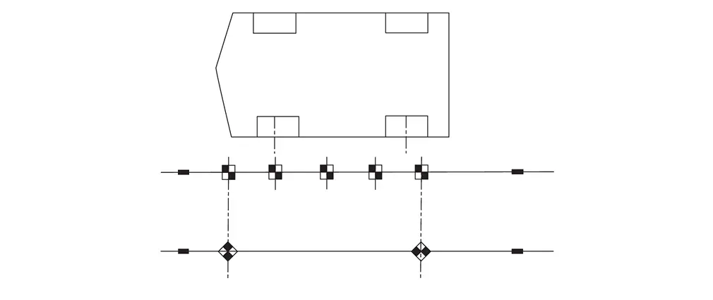
Activate a second vertical laser line (90В° to the original laser line), and then mark a line at 500 mm (about 1.64 ft) and 2500 mm (about 8.2 ft) from the original laser line, as shown.
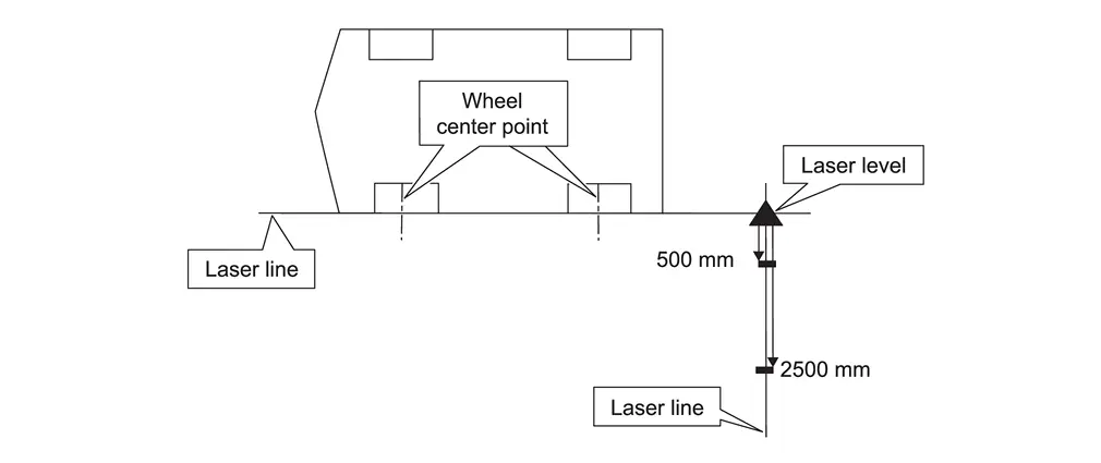
-
Repeat steps 1 - 2 starting, for the front of the Nissan Ariya vehicle.
-
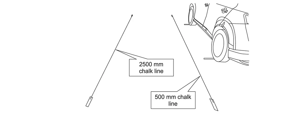
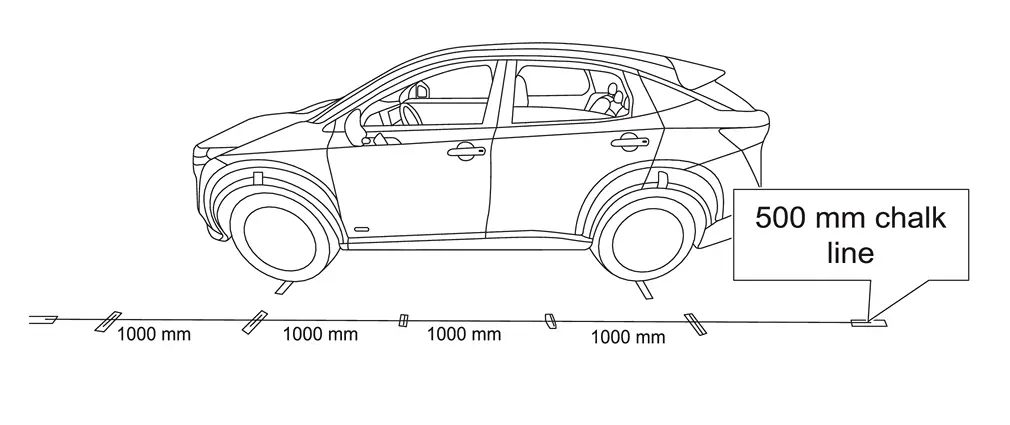
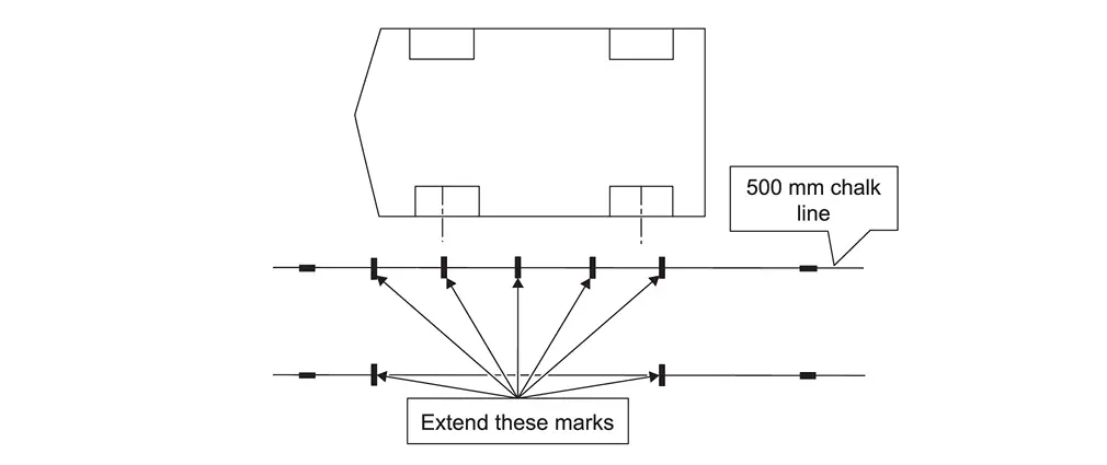
Use a chalk line tool to make a line between the 500 mm (about 1.64 ft) and 2500 mm (about 8.2 ft) marks, as shown.
-
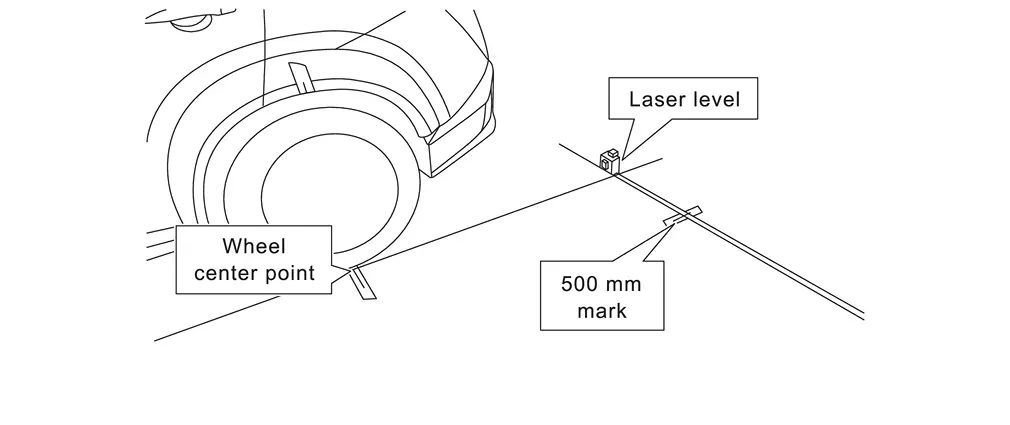
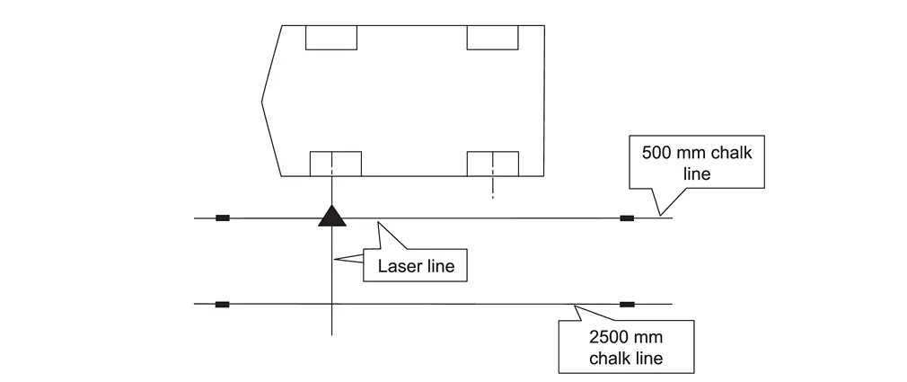
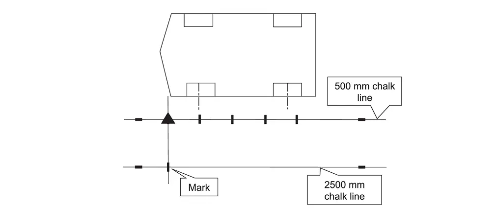
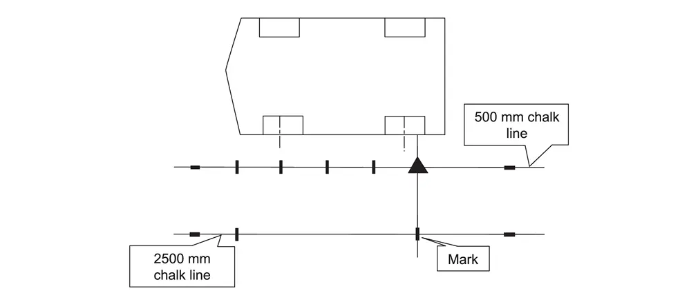
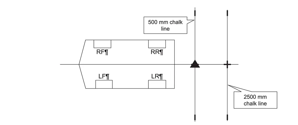
Place the laser level with both vertical lines activated and align one laser line with the 500 mm (about 1.64 ft) chalk line and align the other laser line to the center point on the front driver (LH) side wheel, as shown in Figure.
NOTE:
The laser line must be perfectly aligned with the 500 mm (about 1.64 ft) chalk line.
-
Place a mark on the floor below the laser line.
-
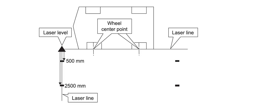
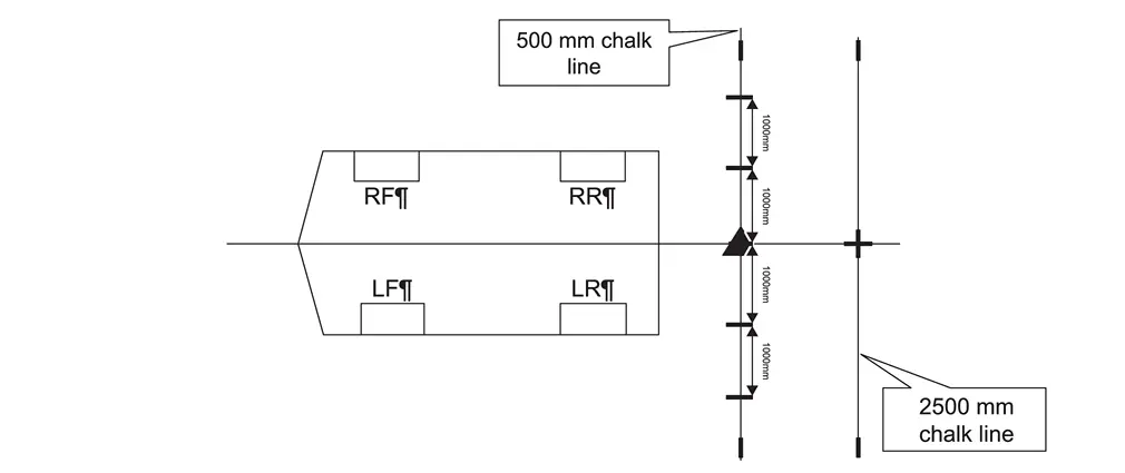
Measure and mark 1000 mm (about 3.28 ft) increments, as shown in Figure.
-
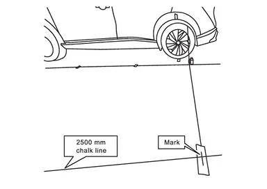
Move the laser level to the position shown in Figure, and then make a mark on the 2500 mm (about 8.2 ft) chalk line.
NOTE:
The laser line must be perfectly aligned with the 500 mm (about 1.64 ft) chalk line.
-
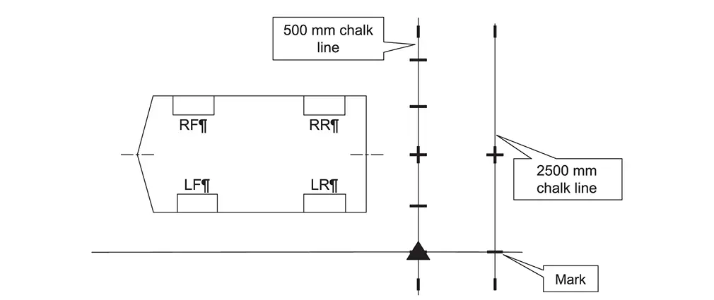
Move the laser level to the position shown in Figure, and then make a mark on the 2500 mm (about 8.2 ft) chalk line.
NOTE:
The laser line must be perfectly aligned with the 500 mm (about 1.64 ft) chalk line.
-
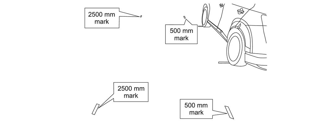
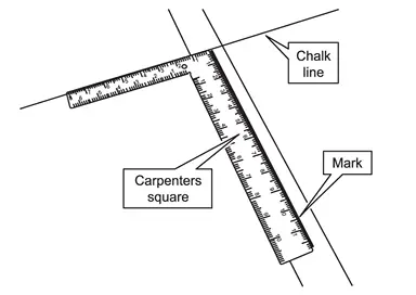
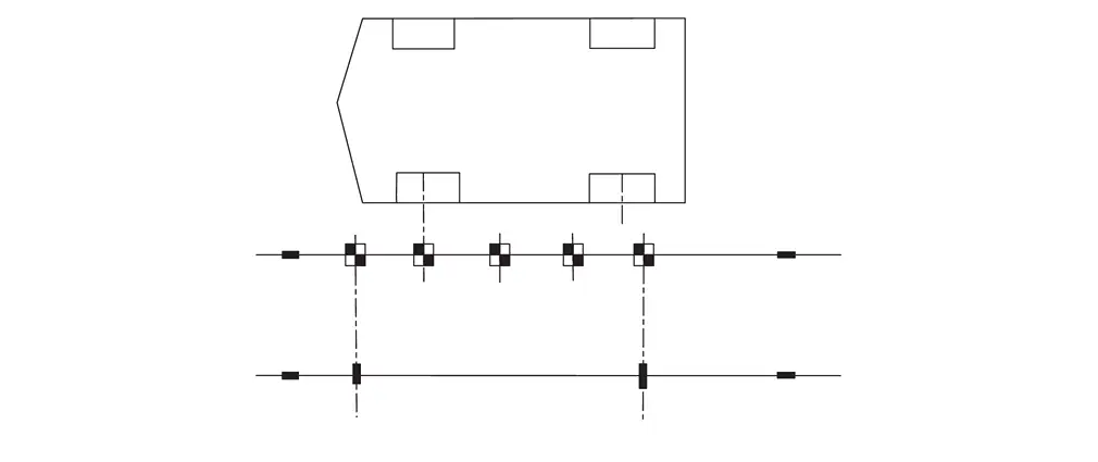
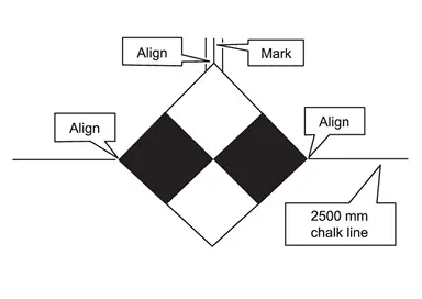
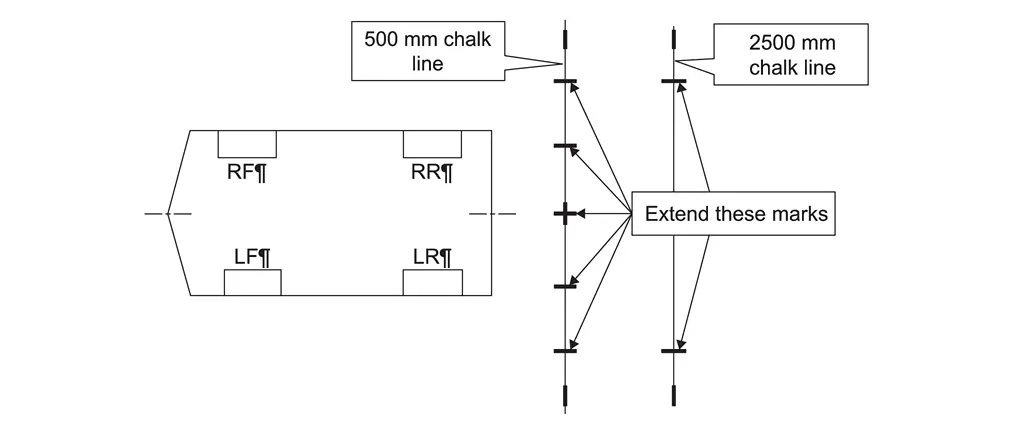
Using a carpenter's square, squared to the chalk line, extend each of the seven (7) marks 12 in. from the chalk line.
-
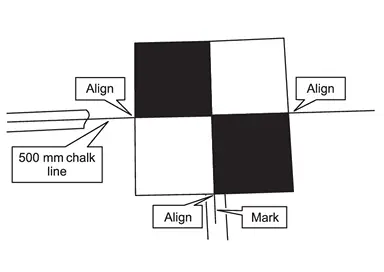
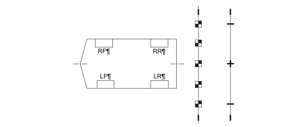
Place five (5) targets on the marks along the 500 mm (about 1.64 ft) chalk line.
NOTE:
Orient and align the targets, as shown in Figure. The targets must be aligned with the 500 mm (about 1.64 ft) chalk line and the marks made in step 10.
-
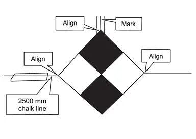
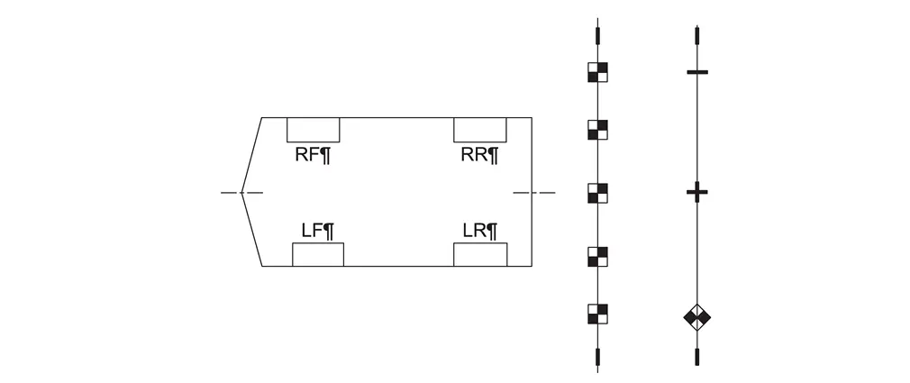
Place one (1) target on the forward most mark on the 2500 mm (about 8.2 ft) chalk line.
NOTE:
Orient and align the target, as shown in Figure. The target must be aligned with the 2500 mm (about 8.2 ft) chalk line and the mark made in step 10.
-
Place one (1) target on the rearward most mark on the 2500 mm (about 8.2 ft) chalk line.
NOTE:
Orient and align the target, as shown in Figure. The target must be aligned with the 2500 mm (about 8.2 ft) chalk line and the mark made in step 10.
-
If the passenger (RH) side camera was replaced, repeat steps 1 - 13 starting, to place the calibration targets for the passenger (RH) side camera.
>>
GO TO 4.
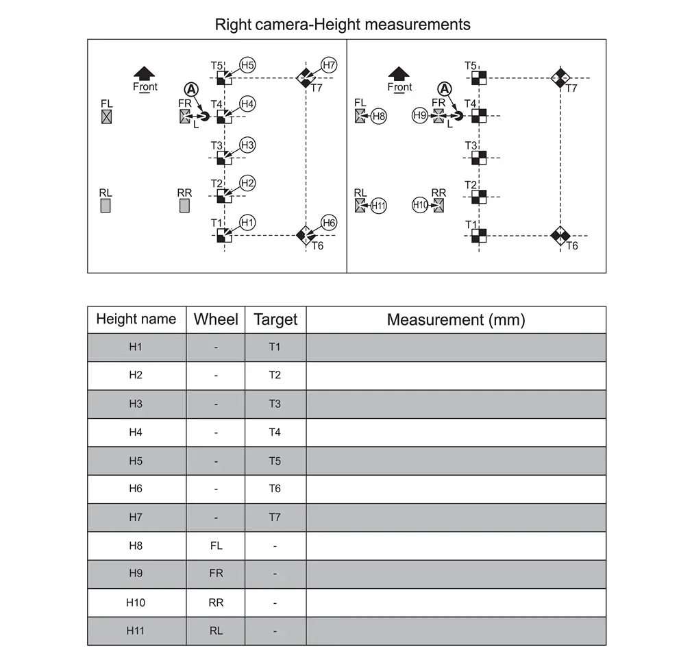
DRIVER (LH) SIDE CAMERA CALIBRATION MEASUREMENTS
-
Measure the distance between the wheel center point and the center of the calibration targets T1, T6, T7, and T5, as shown in Figure below.
NOTE:
All measurements must be in millimeters (mm). Refer to the Figure to ensure the correct measurement is documented in the correct order and for each calibration target.
-
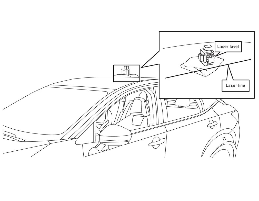
Place the laser level on a clean cloth, and then on the roof of the Nissan Ariya vehicle.
NOTE:
-
Place the laser level in the middle of the Nissan Ariya vehicleвҖҷs roof.
-
The laser level must be still (no fans should be blowing).
-
-
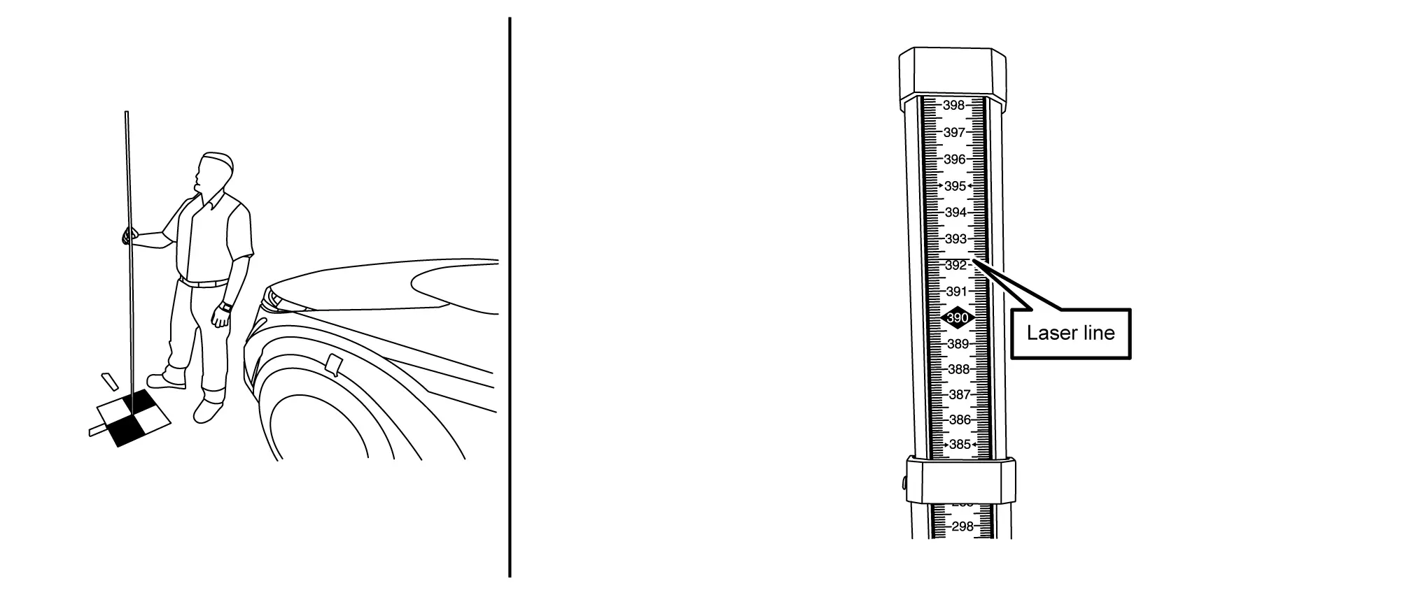
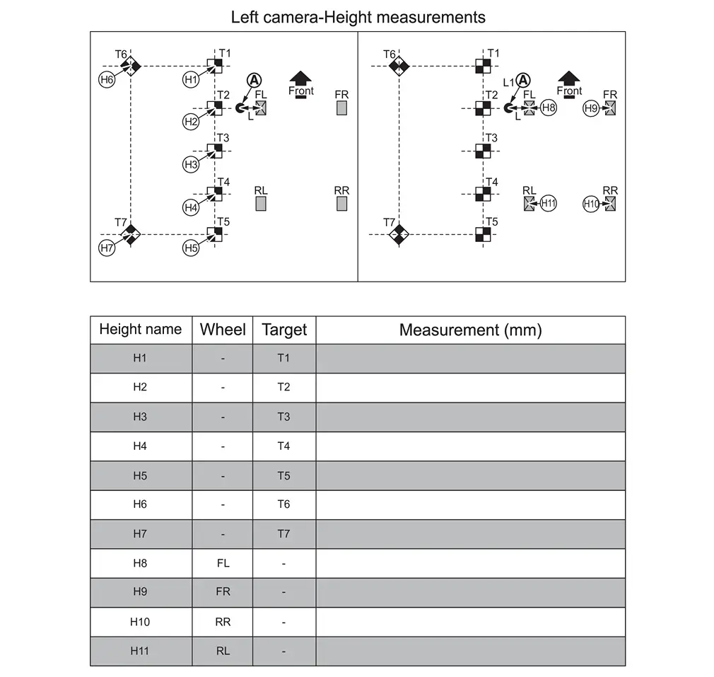
Using a leveling rod scale, measure the height from the center of each calibration target, and then record the measurements H1-H7 in the table in Figure.
NOTE:
-
When holding the leveling rod scale, ensure the ruler is completely upright and does not bend.
-
All measurements must be in millimeters (mm).
-
Refer to the table in Figure to ensure the correct measurement is documented in the correct order and for each calibration target.
-
-
Using a leveling rod scale, measure the height from the wheel center point, and then record the measurements H8-H11 in the table in Figure.
>>
GO TO 5.
PASSENGER (RH) SIDE CAMERA CALIBRATION MEASUREMENTS
-
Measure the distance between the wheel center point and the center of the calibration targets T1, T6, T7, and T5, as shown in Figure.
NOTE:
All measurements must be in millimeters (mm). Refer to the Figure to ensure the correct measurement is documented in the correct order and for each calibration target.
-
Refer to steps 2 - 4 in Procedure 4 to set up the laser level to measure the height of the passenger (RH) side camera, and then document the measurements in Figure.
NOTE:
All measurements must be in millimeters (mm). Refer to the Figure to ensure the correct measurement is documented in the correct order and for each calibration target.
>>
GO TO 6.
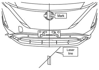
MARKING THE CENTER POINT FOR THE FRONT OF THE Nissan Ariya Vehicle
-
Place the laser level approximately 800 mm (31.5 in.) from the front of the vehicle and align the laser with the front camera, as shown in Figure.
NOTE:
Be sure to center the laser line with the front camera.
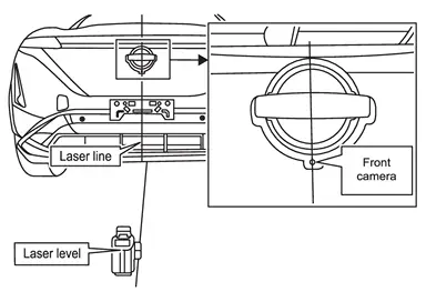
-
Mark the emblem and the floor near the front fascia.
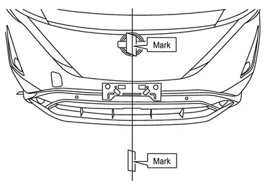
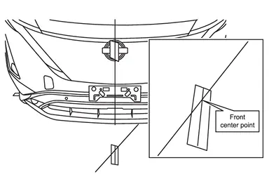
-
Move the laser so it is about 45В° and approximately 800 mm (31.5 in.) from the front of the Nissan Ariya vehicle, and then line up the vertical laser line to the mark on the emblem.
NOTE:
The laser level can be either to the left or right of the front of the Nissan Ariya vehicle.
-
Mark the floor with a cross-mark, denoting the center point of the front of the Nissan Ariya vehicle.
>>
GO TO 7.
MARKING THE CENTER POINT FOR THE REAR OF THE Nissan Ariya Vehicle
-
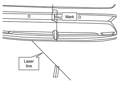
Place the laser level approximately 800 mm (31.5 in.) from the rear of the vehicle and align the laser with the center mark at the front of the Nissan Ariya vehicle and the circle in between the Ss in NISSAN, as shown in Figure.
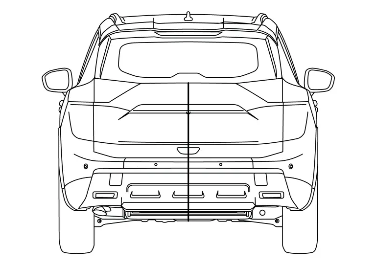
-
Mark the rear fascia, where shown in Figure, and the floor near the rear fascia.
-
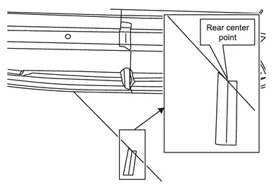
Move the laser so it is about 45В° and approximately 800 mm (31.5 in.) from the rear of the Nissan Ariya vehicle, and then line up the vertical laser line to the mark on the rear fascia.
NOTE:
The laser level can be either to the left or right of the front of the Nissan Ariya vehicle.
-
Mark the floor with a cross-mark, denoting the center point of the rear of the Nissan Ariya vehicle.
>>
GO TO 8.
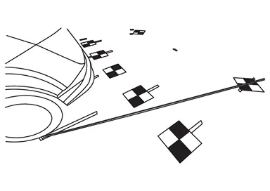
PLACING CALIBRATION TARGETS FOR THE FRONT AND/OR REAR CAMERAS
NOTE:
Steps 1 - 15 and the related figures show the rear of the Nissan Ariya vehicle. The front is similar. If the AVM Control Module was replaced, steps 1 - 15 must be performed for both the front and rear cameras.
-
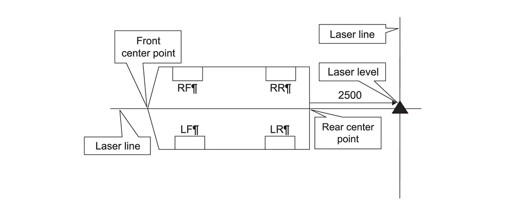
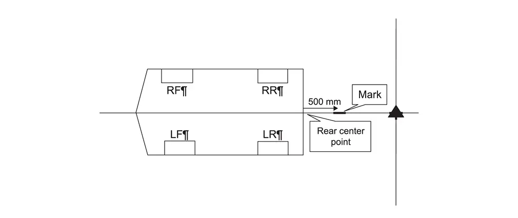
Place the laser level 2500 mm (about 8.2 ft) from the rear center point of the Nissan Ariya vehicle, and then align the laser line with both the front and rear center points, as shown in Figure.
-
Place a cross-mark on the floor below the laser line.
-
Measure and place a mark 500 mm (about 1.64 ft) from the rear center point.
-
Measure and place a mark 2500 mm (about 8.2 ft) to the left and to the right of the laser level, as shown in Figure.
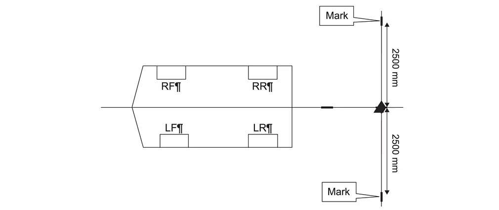
-
Move the laser to the 500 mm (about 1.64 ft) mark, and then measure and place a mark 2500 mm (about 8.2 ft) to the left and to the right of the laser level, as shown in Figure.
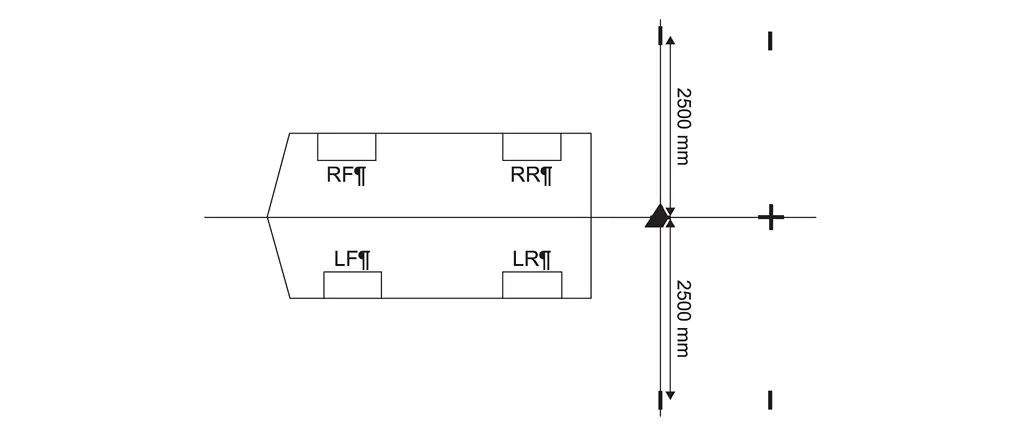
-
Use a chalk line tool to make a line between the 500 mm (about 1.64 ft) and 2500 mm (about 8.2 ft) marks, as shown in Figure.
-
Place the laser level with both vertical lines activated and align one laser line with the 500 mm (about 1.64 ft) chalk line and align the other laser line to the front and rear center point of the Nissan Ariya vehicle, as shown in Figure.
NOTE:
The laser line must be perfectly aligned with the 500 mm (about 1.64 ft) chalk line and the front and rear center points.
-
Place a cross-mark on the floor below the laser line.
-
Measure and mark 1000 mm (about 3.28 ft) increments, as shown in Figure.
-
Move the laser level to the position shown in Figure, and then make a mark on the 2500 mm (about 8.2 ft) chalk line, as shown in Figure.
NOTE:
The laser line must be perfectly aligned with the 500 mm (about 1.64 ft) chalk line.
-
Move the laser level to the position shown in Figure, and then make a mark on the 2500 mm (about 8.2 ft) chalk line, as shown in Figure.
NOTE:
The laser line must be perfectly aligned with the 500 mm (about 1.64 ft) chalk line.
-
Using a carpenter's square, squared to the chalk line, extend each of the seven (7) marks 12 in. from the chalk line.
-
Place five (5) targets on the marks along the 500 mm (about 1.64 ft) chalk line.
NOTE:
Orient and align the targets, as shown in figure. The targets must be aligned with the 500 mm (about 1.64 ft) chalk line and the marks made in step 12.
-
Place one (1) target on the driver (LH) side mark on the 2500 mm (about 8.2 ft) chalk line.
NOTE:
Orient and align the target, as shown in Figure. The target must be aligned with the 2500 mm (about 8.2 ft) chalk line and the marks made in step 12.
-
Place one (1) target on the driver (RH) side mark on the 2500 mm (about 8.2 ft) chalk line.
NOTE:
Orient and align the target, as shown in Figure. The target must be aligned with the 2500 mm (about 8.2 ft) chalk line and the marks made in step 12.
-
If the front camera was replaced, repeat steps 1 - 15 starting, to place the calibration targets for the front camera.
-
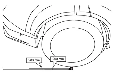
Measure 200 mm (about 7.87 in) and 283 mm (about 11.14 in) from the center point of the driver (LH) side rear wheel, and then make a mark at each measurement, as shown in Figure.
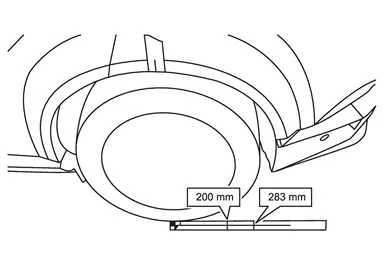
-
Measure 200 mm (about 7.87 in) and 283 mm (about 11.14 in) from the center point of the passenger (RH) side rear wheel, and then make a mark at each measurement, as shown in Figure.
>>
GO TO 9.
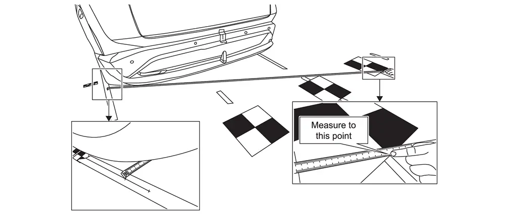
REAR CAMERA CALIBRATION MEASUREMENTS
-
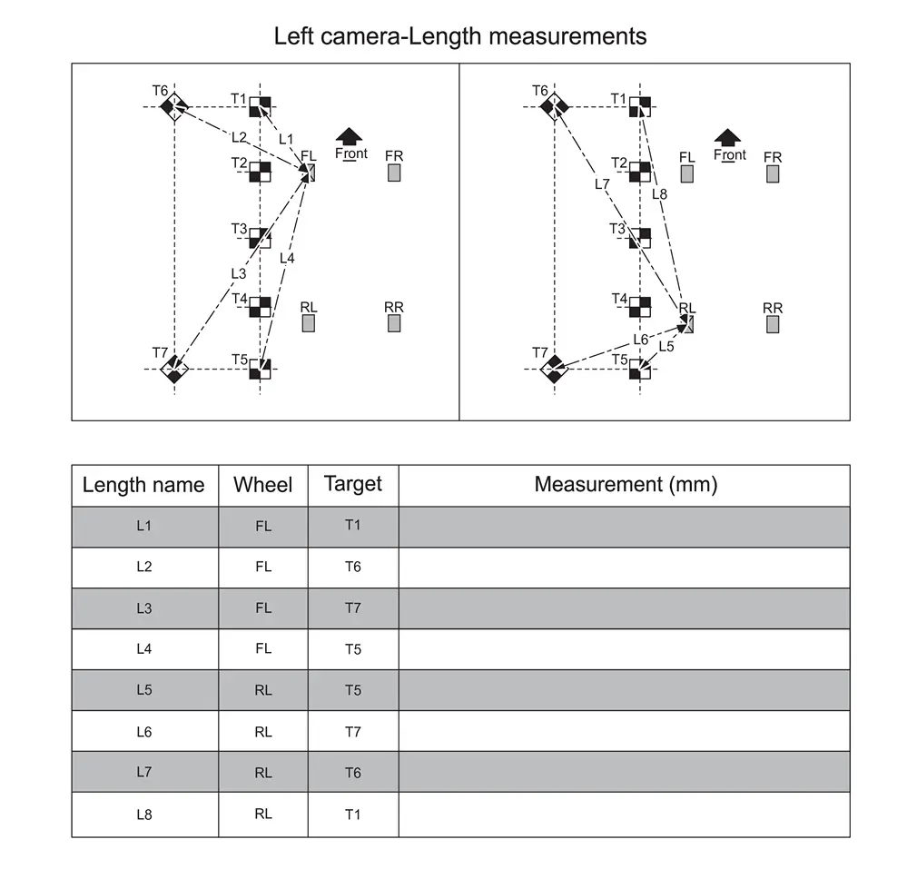
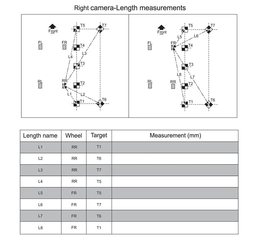
Measure the distance between the center point of the driver (LH) side rear wheel to the center of the calibration target T1, and then document that distance as L1.
-
Measure the distance between the center point of the driver (LH) side rear wheel to the center of the calibration target T6, and then document that distance as L2.
-
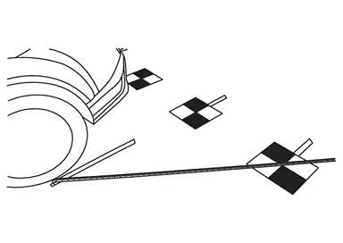
Measure the distance between the 283 mm (about 11.14 in) mark of the driver (LH) side rear wheel to the most rearward point of the calibration target T7, and then document that distance as L3.
NOTE:
Do not measure to the center point of the target. Measure to the point shown in Figure.
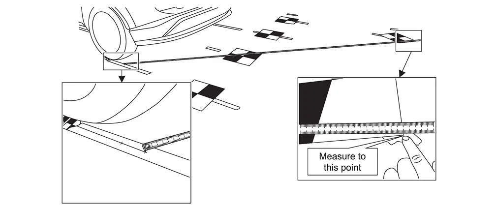
-
Measure the distance between the 200 mm (about 7.87 in) mark of the driver (LH) side rear wheel to the most rearward point of the calibration target T5, and then document that distance as L4.
NOTE:
Do not measure to the center point of the target. Measure to the point shown in Figure.
-
Perform steps 1 - 4 starting for the passenger (RH) side rear wheel measurements L5-L8, and then document the distances in Figure.
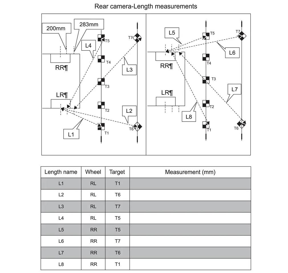 NOTE:
NOTE:
L3, L4, L7 and L8 are not to center of target.
-
Place the laser level on a clean cloth, and then on the roof of the Nissan Ariya vehicle.
NOTE:
-
Place the laser level in the middle of the Nissan Ariya vehicleвҖҷs roof.
-
The laser level must be still (no fans should be blowing).
-
-
Using a folding carpenterвҖҷs ruler, measure the height from the center of each calibration target, and then record the measurements H1-H7 in the table in Figure.
NOTE:
-
When holding the carpenterвҖҷs wooden folding ruler (carpenterвҖҷs ruler), ensure the ruler is completely upright and does not bend.
-
All measurements must be in millimeters (mm).
-
Refer to the table in Figure to ensure the correct measurement is documented in the correct order and for each calibration target.
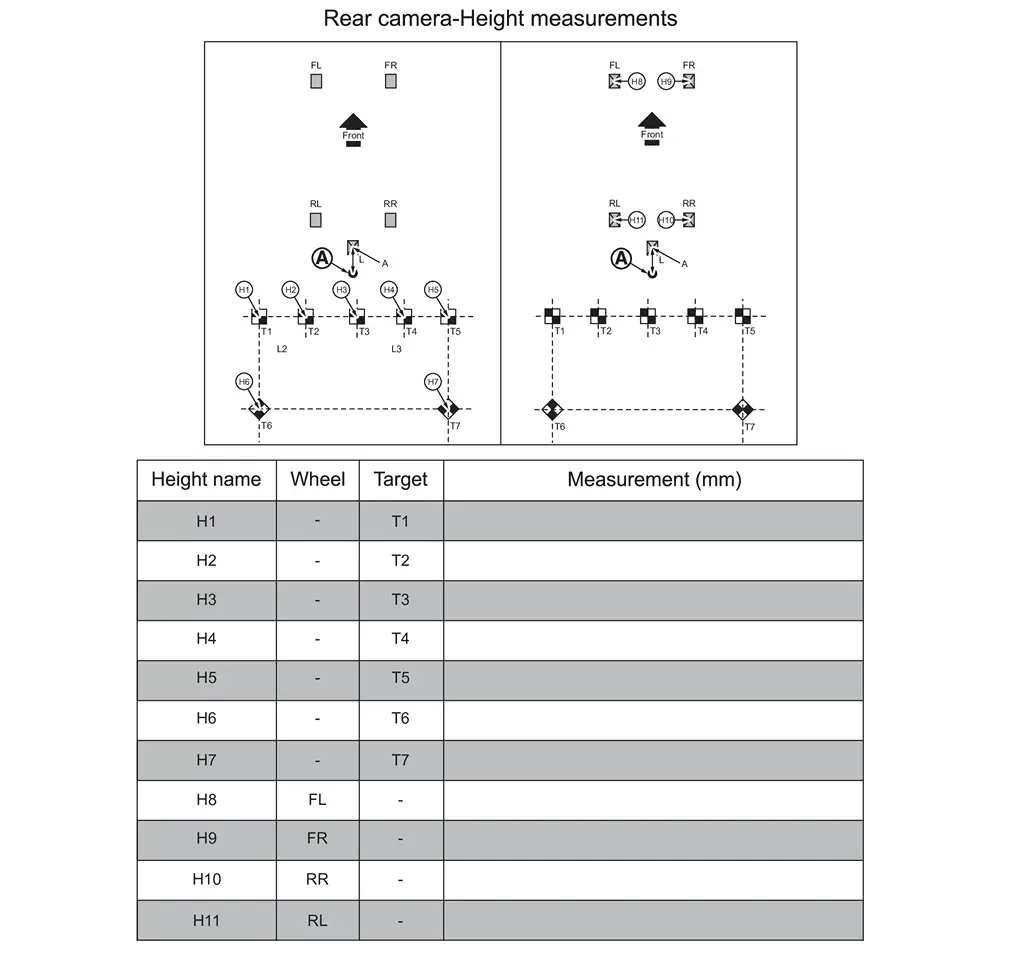
-
-
Using a folding carpenterвҖҷs ruler, measure the height from the wheel center point, and then record the measurements H8-H11 in the table in Figure.
>>
GO TO 10.
FRONT CAMERA CALIBRATION MEASUREMENTS
NOTE:
IMPORTANT: All measurements must be in millimeters (mm). Refer to the Figure to ensure the correct measurement is documented in the correct order and for each calibration target.
-
Perform steps 17 in Procedure 8 to step 5 in Procedure 9 starting for the front camera.
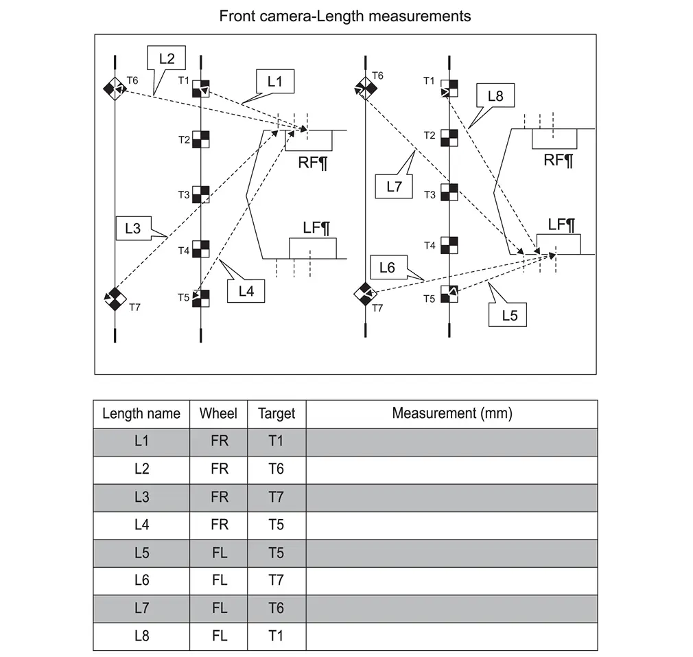 NOTE:
NOTE:
L3, L4, L7 and L8 are not to center of target.
-
Refer to steps 6 - 8 in Procedure 9 to set up the laser level to measure the height of the front camera, and then document the measurements in Figure.
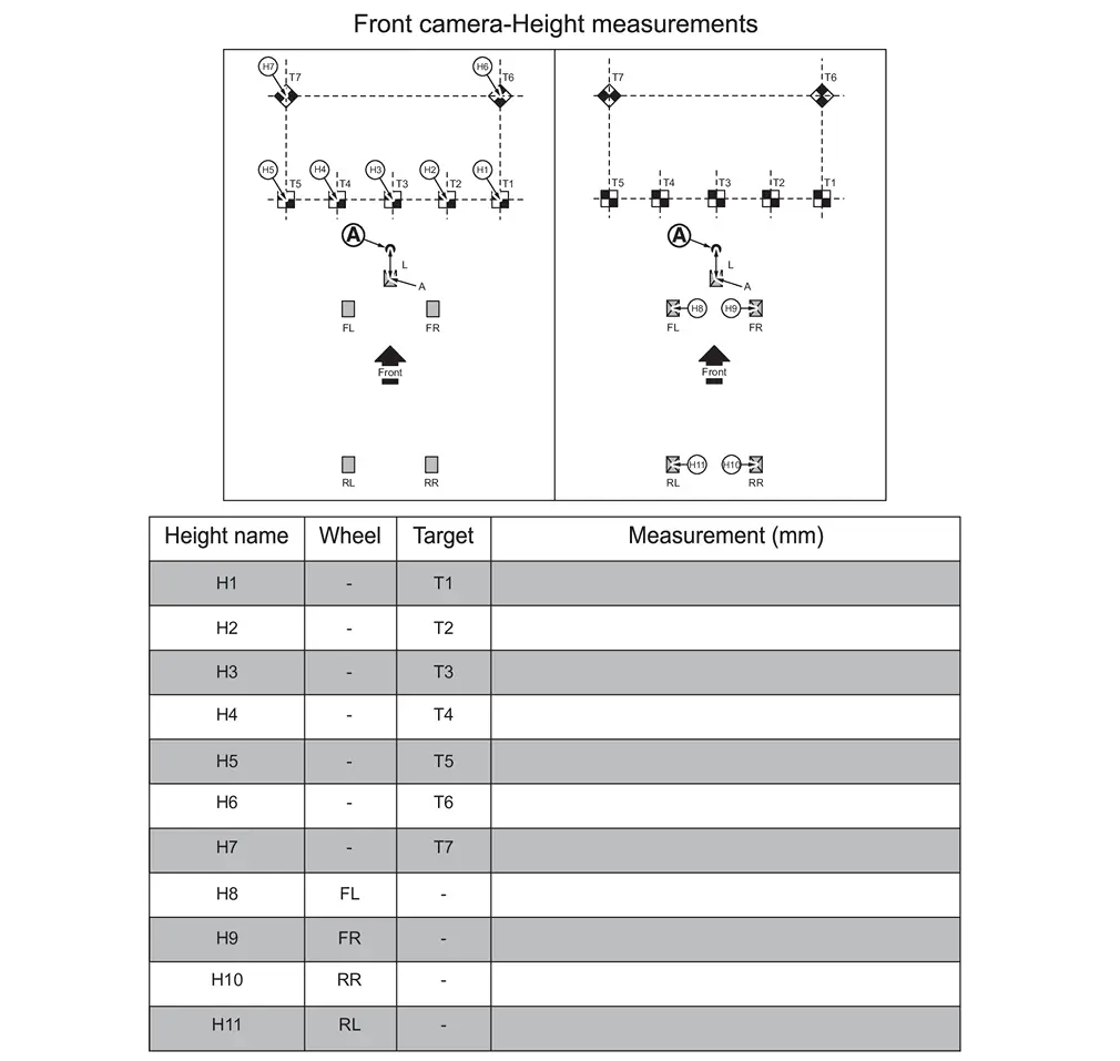
>>
GO TO 11.
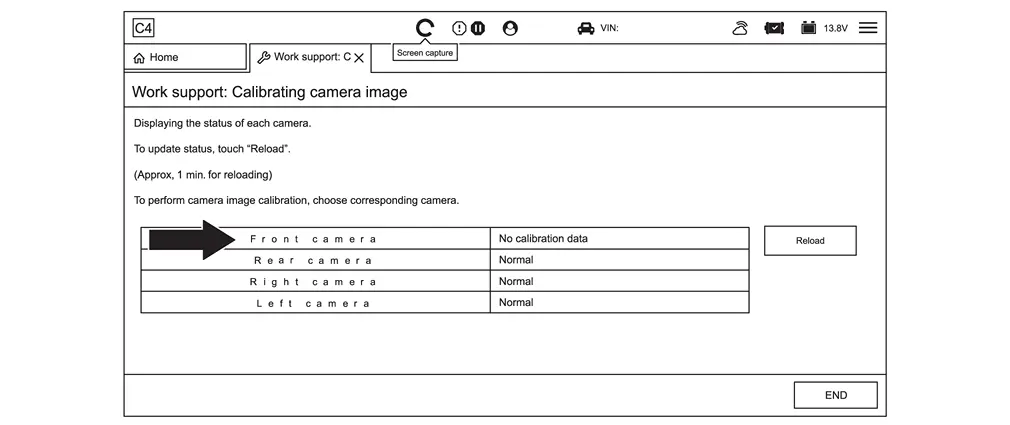
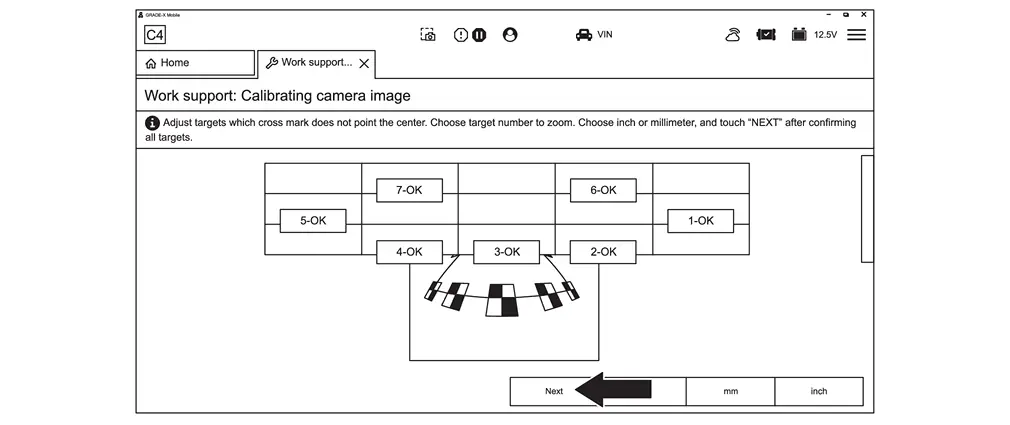
INPUT THE CALIBRATION TARGET MEASUREMENTS IN CONSULT
-
Select Calibrating camera image, and then select the green Play icon.
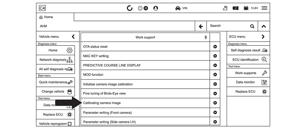
-
Select the camera that needs to be calibrated.
NOTE:
вҖңNo calibration dataвҖқ displays next to the camera that needs to be calibrated.
-
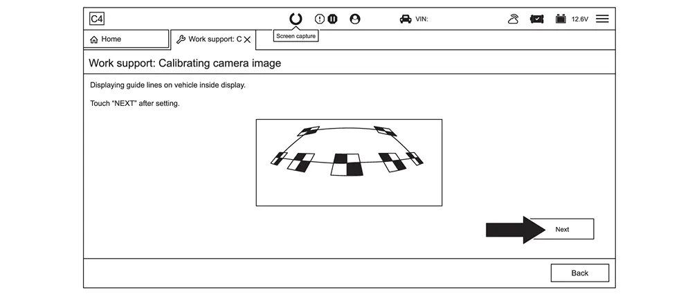
Select Next.
-
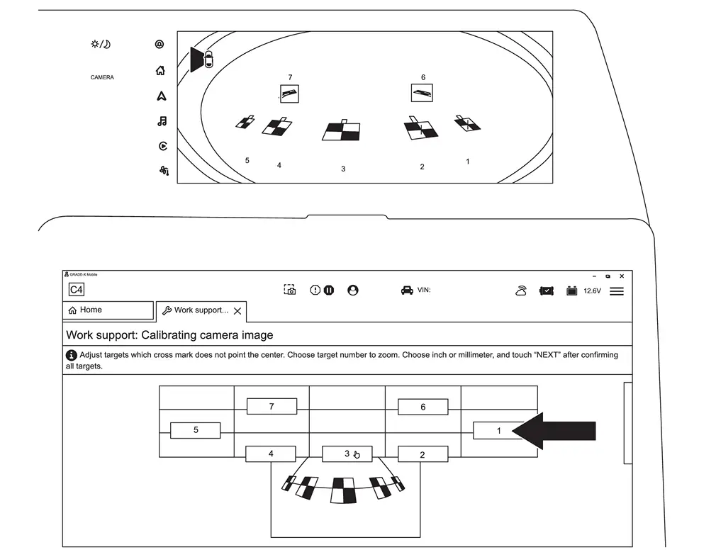
Select 1.
NOTE:
Steps 4 - 15 must be done at once. Do not stop in the middle of performing these steps as CONSULT 4 will time out and all progress will be lost.
-
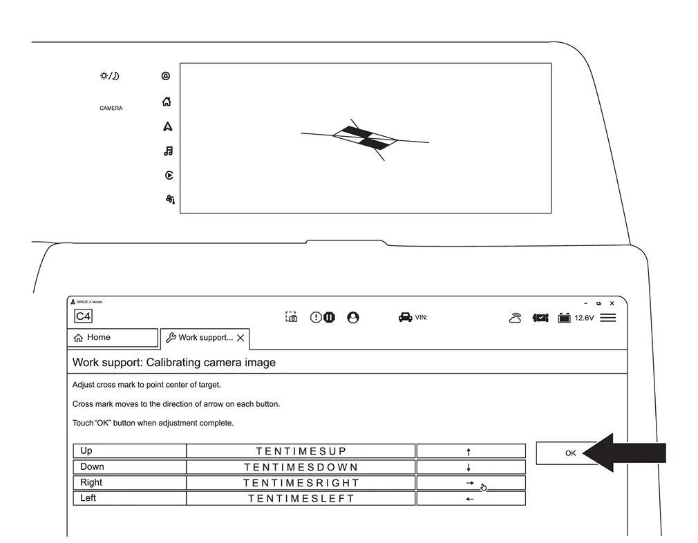
Move the center of the red crosshair to the center of the calibration target.
NOTE:
The TENTIMESUP, TENTIMESDOWN, TENTIMESRIGHT, and TENTIMESLEFT boxes will make large adjustments. The arrows will make small adjustments.
-
When the center of the red crosshair is in the center of the calibration target, select OK.
-
Repeat steps 4 - 6 starting on page 58, for all seven (7) targets, and then select mm.

-
Select Next.
-
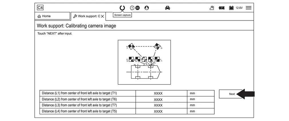
Input the length measurements L1-L4 documented for the camera being calibrated, and then select Next.
-
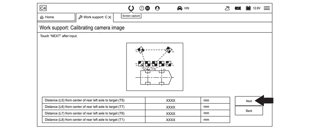
Input the length measurements L5-L8 documented for the camera being calibrated, and then select Next.
-
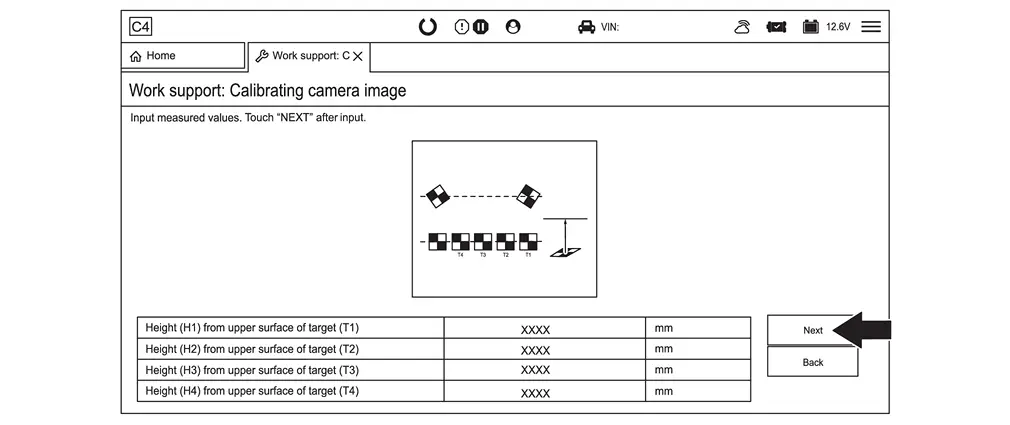
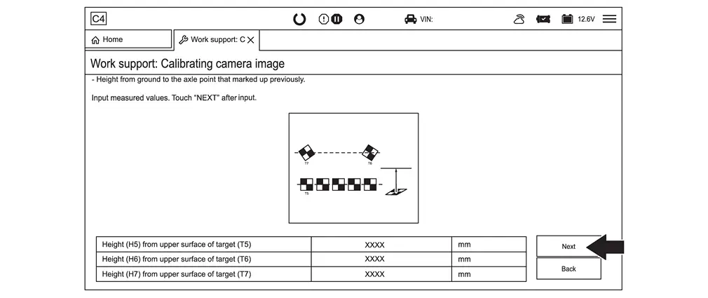
Input the height measurements H1-H4 documented for the camera being calibrated, and then select Next.
-
Input the height measurements H5-H7 documented for the camera being calibrated, and then select Next.
-
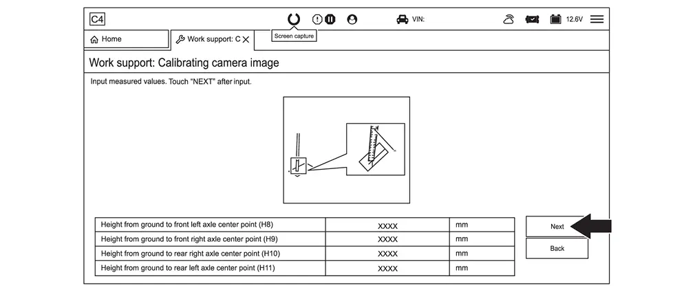
Input the height measurements H8-H11 documented for the camera being calibrated, and then select Next.
-
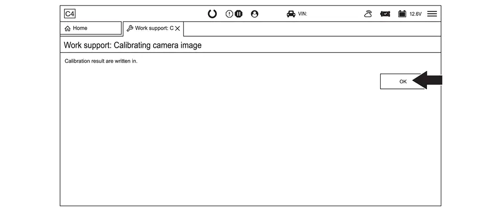
Select OK.
-
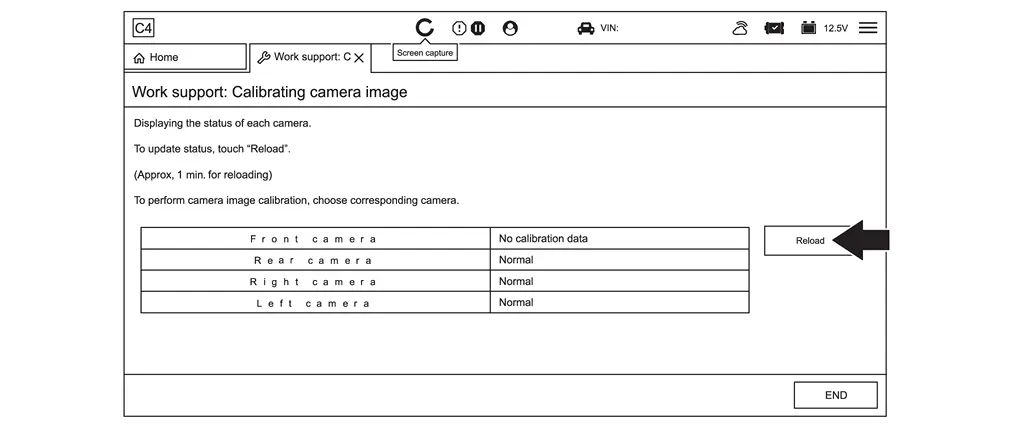
Select Reload.
NOTE:
The camera will show вҖңNo calibration dataвҖқ until the Reload box is selected.
-
Perform steps 2 - 15 starting, for all cameras that require calibration.
-
Select END.
-
Clear all DTCs.
-
Remove the laser level from the top of the Nissan Ariya vehicle.
-
Remove all tape and markings from the vehicle.
-
Ensure all around view monitor cameras are working properly and all DTCs have been cleared.
>>
Work End.
Other materials:
B2600-42 Configuration Error
DTC Description
DTC DETECTION LOGIC DTC No. CONSULT screen terms DTC detected condition
B2600-42
Configuration error
Diagnosis condition
After the ignition switch OFF, wait for 1 minutes or more
When ignition switch is ON.
Signal (terminal)
вҖ”
Threshold
...
Comment utiliser le HUD (Affichage TГӘte Haute) de votre Nissan Rogue
Informations de base et activation
LвҖҷutilisation du systГЁme dвҖҷaffichage tГӘte haute (HUD) sur le Nissan Rogue est conГ§ue pour ГӘtre aussi simple qu'efficace. Pour activer cette technologie de projection laser, il vous suffit d'appuyer sur la commande dГ©diГ©e "HUD" situГ©e sur le pannea ...
P00fe Evap Control System
DTC Description
This diagnosis detects clogs in the EVAP line between fuel tank and EVAP canister purge volume control solenoid valve.ECM
controls EVAP control system as below. ECM monitors EVAP line pressure
change to diagnose if there is no clogging between EVAP canister and
fuel tank.
E ...