Nissan Rogue (T33) 2021-Present Service Manual: B24f4-14 Heated Steering Wheel Relay
DTC Description
DTC DETECTION LOGIC
| DTC No. |
CONSULT screen terms (Trouble diagnosis content) | DTC detection condition | |
|---|---|---|---|
| B24F4-14 |
Heated steering wheel relay (Heated steering wheel relay) |
Diagnosis condition | Ignition switch ON |
| Signal (Terminal) | Heated steering wheel relay control circuit | ||
| Threshold | Open or short to ground | ||
| Diagnosis delay time | — | ||
POSSIBLE CAUSE
-
Heated steering wheel relay
-
A/C amp.
-
Harness or connectors (heated steering wheel relay control circuit is open or shorted to ground)
FAIL-SAFE
—
DTC CONFIRMATION PROCEDURE
PERFORM DTC CONFIRMATION PROCEDURE
 CONSULT
-
Ignition switch ON.
-
Select “Self diagnosis result” mode of “HVAC”.
-
Check DTC.
Is DTC detected?
YES>>Refer to Diagnosis Procedure.
NO-1>>To check malfunction symptom before repair: Refer to Intermittent Incident.
NO-2>>Confirmation after repair: Inspection End.
DTC Diagnosis Procedure
CHECK FUSE
-
Ignition switch OFF.
-
Check that the following fuse is not blown (open).
| Unit | Location | Fuse No. | Capacity |
|---|---|---|---|
| Heated steering wheel relay | Fuse block (J/B) | #40 | 10 A |
Is the fuse blown (open)?
YES>>Replace the blown (open) fuse after repairing the affected circuit if a fuse is blown (open).
NO>>GO TO 2.
CHECK HEATED STEERING WHEEL RELAY CONTROL SIGNAL CIRCUIT
-
Disconnect A/C amp. connector.
-
Ignition switch ON.
-
Check voltage between A/C amp. harness connector and ground.
(+) (‚àí) Voltage A/C amp. Connector Terminal M55 56 Ground Battery voltage
Is the inspection result normal?
YES>>Replace A/C amp. Refer to Removal and Installation.
NO>>GO TO 3.
CHECK HEATED STEERING WHEEL RELAY POWER SUPPLY CIRCUIT FOR OPEN
-
Ignition switch OFF.
-
Remove heated steering wheel relay and disconnect fuse block (J/B) connector.
-
Check continuity between heated steering wheel relay harness connector and fuse block (J/B) harness connector.
Heated steering wheel relay Fuse block (J/B) Continuity Connector Terminal Connector Terminal M95 1 M68 12F Yes
Is the inspection result normal?
YES>>GO TO 4.
NO>>Repair harness or connector.
CHECK HEATED STEERING WHEEL RELAY CONTROL SIGNAL CIRCUIT FOR OPEN
Check continuity between heated steering wheel relay harness connector and A/C amp. harness connector.
| Heated steering wheel relay | A/C amp. | Continuity | ||
|---|---|---|---|---|
| Connector | Terminal | Connector | Terminal | |
| M95 | 2 | M55 | 56 | Yes |
Is the inspection result normal?
YES>>GO TO 5.
NO>>Repair harness or connector.
CHECK HEATED STEERING WHEEL RELAY CONTROL SIGNAL CIRCUIT FOR SHORT
Check continuity between A/C amp. harness connector and ground.
| A/C amp. | (—) | Continuity | |
|---|---|---|---|
| Connector | Terminal | ||
| M55 | 56 | Ground | No |
Is the inspection result normal?
YES>>GO TO 6.
NO>>Repair harness or connector.
CHECK HEATED STEERING WHEEL RELAY
Check heated steering wheel relay. Refer to Component Inspection.
Is the inspection result normal?
YES>>Inspection End.
NO>>Replace heated steering wheel relay.
Component Inspection
CHECK HEATED STEERING WHEEL RELAY
-
Ignition switch OFF.
-
Remove heated steering wheel relay.
-
Check continuity between heated steering wheel relay terminal 3 and 5 when the voltage is supplied between terminal 1 and 2.
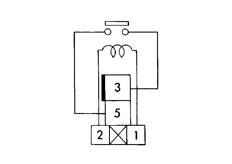
Terminal Condition Continuity 3 5 Battery voltage Apply Yes Not apply No
Is the inspection result normal?
YES>>Inspection End.
NO>>Replace heated steering wheel relay.
Other materials:
Ecu Diagnosis Information. Intelligent Key Unit
Reference Value
VALUES ON THE DIAGNOSIS TOOLNOTE:
The following table includes information (items)
inapplicable to this Nissan Ariya vehicle. For information (items)
applicable to this vehicle, refer to CONSULT display items.
CONSULT MONITOR ITEM Monitor Item Condition Value/Status
Intel ...
Cooling Fan
Component Function Check
CHECK COOLING FAN FUNCTION
With CONSULT
Turn ignition switch ON.
Perform “FAN DUTY CONTROL” in “ACTIVE TEST” mode of “ECM” using CONSULT.
Touch “LOW”, “HI” on the CONSULT screen.
Check that cooling fan operates.
Is the inspectio ...
P2480 Exhaust Gas Temperature Sensor
DTC Description
DTC DETECTION LOGIC DTC
CONSULT screen terms
(Trouble diagnosis content)
DTC detection condition
P2480
00
Exhaust gas temp sensor bank 1
(Exhaust Gas Temperature sensor Circuit/Open Bank 1 Sensor 5)
Diagnosis condition
Ignition switch ON
Signal
— ...