Nissan Rogue (T33) 2021-Present Service Manual: Active Noise Control Unit
Reference Value
VALUES ON THE DIAGNOSIS TOOL
| Monitor Item | Condition | Value/Status | |
|---|---|---|---|
| Active sound control operating condition | Active sound control system is not operating. | Off | |
| Active sound control system is operating. | On | ||
| Active noise control operating condition | Active noise cancellation system is not operating. | Off | |
| Active noise cancellation system is operating. | On | ||
| Engine speed | Engine running | Almost the same speed as the tachometer indication | |
| Nissan Ariya VehicleSpeed 1 | During vehicle driving | Input value of Nissan Ariya vehicle speed signal | |
TERMINAL LAYOUT
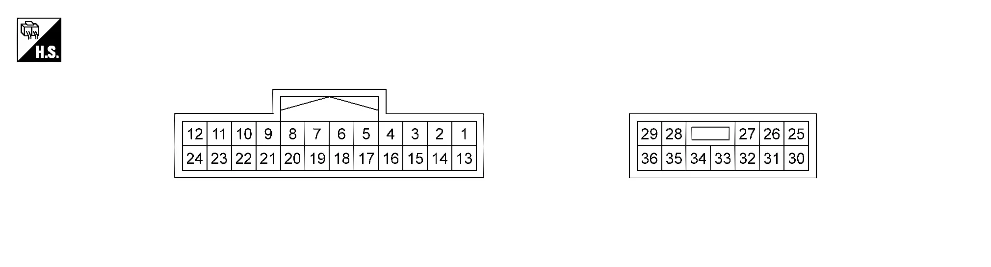
PHYSICAL VALUES
|
Terminal (Wire color) | Description | Condition | Standard |
Reference value (Approx.) | ||
|---|---|---|---|---|---|---|
| + | ŌĆō | Signal name | Input/Output | |||
|
1 (W)1 (P)2 |
13 (Y) |
Active noise control microphone LH signal | Input |
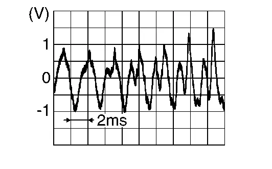
[Ignition switch ON] Sound input |
Inputs waveform synchronized with sound |
|
|
2 (P) |
14 (BG)3 (G)4 |
Active noise control microphone RH signal | Input |
[Ignition switch ON] Sound input |
Inputs waveform synchronized with sound |
|
|
3 (BR) |
15 (L) |
Active noise control microphone rear signal | Input |
[Ignition switch ON] Sound input |
Inputs waveform synchronized with sound |
|
|
6 (Y)3 (V)4 |
Ground | Engine speed signal | Input | Idle speed | ŌĆö |
|
|
7 (L) |
ŌĆö | CAN-High | Input/ Output | ŌĆö | ŌĆö | ŌĆö |
|
9 (G) |
21 (R) |
Sound signal front LH | Input |
[Ignition switch ON] Sound signal output |
Inputs waveform synchronized with sound. |
|
|
10 (R) |
22 (L) |
Sound signal front RH | Input |
[Ignition switch ON] Sound signal output |
Inputs waveform synchronized with sound. |
|
|
19 (R) |
ŌĆö | CAN-Low | Input/ Output | ŌĆö | ŌĆö | ŌĆö |
|
25 (B) |
Ground | Ground | ŌĆö | [Ignition switch ON] | ŌĆö | 0 V |
|
26 (GR)3, 5 (V)6 |
31 (SB)3, 5 (W)6 |
Sound signal front LH output | Output |
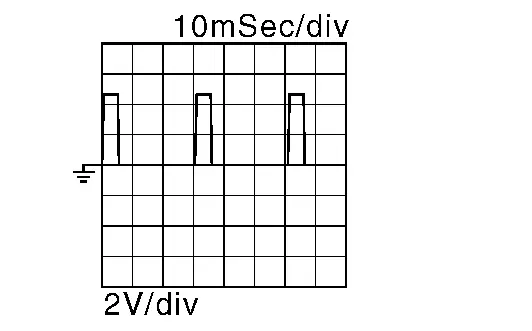
[Ignition switch ON] Sound signal output |
Outputs waveform synchronized with sound. |
|
|
27 (P)3, 5 (G)6 |
32 (W) |
Sound signal front RH output | Output |
[Ignition switch ON] Sound signal output |
Outputs waveform synchronized with sound. |
|
|
28 (LG) |
35 (L) |
Sound signal subwoofer 2 | Output |
[Ignition switch ON] Sound signal output |
Outputs waveform synchronized with sound. |
|
|
29 (SB) |
25 (B) |
Battery power supply | Input | [Ignition switch OFF] | 10.8 ŌĆō 15.6 V | Battery voltage |
|
30 (B) |
Ground | Ground | ŌĆö | [Ignition switch ON] | ŌĆö | ŌĆö |
|
33 (R) |
34 (BG) |
Sound signal subwoofer 1 | Output |
[Ignition switch ON] Sound signal output |
Outputs waveform synchronized with sound. |
|
|
36 (SB)3 (GR)4 |
25 (B) |
Battery power supply | Input | [Ignition switch OFF] | 10.8 ŌĆō 15.6 V | Battery voltage |
1: With ProPILOT Assist 2.1
2: Without ProPILOT Assist 2.1
3: USA production
4: Japan production
5: Japan production with ProPILOT Assist 2.1
6: Japan production without ProPILOT Assist 2.1
Fail-Safe
If a malfunction occurs in the active noise cancellation or active sound enhancement, active noise control unit performs fail-safe activation according to the detected malfunction.
| DTC | Fail-safe mode | |
|---|---|---|
| B1A01 | 11/12/13/1A | Audio output is stopped. |
| B1A05 | 11/12/13/1A | |
| B1A0A | 13 | |
| B1A12 | 13 | |
| B1A69 | 11/12/13/1A | |
| B1A71 | 11/12/13/1A | |
| B1F00 | 49 | Amplifier function is stopped |
| B1F01 | 62 | Active noise cancellation and active sound enhancement are deactivated |
| B1F05 | 29 | |
| B1F21 | 29 | |
| B1F26 | 29 | Active noise cancellation and active sound enhancement are fixed to a standard mode. |
| B1F06 | 29 | Active sound enhancement function is deactivated |
| B1F07 | 29 | |
| B1F20 | 29 | |
| B1F24 | 29 | |
| B1F0A | 16 | Active noise cancellation function is deactivated |
| B1F0B | 13 | |
| B1F0C | 2B | |
| B1F0F | 16 | |
| B1F10 | 13 | |
| B1F11 | 2B | |
| B1F14 | 16 | |
| B1F15 | 13 | |
| B1F16 | 2B | |
| U2140 | 87 | The system using the CAN communication signal from control unit which cannot communicate does not function. |
| U2141 | 87 | |
| U2148 | 87 | |
| U214E | 87 | |
| U214F | 87 | |
| U2154 | 87 | |
| U2176 | 87 | |
DTC Inspection Priority Chart
If multiple DTCs are detected simultaneously, check them one by one depending on the following DTC inspection priority chart.
| Priority | Detected items (DTC) |
|---|---|
| 1 |
|
| 2 |
|
| 3 |
|
DTC Index
Self Diagnostic Result
| DTC | Display item | Refer to |
|---|---|---|
| B1A01-11 | FL-DOOR woofer OUT | DTC Description |
| B1A01-12 | FL-DOOR woofer OUT | DTC Description |
| B1A01-13 | FL-DOOR woofer OUT | DTC Description |
| B1A01-1A | FL-DOOR woofer OUT | DTC Description |
| B1A05-11 | FR-DOOR woofer OUT | DTC Description |
| B1A05-12 | FR-DOOR woofer OUT | DTC Description |
| B1A05-13 | FR-DOOR woofer OUT | DTC Description |
| B1A05-1A | FR-DOOR woofer OUT | DTC Description |
| B1A0A-13 | Front instrument left squawker out | DTC Description |
| B1A12-13 | Front instrument right squawker out | DTC Description |
| B1A69-11 | Rear luggage left woofer out | DTC Description |
| B1A69-12 | Rear luggage left woofer out | DTC Description |
| B1A69-13 | Rear luggage left woofer out | DTC Description |
| B1A69-1A | Rear luggage left woofer out | DTC Description |
| B1A71-11 | Rear luggage right woofer out | DTC Description |
| B1A71-12 | Rear luggage right woofer out | DTC Description |
| B1A71-13 | Rear luggage right woofer out | DTC Description |
| B1A71-1A | Rear luggage right woofer out | DTC Description |
| B1F00-49 | ANC UNIT | DTC Description |
| B1F01-62 | ENG SPEED SIG ERROR | DTC Description |
| B1F05-29 | CAN SIG ERROR/DIAG | DTC Description |
| B1F06-29 | CAN SIG ERROR/ASC | DTC Description |
| B1F07-29 | CAN signal error/Mode switching | DTC Description |
| B1F0A-16 | ANC MIC1/CONTROL UNIT | DTC Description |
| B1F0B-13 | ANC MIC 1 INPUT | DTC Description |
| B1F0C-2B | ANC MIC1 | DTC Description |
| B1F0F-16 | ANC MIC2/CONTROL UNIT | DTC Description |
| B1F10-13 | ANC MIC 2 INPUT | DTC Description |
| B1F11-2B | ANC MIC2 | DTC Description |
| B1F14-16 | ANC MIC3/CONTROL UNIT | DTC Description |
| B1F15-13 | ANC MIC 3 INPUT | DTC Description |
| B1F16-2B | ANC MIC3 | DTC Description |
| B1F20-29 | CAN signal error/ASE | DTC Description |
| B1F21-29 | CAN signal error/ANC | DTC Description |
| B1F24-29 | CAN SIG ERROR/ASC | DTC Description |
| B1F26-29 | CAN signal error (TCU) | DTC Description |
Network-DTC
| U2140ŌĆō87 | CAN comm err (ECM) | DTC Description |
| U2141ŌĆō87 | CAN comm err (TCM) | DTC Description |
| U2148ŌĆō87 | CAN comm err (brake control unit) | DTC Description |
| U214EŌĆō87 | CAN comm err (combination meter) | DTC Description |
| U214FŌĆō87 | CAN comm err (BCM) | DTC Description |
| U2154ŌĆō87 | CAN comm err (MIU) | DTC Description |
| U2176ŌĆō87 | CAN comm err (CCM) | DTC Description |
Other materials:
Steering Switch Signal a Circuit
Component Function Check
CHECK COMBINATION METER INPUT SIGNAL
CONSULT
Ignition switch ON.
Select ŌĆ£Steering switch inputŌĆØ in ŌĆ£Data monitorŌĆØ mode of ŌĆ£M&AŌĆØ.
Check that the function operates normally according to the following conditions:
Condition Value
CONTRO ...
P11b0 Vcr Target Angle (cold Start)
DTC Description
DTC DETECTION LOGIC DTC
CONSULT screen terms
(Trouble diagnosis content)
DTC detection condition
P11B0
00
VCR target angle (cold start)
[Variable compression ratio target angle (cold start)]
Diagnosis condition
Engine cold start
Signal (terminal)
Ō ...
P055f Engine Oil Pressure
DTC Description
DTC DETECTION LOGIC DTC
CONSULT screen terms
(Trouble diagnosis content)
DTC detection condition
P055F
Engine oil pressure
(Engine oil pressure out of range)
Diagnosis condition
After ECM self shut-off.
Engine oil temperature is more than -10 Ōäā(14 ...