Nissan Rogue (T33) 2021-Present Service Manual: Av Control Unit
Nissanconnect with 8" Color Display
Reference Value
VALUES ON THE DIAGNOSIS TOOL
 NOTE:
NOTE:
The following table includes information (items) inapplicable to this Nissan Ariya vehicle. For information (items) applicable to this vehicle, refer to CONSULT display items.
| Monitor Item | Condition | Value/Status | |
|---|---|---|---|
| Auto ACC |
It depends on Nissan Ariya vehicle architecture. |
On/Off | |
| ACC | Ignition switch ACC | On | |
| Ignition switch OFF | Off | ||
| Aux IN 1 | Ignition switch ON | Accessory connected to USB. | Connnected |
| Accessory not connected to USB. | Not connected | ||
| Parking brake | Ignition switch ON | Parking brake applied. | On |
| Parking brake not applied. | Off | ||
| TCU mute signal | Ignition switch ON | TCU sending mute signal. | On |
| TCU not sending mute signal. | Off | ||
| REVERSE SIGNAL | Ignition switch ON | Selector lever in R position. | On |
| Selector lever in any position other than R. | Off | ||
| ILLUMINATION SIGNAL | Ignition switch ON | Illumination signal received. | On |
| Illumination signal not received. | Off | ||
| Sunload sensor | Ignition switch ON | On | |
| Off | |||
| IGN SIGNAL | Ignition switch ON | On | |
| Ignition switch OFF | Off | ||
| Illumination Control | Ignition switch ON | Illumination control signal received. | % |
TERMINAL LAYOUT
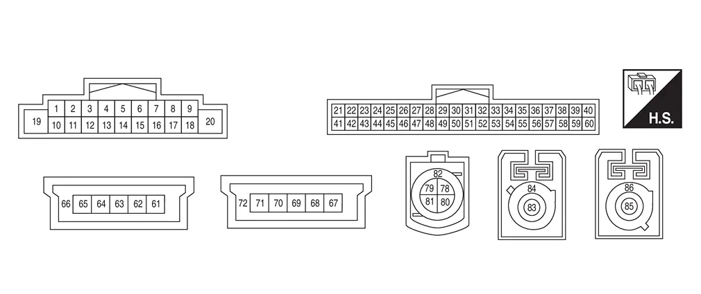
PHYSICAL VALUES
|
Terminal (Wire color) | Description | Condition | Standard |
Reference value (Approx.) | ||
|---|---|---|---|---|---|---|
| + | ŌĆō | Signal name | Input/Output | |||
|
2 (V) |
3 (SB) |
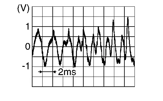
Sound signal front LH | Output |
[Ignition switch ON]
|
Outputs waveform synchronized with sound. |
|
|
4 (BR) |
5 (Y) |
Sound signal rear LH | Output |
[Ignition switch ON]
|
Outputs waveform synchronized with sound. |
|
|
11 (LA/Y) |
12 (LA/G) |
Sound signal front RH | Output |
[Ignition switch ON]
|
Outputs waveform synchronized with sound. |
|
|
13 (LG) |
14 (V) |
Sound signal rear RH | Output |
[Ignition switch ON]
|
Outputs waveform synchronized with sound. |
|
|
19 (LA/G) |
Ground | Battery power supply | Input | [Ignition switch OFF] | 10.8 ŌĆō 15.6 V | Battery voltage |
|
20 (B) |
Ground | Ground | ŌĆö | [Ignition switch ON] | ŌĆö | 0 V |
|
21 (LA/SB) |
ŌĆö | CANŌĆōHigh | Input/Output | ŌĆö | ŌĆö | ŌĆö |
|
22 (LA/SB) |
ŌĆö | AV communication high | Input/Output | ŌĆö | ŌĆö | ŌĆö |
|
23 (LA/SB) |
ŌĆö | AV communication high | Input/Output | ŌĆö | ŌĆö | ŌĆö |
|
28 (R) |
Ground | Camera power supply | Output |
[Ignition switch ON]
|
5.5 - 6.5 V | 6.0 V |
|
29 (B) |
Ground | Camera ground | ŌĆö | [Ignition switch ON] | ŌĆö | 0 V |
|
311 (Shield) |
ŌĆö | Telematics microphone signal shield | ŌĆö | ŌĆö | ŌĆö | ŌĆö |
|
321 (LG)2 (W)3 |
521 (V)2 (B)3 |
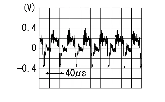
Telematics microphone signal | Input |
[Ignition switch ON]
|
Inputs waveform synchronized with sound |
|
|
39 (W)2 (V)3 |
Ground | Microphone power supply | Output | [Ignition switch ON] | 4.0 - 5.3 V | 5.0 V |
|
40 (B) 1, 4 (LG) 5 |
59 (Shield) |
Microphone signal 1 | Input |
[Ignition switch ON]
|
Inputs waveform synchronized with sound |
|
|
41 (LA/V) |
ŌĆö | CANŌĆōLow | Input/Output | ŌĆö | ŌĆö | ŌĆö |
|
42 (LA/LG) |
ŌĆö | AV communication low | Input/Output | ŌĆö | ŌĆö | ŌĆö |
|
43 (LA/LG) |
ŌĆö | AV communication low | Input/Output | ŌĆö | ŌĆö | ŌĆö |
|
48 (Shield) |
ŌĆö | Camera signal shield | ŌĆö | ŌĆö | ŌĆö | ŌĆö |
|
49 (W) |
Ground | Camera image signal | Input |
[Ignition switch ON]
|
Input the waveform synchronized with the rear view camera image. |
|
|
51 (LA/V) |
Ground | Mode change signal | Output |
[Ignition switch ON]
|
ŌĆö | 5 V |
|
[Ignition switch ON]
|
ŌĆö | 0 V | ||||
|
61 (B) |
ŌĆö | USB ground | ŌĆö | ŌĆö | ŌĆö | ŌĆö |
|
63 (G) |
ŌĆö | USB D+ signal | ŌĆö | ŌĆö | ŌĆö | ŌĆö |
|
64 (W) |
ŌĆö | USB DŌłÆ signal | ŌĆö | ŌĆö | ŌĆö | ŌĆö |
|
65 (R) |
ŌĆö | V BUS signal | ŌĆö | ŌĆö | ŌĆö | ŌĆö |
|
66 (Shield) |
ŌĆö | Shield | ŌĆö | ŌĆö | ŌĆö | ŌĆö |
|
67 (B) |
ŌĆö | USB ground | ŌĆö | ŌĆö | ŌĆö | ŌĆö |
|
69 (G) |
ŌĆö | USB D+ signal | ŌĆö | ŌĆö | ŌĆö | ŌĆö |
|
70 (W) |
ŌĆö | USB DŌłÆ signal | ŌĆö | ŌĆö | ŌĆö | ŌĆö |
|
71 (R) |
ŌĆö | V BUS signal | ŌĆö | ŌĆö | ŌĆö | ŌĆö |
|
72 (Shield) |
ŌĆö | Shield | ŌĆö | ŌĆö | ŌĆö | ŌĆö |
|
78 (R) |
ŌĆö | LVDS ŌłÆ | Input/Output | ŌĆö | ŌĆö | ŌĆö |
|
81 (B) |
ŌĆö | LVDS + | Input/Output | ŌĆö | ŌĆö | ŌĆö |
|
82 (Shield) |
ŌĆö | Shield | ŌĆö | ŌĆö | ŌĆö | ŌĆö |
|
83 (B) |
ŌĆö | AM-FM main | Input | ŌĆö | ŌĆö | ŌĆö |
| 84 | ŌĆö | Shield | ŌĆö | ŌĆö | ŌĆö | ŌĆö |
|
85 (B) |
ŌĆö | Satellite antenna signal | Input | ŌĆö | ŌĆö | ŌĆö |
| 86 | ŌĆö | Shield | ŌĆö | ŌĆö | ŌĆö | ŌĆö |

1: With telematics
2: USA production
3: Japan production
4: USA production without telematics
5: Japan production without telematics
Fail-Safe
If a malfunction occurs in the NissanConnect, AV control unit performs fail-safe activation according to the detected malfunction.
| DTC | NissanConnect operation in fail-safe mode | |
|---|---|---|
| B130B | 11/12/13/1C | Audio output is stopped. |
| B130D | 11/12/13/1C | |
| B130F | 11/12/13/1C | |
| B1311 | 11/12/13/1C | |
| B1315 | 11/13 | Radio is not received. |
| B1328 | 12/13 | Microphone is inoperative. |
| B132A | 01/13 | USB is inoperative. |
| B132C | 01/13 | Telematics system function can not be used. |
| B1339 | 8F | Rear view camera image is not displayed |
| B1341 | 16 | Shut down for battery protection one minute after low voltage condition. |
| B1341 | 17 |
|
| B1341 | 98 | The AV control unit dose not operate until the system cools down. |
| B1346 | 13 | Nissan Ariya Vehicle positions of the navigation screen differ. |
| B1347 | 49 | Bluetooth®is not available |
| B1351 | 4B | AV control unit does not operate. |
| B1360 | 02 | Steering switch does not operate. |
| B1375 | 11/12/13 | Rear view camera is inoperative |
| B1383 | 01 | Predictive course line is not displayed. |
| B13CF | 73 | If a button jam exists, the complete device is locked for 3 minutes. |
| B13D9 | 8F | USB is inoperative. |
| B13DA | 8F | Camera image is not displayed. |
| B13E5 | 8F | Communication with the telematics system is disconnected for more than 20 seconds. |
| B13EC | 52/55 | A function of AV control unit becomes mismatched with a Nissan Ariya vehicle specification and destination. |
| U1000 | 01 | The system using the CAN communication signal from control unit which cannot communicate does not function. |
| U1300 | 01 | The system of ECU which detected abnormalities does not operate. |
DTC Inspection Priority Chart
If multiple DTCs are detected simultaneously, check them one by one depending on the following DTC inspection priority chart.
| Priority | Detected items (DTC) |
|---|---|
| 1 |
|
| 2 |
|
| 3 |
|
| 4 |
|
DTC Index
Self Diagnostic Result
| DTC | Display item | Refer to |
|---|---|---|
| B130B-11 | Rear RH speaker | DTC Description |
| B130B-12 | Rear RH speaker | DTC Description |
| B130B-13 | Rear RH speaker | DTC Description |
| B130B-1C | Rear RH speaker | DTC Description |
| B130D-11 | Front RH speaker | DTC Description |
| B130D-12 | Front RH speaker | DTC Description |
| B130D-13 | Front RH speaker | DTC Description |
| B130D-1C | Front RH speaker | DTC Description |
| B130F-11 | Front LH speaker | DTC Description |
| B130F-12 | Front LH speaker | DTC Description |
| B130F-13 | Front LH speaker | DTC Description |
| B130F-1C | Front LH speaker | DTC Description |
| B1311-11 | Rear LH speaker | DTC Description |
| B1311-12 | Rear LH speaker | DTC Description |
| B1311-13 | Rear LH speaker | DTC Description |
| B1311-1C | Rear LH speaker | DTC Description |
| B1315-11 | AM/FM 1 antenna | DTC Description |
| B1315-13 | AM/FM 1 antenna | DTC Description |
| B1317-11 | XM antenna connection | DTC Description |
| B1317-13 | XM antenna connection | DTC Description |
| B1321-13 | Front Speaker, RH | DTC Description |
| B1322-13 | Front Speaker, LH | DTC Description |
| B1328-12 | External microphone 1 | DTC Description |
| B1328-13 | External microphone 1 | DTC Description |
| B132A-01 | External USB | DTC Description |
| B132A-13 | External USB | DTC Description |
| B132C-01 | TCU connection | DTC Description |
| B132C-13 | TCU connection | DTC Description |
| B1339-8F | Rear camera | DTC Description |
| B1341-16 | Head unit | DTC Description |
| B1341-17 | Head unit | DTC Description |
| B1341-55 | Head Unit | DTC Description |
| B1341-98 | Head unit | DTC Description |
| B1342-62 | ECU signal | DTC Description |
| B1347-49 | Bluetooth module | DTC Description |
| B1351-4B | AV control unit | DTC Description |
| B1360-02 | Combination meter | DTC Description |
| B1375-11 | Rear camera | DTC Description |
| B1375-12 | Rear camera | DTC Description |
| B1375-13 | Rear camera | DTC Description |
| B1383-01 | Steering angle sensor | DTC Description |
| B13CF-73 | Control switch | DTC Description |
| B13D9-8F | USB communication | DTC Description |
| B13DA-8F | LVDS | DTC Description |
| B13E5-8F | TCU connection | DTC Description |
| B13EC-52 | Factory mode | DTC Description |
| B13EC-55 | Factory mode | DTC Description |
Network-DTC
| DTC | Display item | Refer to |
|---|---|---|
| U0079-00 | Control module comm Bus G Off | DTC Description |
| U1000-01 | CAN COMM CIRCUIT | DTC Description |
| U1300-01 | AV communication circuit | DTC Description |
| U2118-87 | CAN comm err (Intelligent Key) | DTC Description |
| U2148-87 | CAN comm err (brake control unit) | DTC Description |
| U214E-87 | CAN comm err (combination meter) | DTC Description |
| U214F-87 | CAN comm err (BCM) | DTC Description |
| U215B-87 | CAN comm err (IPDM E/R) | DTC Description |
| U2164-87 | CAN comm err (DPC/driver seat) | DTC Description |
| U2165-87 | CAN comm err (sonar) | DTC Description |
| U216B-87 | CAN comm err (front camera) | DTC Description |
| U2175-87 | CAN comm err (AVM) | DTC Description |
| U2176-87 | CAN comm err (CCM) | DTC Description |
Nissanconnect with 12.3" Color Display
Reference Value
VALUES ON THE DIAGNOSIS TOOL
NOTE:
The following table includes information (items) inapplicable to this Nissan Ariya vehicle. For information (items) applicable to this vehicle, refer to CONSULT display items.
| Monitor Item | Condition | Value/Status | |
|---|---|---|---|
| Auto ACC |
It depends on Nissan Ariya vehicle architecture. |
On/Off | |
| ACC | Ignition switch ACC | On | |
| Ignition switch OFF | Off | ||
| Aux IN 1 | Ignition switch ON | Accessory connected to USB. | Connnected |
| Accessory not connected to USB. | Not connected | ||
| Parking brake | Ignition switch ON | Parking brake applied. | On |
| Parking brake not applied. | Off | ||
| TCU mute signal | Ignition switch ON | TCU sending mute signal. | On |
| TCU not sending mute signal. | Off | ||
| REVERSE SIGNAL | Ignition switch ON | Selector lever in R position. | On |
| Selector lever in any position other than R. | Off | ||
| ILLUMINATION SIGNAL | Ignition switch ON | Illumination signal received. | On |
| Illumination signal not received. | Off | ||
| Sunload sensor | Ignition switch ON | On | |
| Off | |||
| IGN SIGNAL | Ignition switch ON | On | |
| Ignition switch OFF | Off | ||
| Illumination Control | Ignition switch ON | Illumination control signal received. | % |
TERMINAL LAYOUT
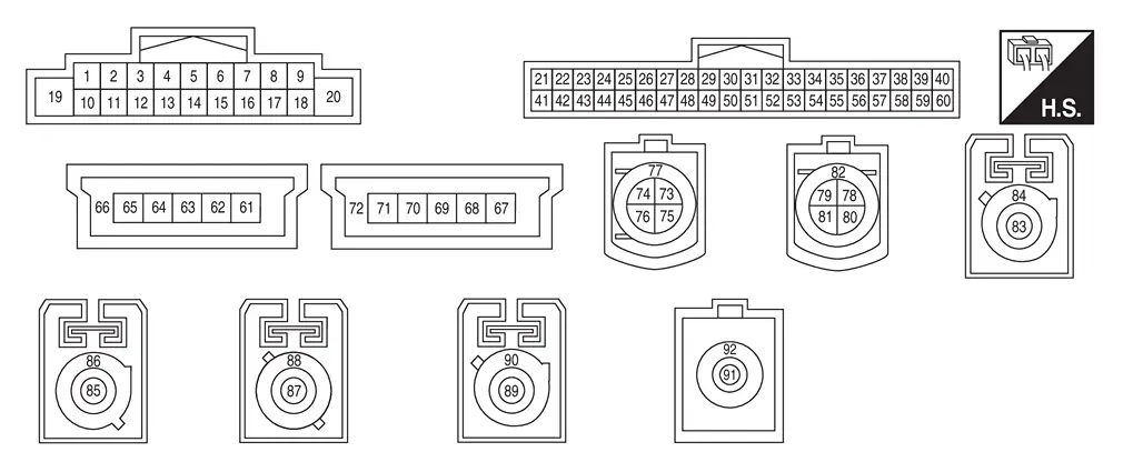
PHYSICAL VALUES (Without BOSE)
|
Terminal (Wire color) | Description | Condition | Standard |
Reference value (Approx.) | ||
|---|---|---|---|---|---|---|
| + | ŌĆō | Signal name | Input/Output | |||
|
2 (G) |
3 (R) |
Sound signal front LH | Output |
[Ignition switch ON]
|
Outputs waveform synchronized with sound. |
|
|
4 (BR) |
5 (Y) |
Sound signal rear LH | Output |
[Ignition switch ON]
|
Outputs waveform synchronized with sound. |
|
|
11 (W) |
12 (B) |
Sound signal front RH | Output |
[Ignition switch ON]
|
Outputs waveform synchronized with sound. |
|
|
13 (LG) |
14 (V) |
Sound signal rear RH | Output |
[Ignition switch ON]
|
Outputs waveform synchronized with sound. |
|
|
19 (LA/G) |
Ground | Battery power supply | Input | [Ignition switch OFF] | 10.8 ŌĆō 15.6 V | Battery voltage |
|
20 (B) |
Ground | Ground | ŌĆö | [Ignition switch ON] | ŌĆö | 0 V |
|
21 (LA/SB) |
ŌĆö | CANŌĆōHigh | Input/Output | ŌĆö | ŌĆö | ŌĆö |
|
22 (LA/SB) |
ŌĆö | AV communication high | Input/Output | ŌĆö | ŌĆö | ŌĆö |
|
23 (LA/SB) |
ŌĆö | AV communication high | Input/Output | ŌĆö | ŌĆö | ŌĆö |
|
31 (Shield) |
ŌĆö | Telematics microphone signal shield | ŌĆö | ŌĆö | ŌĆö | ŌĆö |
|
32 (LG)1 (W)2 |
52 (V)1 (B)2 |
Telematics microphone signal | Input |
[Ignition switch ON]
|
Inputs waveform synchronized with sound |
|
|
39 (W)1 (V)2 |
Ground | Microphone power supply | Output | [Ignition switch ON] | 4.0 - 5.3 V | 5.0 V |
|
40 (B) |
59 (Shield) |
Microphone signal 1 | Input |
[Ignition switch ON]
|
Inputs waveform synchronized with sound |
|
|
41 (LA/R)3 (LA/V)4 |
ŌĆö | CANŌĆōLow | Input/Output | ŌĆö | ŌĆö | ŌĆö |
|
42 (LA/LG) |
ŌĆö | AV communication low | Input/Output | ŌĆö | ŌĆö | ŌĆö |
|
43 (LA/LG) |
ŌĆö | AV communication low | Input/Output | ŌĆö | ŌĆö | ŌĆö |
|
60 (R) |
59 (Shield) |
Microphone signal 2 | Input |
[Ignition switch ON]
|
Inputs waveform synchronized with sound |
|
|
61 (B) |
ŌĆö | USB ground | ŌĆö | ŌĆö | ŌĆö | ŌĆö |
|
63 (G) |
ŌĆö | USB D+ signal | ŌĆö | ŌĆö | ŌĆö | ŌĆö |
|
64 (W) |
ŌĆö | USB DŌłÆ signal | ŌĆö | ŌĆö | ŌĆö | ŌĆö |
|
65 (R) |
ŌĆö | V BUS signal | ŌĆö | ŌĆö | ŌĆö | ŌĆö |
|
66 (Shield) |
ŌĆö | USB shield | ŌĆö | ŌĆö | ŌĆö | ŌĆö |
|
67 (B) |
ŌĆö | USB ground | ŌĆö | ŌĆö | ŌĆö | ŌĆö |
|
69 (G) |
ŌĆö | USB D+ signal | ŌĆö | ŌĆö | ŌĆö | ŌĆö |
|
70 (W) |
ŌĆö | USB DŌłÆ signal | ŌĆö | ŌĆö | ŌĆö | ŌĆö |
|
71 (R) |
ŌĆö | V BUS signal | ŌĆö | ŌĆö | ŌĆö | ŌĆö |
|
72 (Shield) |
ŌĆö | USB shield | ŌĆö | ŌĆö | ŌĆö | ŌĆö |
|
75 (G) |
ŌĆö | Ethernet ŌłÆ | Input/Output | ŌĆö | ŌĆö | ŌĆö |
|
76 (Y) |
ŌĆö | Ethernet + | Input/Output | ŌĆö | ŌĆö | ŌĆö |
|
77 (Shield) |
ŌĆö | Ethernet shield | ŌĆö | ŌĆö | ŌĆö | ŌĆö |
|
79 (B) |
ŌĆö | LVDS ŌłÆ | Input/Output | ŌĆö | ŌĆö | ŌĆö |
|
80 (B) |
ŌĆö | LVDS + | Input/Output | ŌĆö | ŌĆö | ŌĆö |
|
82 (Shield) |
ŌĆö | LVDS shield | ŌĆö | ŌĆö | ŌĆö | ŌĆö |
|
83 (B) |
ŌĆö | AM-FM main | Input | ŌĆö | ŌĆö | ŌĆö |
|
84 (Shield) |
ŌĆö | AM-FM main shield | ŌĆö | ŌĆö | ŌĆö | ŌĆö |
|
85 (B) |
ŌĆö | Satellite antenna signal | Input | ŌĆö | ŌĆö | ŌĆö |
|
86 (Shield) |
ŌĆö | Satellite antenna signal shield | ŌĆö | ŌĆö | ŌĆö | ŌĆö |
|
87 (B) |
ŌĆö | GPS antenna signal | Input | ŌĆö | ŌĆö | ŌĆö |
|
88 (Shield) |
ŌĆö | GPS antenna signal shield | ŌĆö | ŌĆö | ŌĆö | ŌĆö |
|
89 (B) |
ŌĆö | Wifi antenna signal | Input | ŌĆö | ŌĆö | ŌĆö |
|
90 (Shield) |
ŌĆö | Wifi antenna signal shield | ŌĆö | ŌĆö | ŌĆö | ŌĆö |
|
91 (B) |
ŌĆö | Digital camera signal | Input | ŌĆö | ŌĆö | ŌĆö |
|
92 (Shield) |
ŌĆö | Digital camera signal shield | ŌĆö | ŌĆö | ŌĆö | ŌĆö |
1: USA production
2: Japan production
3: With ProPILOT Assist 2.1
4: Without ProPILOT Assist 2.1
PHYSICAL VALUES (With BOSE)
|
Terminal (Wire color) | Description | Condition | Standard |
Reference value (Approx.) | ||
|---|---|---|---|---|---|---|
| + | ŌĆō | Signal name | Input/Output | |||
|
8 (L) |
9 (BG) |
Audio bus | Output | ŌĆö | ŌĆö | ŌĆö |
|
19 (LA/G) |
Ground | Battery power supply | Input | [Ignition switch OFF] | 10.8 ŌĆō 15.6 V | Battery voltage |
|
20 (B) |
Ground | Ground | ŌĆö | [Ignition switch ON] | ŌĆö | 0 V |
|
21 (LA/SB) |
ŌĆö | CANŌĆōHigh | Input/Output | ŌĆö | ŌĆö | ŌĆö |
|
22 (LA/SB) |
ŌĆö | AV communication high | Input/Output | ŌĆö | ŌĆö | ŌĆö |
|
23 (LA/SB) |
ŌĆö | AV communication high | Input/Output | ŌĆö | ŌĆö | ŌĆö |
|
31 (Shield) |
ŌĆö | Telematics microphone signal shield | ŌĆö | ŌĆö | ŌĆö | ŌĆö |
|
32 (W) |
52 (B) |
Telematics microphone signal | Input |
[Ignition switch ON]
|
Inputs waveform synchronized with sound |
|
|
39 (V) |
Ground | Microphone power supply | Output | [Ignition switch ON] | 4.0 - 5.3 V | 5.0 V |
|
40 (B) |
59 (Shield) |
Microphone signal 1 | Input |
[Ignition switch ON]
|
Inputs waveform synchronized with sound |
|
|
41 (LA/R)1 (LA/V)2 |
ŌĆö | CANŌĆōLow | Input/Output | ŌĆö | ŌĆö | ŌĆö |
|
42 (LA/LG) |
ŌĆö | AV communication low | Input/Output | ŌĆö | ŌĆö | ŌĆö |
|
43 (LA/LG) |
ŌĆö | AV communication low | Input/Output | ŌĆö | ŌĆö | ŌĆö |
|
60 (R) |
59 (Shield) |
Microphone signal 2 | Input |
[Ignition switch ON]
|
Inputs waveform synchronized with sound |
|
|
61 (B) |
ŌĆö | USB ground | ŌĆö | ŌĆö | ŌĆö | ŌĆö |
|
63 (G) |
ŌĆö | USB D+ signal | ŌĆö | ŌĆö | ŌĆö | ŌĆö |
|
64 (W) |
ŌĆö | USB DŌłÆ signal | ŌĆö | ŌĆö | ŌĆö | ŌĆö |
|
65 (R) |
ŌĆö | V BUS signal | ŌĆö | ŌĆö | ŌĆö | ŌĆö |
|
66 (Shield) |
ŌĆö | USB shield | ŌĆö | ŌĆö | ŌĆö | ŌĆö |
|
67 (B) |
ŌĆö | USB ground | ŌĆö | ŌĆö | ŌĆö | ŌĆö |
|
69 (G) |
ŌĆö | USB D+ signal | ŌĆö | ŌĆö | ŌĆö | ŌĆö |
|
70 (W) |
ŌĆö | USB DŌłÆ signal | ŌĆö | ŌĆö | ŌĆö | ŌĆö |
|
71 (R) |
ŌĆö | V BUS signal | ŌĆö | ŌĆö | ŌĆö | ŌĆö |
|
72 (Shield) |
ŌĆö | USB shield | ŌĆö | ŌĆö | ŌĆö | ŌĆö |
|
75 (G) |
ŌĆö | Ethernet ŌłÆ | Input/Output | ŌĆö | ŌĆö | ŌĆö |
|
76 (Y) |
ŌĆö | Ethernet + | Input/Output | ŌĆö | ŌĆö | ŌĆö |
|
77 (Shield) |
ŌĆö | Ethernet shield | ŌĆö | ŌĆö | ŌĆö | ŌĆö |
|
79 (B) |
ŌĆö | LVDS ŌłÆ | Input/Output | ŌĆö | ŌĆö | ŌĆö |
|
80 (B) |
ŌĆö | LVDS + | Input/Output | ŌĆö | ŌĆö | ŌĆö |
|
82 (Shield) |
ŌĆö | LVDS shield | ŌĆö | ŌĆö | ŌĆö | ŌĆö |
|
83 (B) |
ŌĆö | AM-FM main | Input | ŌĆö | ŌĆö | ŌĆö |
|
84 (Shield) |
ŌĆö | AM-FM main shield | ŌĆö | ŌĆö | ŌĆö | ŌĆö |
|
85 (B) |
ŌĆö | Satellite antenna signal | Input | ŌĆö | ŌĆö | ŌĆö |
|
86 (Shield) |
ŌĆö | Satellite antenna signal shield | ŌĆö | ŌĆö | ŌĆö | ŌĆö |
|
87 (B) |
ŌĆö | GPS antenna signal | Input | ŌĆö | ŌĆö | ŌĆö |
|
88 (Shield) |
ŌĆö | GPS antenna signal shield | ŌĆö | ŌĆö | ŌĆö | ŌĆö |
|
89 (B) |
ŌĆö | Wifi antenna signal | Input | ŌĆö | ŌĆö | ŌĆö |
|
90 (Shield) |
ŌĆö | Wifi antenna signal shield | ŌĆö | ŌĆö | ŌĆö | ŌĆö |
|
91 (B) |
ŌĆö | Digital camera signal | Input | ŌĆö | ŌĆö | ŌĆö |
|
92 (Shield) |
ŌĆö | Digital camera signal shield | ŌĆö | ŌĆö | ŌĆö | ŌĆö |
1: With ProPILOT Assist 2.1
2: Without ProPILOT Assist 2.1
Fail-Safe
If a malfunction occurs in the NissanConnect, AV control unit performs fail-safe activation according to the detected malfunction.
| DTC | NissanConnect operation in fail-safe mode | |
|---|---|---|
| B1309 | 11/12 | No sound from the speakers. |
| B130B | 11/12/13/1C | Audio output is stopped. |
| B1311 | 11/12/13/1C | |
| B1315 | 11/13 | Radio is not received. |
| B1328 | 12/13 | Microphone is inoperative. |
| B1329 | 12/13 | |
| B132A | 01/13 | USB is inoperative. |
| B132C | 01/13 | Telematics system function can not be used. |
| B1341 | 16 | Shut down for battery protection one minute after low voltage condition. |
| B1341 | 17 |
|
| B1341 | 98 | The AV control unit dose not operate until the system cools down. |
| B1346 | 13 | Nissan Ariya Vehicle positions of the navigation screen differ. |
| B1347 | 49 | Bluetooth®is not available |
| B1351 | 4B | AV control unit does not operate. |
| B1360 | 02 | Steering switch does not operate. |
| B1370 | 02 | Display unit is inoperative. |
| B1383 | 01 | Predictive course line is not displayed. |
| B13CF | 73 | If a button jam exists, the complete device is locked for 3 minutes. |
| B13D9 | 8F | USB is inoperative. |
| B13DA | 8F | Camera image is not displayed. |
| B13E5 | 8F | Communication with the telematics system is disconnected for more than 20 seconds. |
| B13EC | 52/55 | A function of AV control unit becomes mismatched with a Nissan Ariya vehicle specification and destination. |
| U1000 | 88 | The system using the CAN communication signal from control unit which cannot communicate does not function. |
| U1300 | 88 | The system of ECU which detected abnormalities does not operate. |
DTC Inspection Priority Chart
If multiple DTCs are detected simultaneously, check them one by one depending on the following DTC inspection priority chart.
| Priority | Detected items (DTC) |
|---|---|
| 1 |
|
| 2 |
|
| 3 |
|
| 4 |
|
DTC Index
Self Diagnostic Result
| DTC | Display item | Refer to |
|---|---|---|
| B1300-29 | Display error | DTC Description |
| B1306-56 | ECU signal | DTC Description |
| B1307-07 | ECU signal | DTC Description |
| B1309-11 | AV control unit | DTC Description |
| B1309-12 | AV control unit | DTC Description |
| B130B-11 | Rear RH speaker | DTC Description |
| B130B-12 | Rear RH speaker | DTC Description |
| B130B-13 | Rear RH speaker | DTC Description |
| B130B-1C | Rear RH speaker | DTC Description |
| B1311-11 | Rear LH speaker | DTC Description |
| B1311-12 | Rear LH speaker | DTC Description |
| B1311-13 | Rear LH speaker | DTC Description |
| B1311-1C | Rear LH speaker | DTC Description |
| B1314-11 | WiFi antenna | DTC Description |
| B1314-13 | WiFi antenna | DTC Description |
| B1315-11 | AM/FM 1 antenna | DTC Description |
| B1315-13 | AM/FM 1 antenna | DTC Description |
| B1317-11 | XM antenna connection | DTC Description |
| B1317-13 | XM antenna connection | DTC Description |
| B131A-8F | CGW communication | DTC Description |
| B131B-87 | LVDS IN | DTC Description |
| B131B-8F | LVDS IN | DTC Description |
| B131E-49 | ECU GNSS | DTC Description |
| B131F-49 | ECU DSP | DTC Description |
| B1324-49 | ECU CPU | DTC Description |
| B1325-49 | ECU A2B | DTC Description |
| B1326-49 | ECU D-class amp | DTC Description |
| B1328-12 | External microphone 1 | DTC Description |
| B1328-13 | External microphone 1 | DTC Description |
| B1329-12 | External microphone 2 | DTC Description |
| B1329-13 | External microphone 2 | DTC Description |
| B132A-01 | External USB | DTC Description |
| B132A-13 | External USB | DTC Description |
| B132C-01 | TCU connection | DTC Description |
| B132C-13 | TCU connection | DTC Description |
| B132D-49 | ECU eMMC/UFS | DTC Description |
| B132E-49 | ECU PMIC | DTC Description |
| B1330-49 | ECU CP | DTC Description |
| B1331-49 | ECU AVM/RVC | DTC Description |
| B1332-49 | ECU RVC CVBS | DTC Description |
| B1335-8F | A2B communication | DTC Description |
| B1341-16 | Head unit | DTC Description |
| B1341-17 | Head unit | DTC Description |
| B1341-55 | Head Unit | DTC Description |
| B1341-98 | Head unit | DTC Description |
| B1342-62 | ECU signal | DTC Description |
| B1346-11 | GPS antenna circuit | DTC Description |
| B1346-13 | GPS antenna connection | DTC Description |
| B1347-49 | Bluetooth module | DTC Description |
| B1351-49 | ECU D-class amp | DTC Description |
| B1351-4B | AV control unit | DTC Description |
| B1352-47 | ECU signal | DTC Description |
| B1357-29 | ECU signal | DTC Description |
| B1358-29 | ECU signal | DTC Description |
| B1359-06 | ECU signal | DTC Description |
| B135E-49 | ECU fan | DTC Description |
| B1360-02 | Combination meter | DTC Description |
| B1370-02 | 2nd display | DTC Description |
| B1383-01 | Steering angle sensor | DTC Description |
| B13CF-73 | Control switch | DTC Description |
| B13D9-8F | USB communication | DTC Description |
| B13DA-8F | LVDS | DTC Description |
| B13DD-87 | LVDS IN CP | DTC Description |
| B13DD-8F | LVDS IN CP | DTC Description |
| B13E0-47 | ECU signal | DTC Description |
| B13E1-06 | AV unit part number | DTC Description |
| B13E5-8F | TCU connection | DTC Description |
| B13EC-52 | Factory mode | DTC Description |
| B13EC-55 | Factory mode | DTC Description |
| B219D-87 | CAN communication circuit | DTC Description |
| B2E22-06 | FOTA algorythm | DTC Description |
Network-DTC
| DTC | Display item | Refer to |
|---|---|---|
| U0079-00 | Control module comm Bus G Off | DTC Description |
| U1000-88 | CAN Bus Off | DTC Description |
| U1300-88 | CAN Bus M Off | DTC Description |
| U2073-87 | CAN comm circuit | DTC Description |
| U2104-87 | CAN comm circuit | DTC Description |
| U2113-87 | CAN comm circuit | DTC Description |
| U2117-87 | CAN comm circuit | DTC Description |
| U2118-87 | CAN comm err (Intelligent Key) | DTC Description |
| U2119-87 | CAN comm circuit | Diagnosis Procedure |
| U2148-87 | CAN comm err (brake control unit) | DTC Description |
| U214E-87 | CAN comm err (combination meter) | DTC Description |
| U214F-87 | CAN comm err (BCM) | DTC Description |
| U215B-87 | CAN comm err (IPDM E/R) | DTC Description |
| U2162-87 | CAN comm circuit | DTC Description |
| U2165-87 | CAN comm err (sonar) | DTC Description |
| U2167-87 | CAN comm circuit | DTC Description |
| U2169-87 | CAN comm err (PBD) | DTC Description |
| U216B-87 | CAN comm err (front camera) | DTC Description |
| U216E-87 | CAN comm err (SRRR) | DTC Description |
| U2175-87 | CAN comm err (AVM) | DTC Description |
| U2176-87 | CAN comm err (CCM) | DTC Description |
| U2177-87 | PSCU | DTC Description |
| U2181-87 | CAN comm circuit | DTC Description |
| U2187-87 | CAN comm circuit | DTC Description |
| U218C-87 | CAN comm circuit | DTC Description |
| U218D-87 | CAN comm circuit | DTC Description |
| U218E-87 | CAN comm circuit | DTC Description |
| U2194-87 | CAN comm circuit | DTC Description |
| U2195-87 | CAN comm circuit | DTC Description |
| U21A0-87 | CAN comm circuit | DTC Description |
| U21A3-87 | CAN comm circuit | DTC Description |
| U21B6-87 | CAN comm circuit | DTC Description |
| U21BB-87 | CAN comm err | DTC Description |
| U21BE-87 | CAN comm err | DTC Description |
| U224E-87 | CAN comm err (combination meter) | DTC Description |
| U226D-87 | CAN comm err (TCU) | DTC Description |
| U22B8-87 | CAN comm circuit | DTC Description |
| U22B9-87 | CAN comm circuit | DTC Description |
| U2754-88 | Ethernet Link down | DTC Description |
| U2A10-88 | CAN communication | DTC Description |
| U2A13-88 | CAN communication | DTC Description |
Other materials:
U2248 Can Comm Circuit
DTC Description
DTC DETECTION LOGIC DTC
CONSULT screen terms
(Trouble diagnosis content)
DTC detection condition
U2248
83
CAN comm err (brake control unit)
[CAN comm err (brake control unit)]
Diagnosis condition
Ignition switch ON
Signal (terminal)
CAN communicati ...
Engine. Engine Lubrication System
Kr15ddt :: Precaution. Precautions
Precautions
Precaution for Supplemental Restraint System (SRS) "AIR BAG" and SEAT BELT PRE-TENSIONER"
The Supplemental Restraint System such as ŌĆ£AIR BAGŌĆØ and ŌĆ£SEAT BELT
PRE-TENSIONERŌĆØ, used along with a front seat belt, helps to reduce the
risk or se ...
Dtc/circuit Diagnosis. U2176-87 Can Comm Err (ccm/st Angle Sensor)
DTC Description
DESCRIPTIONCAN (Controller Area Network) is a serial
communication line for real time applications. It is an on-Nissan Ariya
vehicle multiplex communication line with high data communication speed
and excellent error detection ability. Modern Nissan Ariya vehicle is
equipped ...