Nissan Rogue (T33) 2021-Present Service Manual: Bose Speaker Amp.
Reference Value
VALUES ON THE DIAGNOSIS TOOL
 NOTE:
NOTE:
The following table includes information (items) inapplicable to this Nissan Ariya vehicle. For information (items) applicable to this vehicle, refer to CONSULT display items.
| Monitor Item | Condition | Value/Status | |
|---|---|---|---|
| Active sound control operating condition | Active sound control system is not operating. | Off | |
| Active sound control system is operating. | On | ||
| Active noise control operating condition | Active noise cancellation system is not operating. | Off | |
| Active noise cancellation system is operating. | On | ||
| Engine speed | Engine running | Almost the same speed as the tachometer indication | |
| Nissan Ariya VehicleSpeed 1 | During vehicle driving | Input value of Nissan Ariya vehicle speed signal | |
TERMINAL LAYOUT
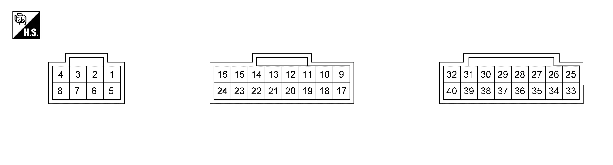
PHYSICAL VALUES
|
Terminal (Wire color) | Description | Condition | Standard |
Reference value (Approx.) | ||
|---|---|---|---|---|---|---|
| + | – | Signal name | Input/Output | |||
|
1 (SB) |
5 (B) |
Battery power supply | Input | [Ignition switch OFF] | 9.0 – 16.0 V | Battery voltage |
|
2 (L) |
6 (P) |
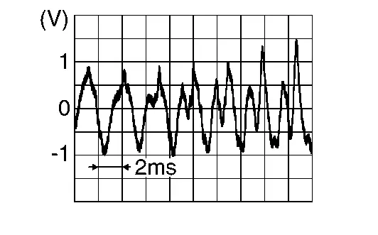
Sound signal front door speaker & front speaker LH | Output |
[Ignition switch ON] Sound signal output |
Outputs waveform synchronized with sound. |
|
|
3 (R) |
7 (G) |
Sound signal front door speaker & front speaker RH | Output |
[Ignition switch ON] Sound signal output |
Outputs waveform synchronized with sound. |
|
|
4 (BR) |
8 (G) |
Sound signal subwoofer 1 | Output |
[Ignition switch ON] Sound signal output |
Outputs waveform synchronized with sound. |
|
|
5 (B) |
Ground | Ground | — | [Ignition switch ON] | — | 0 V |
|
9 (W) |
17 (B) |
Sound signal subwoofer 2 | Output |
[Ignition switch ON] Sound signal output |
Outputs waveform synchronized with sound. |
|
|
10 (L) |
18 (P) |
Sound signal instrument panel speaker LH | Output |
[Ignition switch ON] Sound signal output |
Outputs waveform synchronized with sound. |
|
|
11 (LG) |
19 (V) |
Sound signal instrument panel speaker RH | Output |
[Ignition switch ON] Sound signal output |
Outputs waveform synchronized with sound. |
|
|
12 (B) |
20 (W) |
Sound signal rear door speaker LH | Output |
[Ignition switch ON] Sound signal output |
Outputs waveform synchronized with sound. |
|
|
13 (R) |
21 (G) |
Sound signal rear door speaker RH | Output |
[Ignition switch ON] Sound signal output |
Outputs waveform synchronized with sound. |
|
|
22 (Y) |
14 (P) |
Active noise control microphone LH signal | Input |
[Ignition switch ON] When inputting interior sound |
Inputs waveform synchronized with sound. |
|
|
23 (GR) |
15 (SB) |
Active noise control microphone RH signal | Input |
[Ignition switch ON] When inputting interior sound |
Inputs waveform synchronized with sound. |
|
|
24 (R) |
16 (L) |
Active noise control microphone rear signal | Input |
[Ignition switch ON] When inputting interior sound |
Inputs waveform synchronized with sound. |
|
|
27 (V) |
— | CAN-Low | Input/Output | — | — | — |
|
28 (SB) |
— | CAN-High | Input/Output | — | — | — |
|
29 (LG) |
— | AV communication low | Input/Output | — | — | — |
|
30 (SB) |
— | AV communication high | Input/Output | — | — | — |
|
31 (Y) |
Ground | Engine speed signal | Input | Idle speed | — |
|
|
39 (BG) |
40 (GR) |
Audio bus | Input | — | — | — |
Fail-Safe
If a malfunction occurs in the BOSE audio system, BOSE speaker amp. performs fail-safe activation according to the detected malfunction.
| DTC | Fail-safe mode | |
|---|---|---|
| B1A01 | 11/12/13/1A | Audio output is stopped. |
| B1A05 | 11/12/13/1A | |
| B1A0A | 11/12/13/1A | |
| B1A12 | 11/12/13/1A | |
| B1A2F | 13 | |
| B1A33 | 13 | |
| B1A4C | 11/12/13/1A | |
| B1A50 | 11/12/13/1A | |
| B1A69 | 11/12/13/1A | |
| B1A71 | 11/12/13/1A | |
| B1A80 | 49/4B | Amplifier function is stopped |
| B1F01 | 62 | Active noise cancellation and active sound enhancement are deactivated |
| B1F05 | 29 | |
| B1F21 | 29 | |
| B1F26 | 29 | Active noise cancellation and active sound enhancement are fixed to a standard mode. |
| B1F06 | 29 | Active sound enhancement function is stopped. |
| B1F07 | 29 | |
| B1F20 | 29 | |
| B1F24 | 29 | |
| B1F0B | 01/11/12/13 | Active noise cancellation function is deactivated |
| B1F10 | 01/11/12/13 | |
| B1F15 | 01/11/12/13 | |
| U2140 | 87 | The system using the CAN communication signal from control unit which cannot communicate does not function. |
| U2141 | 87 | |
| U2148 | 87 | |
| U214E | 87 | |
| U214F | 87 | |
| U215B | 87 | |
| B1A80 | 55 | - |
DTC Inspection Priority Chart
If multiple DTCs are detected simultaneously, check them one by one depending on the following DTC inspection priority chart.
| Priority | Detected items (DTC) |
|---|---|
| 1 |
|
| 2 |
|
| 3 |
|
DTC Index
Self Diagnostic Result
| DTC | Display item | Refer to |
|---|---|---|
| B1A01-11 | Front left door woofer out | DTC Description |
| B1A01-12 | Front left door woofer out | DTC Description |
| B1A01-13 | Front left door woofer out | DTC Description |
| B1A01-1A | Front left door woofer out | DTC Description |
| B1A05-11 | Front right door woofer out | DTC Description |
| B1A05-12 | Front right door woofer out | DTC Description |
| B1A05-13 | Front right door woofer out | DTC Description |
| B1A05-1A | Front right door woofer out | DTC Description |
| B1A0A-11 | Front instrument left squawker out | DTC Description |
| B1A0A-12 | Front instrument left squawker out | DTC Description |
| B1A0A-13 | Front instrument left squawker out | DTC Description |
| B1A0A-1A | Front instrument left squawker out | DTC Description |
| B1A12-11 | Front instrument right squawker out | DTC Description |
| B1A12-12 | Front instrument right squawker out | DTC Description |
| B1A12-13 | Front instrument right squawker out | DTC Description |
| B1A12-1A | Front instrument right squawker out | DTC Description |
| B1A2F-13 | Front left pillar tweeter out | DTC Description |
| B1A33-13 | Front right pillar tweeter out | DTC Description |
| B1A4C-11 | Rear left door speaker out | DTC Description |
| B1A4C-12 | Rear left door speaker out | DTC Description |
| B1A4C-13 | Rear left door speaker out | DTC Description |
| B1A4C-1A | Rear left door speaker out | DTC Description |
| B1A50-11 | Rear right door speaker out | DTC Description |
| B1A50-12 | Rear right door speaker out | DTC Description |
| B1A50-13 | Rear right door speaker out | DTC Description |
| B1A50-1A | Rear right door speaker out | DTC Description |
| B1A69-11 | Rear luggage left woofer out | DTC Description |
| B1A69-12 | Rear luggage left woofer out | DTC Description |
| B1A69-13 | Rear luggage left woofer out | DTC Description |
| B1A69-1A | Rear luggage left woofer out | DTC Description |
| B1A71-11 | Rear luggage right woofer out | DTC Description |
| B1A71-12 | Rear luggage right woofer out | DTC Description |
| B1A71-13 | Rear luggage right woofer out | DTC Description |
| B1A71-1A | Rear luggage right woofer out | DTC Description |
| B1A80-49 | ANC UNIT | DTC Description |
| B1A80-4B | ANC UNIT | DTC Description |
| B1A80-55 | ANC UNIT | DTC Description |
| B1F01-62 | ENG SPEED SIG ERROR | DTC Description |
| B1F05-29 | CAN SIG ERROR/DIAG | DTC Description |
| B1F06-29 | CAN SIG ERROR/ASC | DTC Description |
| B1F07-29 | CAN signal error/Mode switching | DTC Description |
| B1F0B-01 | ANC MIC 1 INPUT | DTC Description |
| B1F0B-11 | ANC MIC 1 INPUT | DTC Description |
| B1F0B-12 | ANC MIC 1 INPUT | DTC Description |
| B1F0B-13 | ANC MIC 1 INPUT | DTC Description |
| B1F10-01 | ANC MIC 2 INPUT | DTC Description |
| B1F10-11 | ANC MIC 2 INPUT | DTC Description |
| B1F10-12 | ANC MIC 2 INPUT | DTC Description |
| B1F10-13 | ANC MIC 2 INPUT | DTC Description |
| B1F15-01 | ANC MIC 3 INPUT | DTC Description |
| B1F15-11 | ANC MIC 3 INPUT | DTC Description |
| B1F15-12 | ANC MIC 3 INPUT | DTC Description |
| B1F15-13 | ANC MIC 3 INPUT | DTC Description |
| B1F20-29 | CAN SIG ERROR/ASC | DTC Description |
| B1F21-29 | CAN signal error/ANC | DTC Description |
| B1F24-29 | CAN signal error/ASE | DTC Description |
| B1F26-29 | CAN signal error (TCU) | DTC Description |
Network-DTC
| U2140-87 | CAN comm err (ECM) | DTC Description |
| U2141–87 | CAN comm err (TCM) | DTC Description |
| U2148-87 | CAN comm err (brake control unit) | DTC Description |
| U214E-87 | CAN comm err (combination meter) | DTC Description |
| U214F-87 | CAN comm err (BCM) | DTC Description |
| U215B-87 | CAN comm err (IPDM E/R) | DTC Description |
Other materials:
Plug
Description
Replace the O-ring if oil leaks from the plug.
Exploded View
1.
Plug
2.
O-ring
3.
Plug
4.
O-ring
5.
O-ring
6.
Overflow plug
7.
O-ring
8.
Transaxle assembly
: N·m (kg-m, ft-lb) : N·m (kg-m, in-lb) : Always replace ...
Steering Switch Signal B Circuit
Component Function Check
CHECK COMBINATION METER INPUT SIGNAL
CONSULT
Ignition switch ON.
Select “Steering switch input” in “Data monitor” mode of “M&A”.
Check that the function operates normally according to the following conditions:
Condition Value
CONTRO ...
Three Way Catalyst
Exploded View
Air fuel ratio (A/F) sensor 1
Manifold washer
Stud bolt
Catalyst support bracket
Three way catalyst
Heated oxygen sensor 2
Turbo gasket (OUT)
V-band clamp
Comply with the assembly procedure when tightening. Refer to Remo ...