Nissan Rogue (T33) 2021-Present Service Manual: Wireless Charger :: Ecu Diagnosis Information. Wireless Charger Unit
Wireless Charger Unit
Reference Value
VALUES ON THE DIAGNOSIS TOOL
 NOTE:
NOTE:
The following table includes information (items) inapplicable to this Nissan Ariya vehicle. For information (items) applicable to this vehicle, refer to CONSULT display items.
| Monitor Item | Condition | Value/Status | |
|---|---|---|---|
| Internal temperature | Ignition switch ON | — | Monitors the temperature inside the wireless charger. |
| Object detected | Ignition switch ON | Something is found on the wireless charger. | Yes |
| No objects are found on the wireless charger. | No | ||
| Wireless charger unit is starting up. | Initial | ||
| Wireless charger unit is not receiving a signal. | Inactive | ||
| Receiver detected | Ignition switch ON | A receiver (smartphone etc.) is found on the wireless charger. | Yes |
| No receivers are found on the wireless charger. | No | ||
| Wireless charger unit is starting up. | UNAVAILABLE | ||
| Wireless charger unit is not receiving a signal. | Inactive | ||
| Foreign object detected | Ignition switch ON | When a foreign object is detected on the wireless charger. | Yes |
| When no foreign objects are detected on the wireless charger. | No | ||
| Wireless charger unit is starting up. | UNAVAILABLE | ||
| Wireless charger unit is not receiving a signal. | Inactive | ||
| Charger power status | Ignition switch ON | When the wireless charger is active. | Yes |
| When the wireless charger is inactive. | No | ||
| Wireless charger unit is starting up. | UNAVAILABLE | ||
| Wireless charger unit is not receiving a signal. | Inactive | ||
| Charging State | Ignition switch ON | No charging | No |
| Low speed charging (Max. 5 W) | Low | ||
| Normal charging (Max. 15 W) | Mid | ||
| Wireless charger unit is starting up. | UNAVAILABLE | ||
| Wireless charger unit is not receiving a signal. | Inactive | ||
| Hardware version | Ignition switch ON | Displays a hardware version. | v1.1 — v2.5 |
| When a hardware version cannot be confirmed. | Unknown | ||
| Wireless charger unit is not receiving a signal. | Inactive | ||
| Receiver IC chip ID | Ignition switch ON | — | Displays ID of IC chip on receiver (smartphone etc.). |
| Receiver IC chip manufacturer | Ignition switch ON | When a manufacturer of receiver is Samsung. | Samsung |
| When a manufacturer of receiver is LGE. | LGE | ||
| When a manufacturer of receiver is Nokia. | Nokia | ||
| When a manufacturer of receiver is Motorola. | motorola | ||
| When a manufacturer of receiver is Apple. | Apple | ||
| When a manufacturer of receiver is except for above. | Others | ||
| When manufacturer of receiver cannot be confirmed. | Unknown | ||
| Receiver Qi version | Ignition switch ON | Displays Qi version of receiver (smartphone etc.). | 1.0/1.1/1.2 |
| When Qi version of receiver (smartphone etc.) is except for 1.0, 1.1 or 1.2. | Other | ||
| When Qi version of receiver (smartphone etc.) is unknown. | Unknown | ||
| When unable to detect any receiver (smartphone etc.). | Inactive | ||
| Voltage of charging coil | Ignition switch ON | — | Displays voltage on charging coil. |
| Current of charging coil | Ignition switch ON | — | Displays electric current of charging coil. |
| Input voltage | Ignition switch ON | — | Displays input voltage to charging coil. |
| Input current of charging coil | Ignition switch ON | — | Displays input electric current to charging coil. |
| Charging power consumption | Ignition switch ON | — | Displays power consumption of wireless charger. |
| Receive power (receiver side) | Ignition switch ON | — | Displays power consumption detected from receiver (smartphone etc.). |
| Power loss (charger - receiver) | Ignition switch ON | — | Displays power loss between wireless charger and receiver. |
| Charging Time | Ignition switch ON | — | Displays charging time. |
| Disconnection of charging coil | Ignition switch ON | The coil in the wireless charger is broken. | Yes |
| The coil in the wireless charger is not broken. | No | ||
| Wireless charger unit is starting up. | UNAVAILABLE | ||
| Wireless charger unit is not receiving a signal. | Inactive | ||
| Memory error | Ignition switch ON | Wireless charger is detecting a memory error. | Yes |
| Wireless charger is detecting no memory error. | No | ||
| Wireless charger unit is starting up. | UNAVAILABLE | ||
| Wireless charger unit is not receiving a signal. | Inactive | ||
| Reason of stop charging | Ignition switch ON | A statue of charging being complete. | Charge complete |
| High temperature error. | Type2 | ||
| Foreign object detection error. | Type4 | ||
| Abnormal high voltage input error. | Type6 | ||
| Charge stop request | Ignition switch ON | When not receiving "charge stop request signal" from Intelligent Key unit. | No |
| When receiving "charge stop request signal" from Intelligent Key unit. | Stop | ||
| Wireless charger unit is not receiving a signal. | Inactive | ||
| LED (Orange) | Ignition switch ON | LED (Orange) OFF | Off |
| LED (Orange) ON | On | ||
| Wireless charger unit is starting up. | UNAVAILABLE | ||
| Wireless charger unit is not receiving a signal. | Inactive | ||
| LED (green) | Ignition switch ON | LED (Green) OFF | Off |
| LED (Green) ON | On | ||
| Wireless charger unit is starting up. | UNAVAILABLE | ||
| Wireless charger unit is not receiving a signal. | Inactive | ||
| Firmware Version | Ignition switch ON | Displays firmware version. | v1.1 — v2.5 |
| When firmware version is unknown. | Unknown | ||
| When firmware version cannot be detected. | Inactive | ||
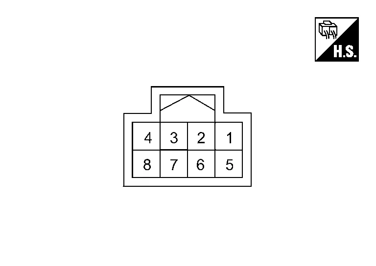
TERMINAL LAYOUT
PHYSICAL VALUES
PHYSICAL VALUES
|
Terminal No. (Wire color) | Description | Condition | Standard | Reference value | |||
|---|---|---|---|---|---|---|---|
| + | – | Signal name | Input/ Output | ||||
|
1 (LA/Y) |
Ground | Ignition power supply | Input | Ignition switch ON | 9.0 — 16.0 V | Battery power supply | |
|
2 (LA/SB) |
Ground | CAN-H | Input/ Output | Ignition switch ON | — | — | |
|
4 (LA/B) |
Ground | Ground | — | Ignition switch ON | — | Approx. 0 V | |
|
5 (GR) |
Ground | Wireless charger indicator ground | — | Ignition switch ON | — | Approx. 0 V | |
|
6 (LA/V) |
Ground | CAN-L | Input/ Output | Ignition switch ON | — | — | |
|
7 (G) |
5 (GR) |
Wireless charger indicator (green) signal | Output |
|
— | Approx. 3.0 V | |
|
— | Approx. 0 V | |||||
|
8 (P) |
5 (GR) |
Wireless charger indicator (orange) signal | Output |
|
— | Approx. 2.0 V | |
|
— | Approx. 0 V | |||||
Fail-safe
|
DTC Display contents of CONSULT | Fail-safe condition |
|---|---|
| B1B00-08 CAN COMMUNICATION | Wireless charger unit does not work |
| B1B01-1C Wireless charger unit | |
| B1B02-1D Wireless charger unit | |
| B1B03-49 Wireless charger unit | |
| U0079-00 Control module comm Bus G Off | |
| U214F-87 CAN comm err (BCM) | |
| U2118-87 CAN comm err (Intelligent Key) | |
| U214E-87 CAN comm err (combination meter) | |
| U215B-87 CAN comm err (IPDM E/R) | |
| U2148-87 CAN comm err (brake control unit) |
DTC Inspection Priority Chart
If multiple DTCs are detected simultaneously, check them one by one depending on the following DTC inspection priority chart.
| Priority | Detected items (DTC) |
|---|---|
| 1 |
|
| 2 |
|
DTC Index
Self Diagnostic Result
| DTC | Display contents of CONSULT | Reference | |
|---|---|---|---|
| B1B00-08 | CAN COMMUNICATION | DTC Description | |
| B1B01-1C | Wireless charger unit | DTC Description | |
| B1B02-1D | Wireless charger unit | DTC Description | |
| B1B03-49 | Wireless charger unit | DTC Description | |
| B1B05-09 | Wireless charger unit | DTC Description | |
Network-DTC
| DTC | Display contents of CONSULT | Reference | |
|---|---|---|---|
| U0079-00 | Control module comm Bus G Off | DTC Description | |
| U214F-87 | CAN comm err (BCM) | DTC Description | |
| U2118-87 | CAN comm err (Intelligent Key) | DTC Description | |
| U214E-87 | CAN comm err (combination meter) | DTC Description | |
| U215B-87 | CAN comm err (IPDM E/R) | DTC Description | |
| U2148-87 | CAN comm err (brake control unit) | DTC Description | |
Other materials:
Automatic Brake Hold. Removal and Installation
Chassis Control Module
Removal and Installation
Removal and installation procedure of chassis control module. Refer to Removal and Installation.
Automatic Brake Hold Switch
Removal and Installation
Removal and installation procedure of parking brake switch. Refer to Removal and Installation.NOTE: ...
P11aa Vcr Position Learning
DTC Description
DTC DETECTION LOGIC DTC
CONSULT screen terms
(Trouble diagnosis content)
DTC detection condition
P11AA
00
VCR position learning
(Variable compression ratio position learning)
Diagnosis condition
Ignition switch ON
Signal (terminal)
—
Thresho ...
Precaution. Precautions
Precaution for Supplemental Restraint System (SRS) "AIR BAG" and "SEAT BELT PRE-TENSIONER"
The Supplemental Restraint System such as “AIR BAG” and “SEAT BELT
PRE-TENSIONER”, used along with a front seat belt, helps to reduce the
risk or severity of injury to the driver and front passeng ...