Nissan Rogue (T33) 2021-Present Service Manual: Wireless Charger :: Basic Inspection. Diagnosis and Repair Work Flow
Diagnosis and Repair Work Flow
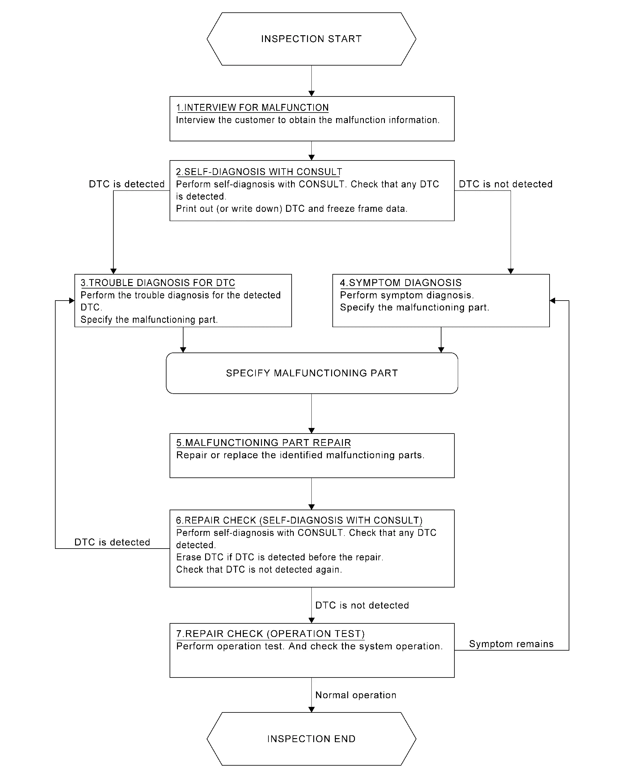
Work Flow
OVERALL SEQUENCE
DETAILED FLOW
INTERVIEW FOR MALFUNCTION
It is also important to clarify the customer concerns before starting the inspection. Interview the customer about the concerns carefully and understand the symptoms fully.
 NOTE:
NOTE:
The customers are not professionals. Never assume that тАЬmaybe the customer means┬╖┬╖┬╖тАЭ or тАЬmaybe the customer mentioned this symptomтАЭ.
>>
GO TO 2.
SELF-DIAGNOSIS WITH CONSULT
 CONSULT
Perform self-diagnosis of тАЬWireless charger". Refer to CONSULT Function.
NOTE:
Skip to step 4 of the diagnosis procedure if тАЬWireless chargerтАЭ is not displayed.
Is any DTC detected?
YES>>GO TO 3.
NO>>GO TO 4.
TROUBLE DIAGNOSIS FOR DTC
CONSULT
-
Check the DTC indicated in the тАЬSelf diagnosis resultтАЭ.
-
When DTC is detected, follow the instructions below:
-
Record DTC
-
Freeze Frame Data (FFD)
-
-
Perform the relevant diagnosis referring to the DTC Index. Refer to DTC Index.
>>
GO TO 5.
SYMPTOM DIAGNOSIS
Perform the applicable diagnosis according to the diagnosis chart by symptom. Refer to Symptom Table.
>>
GO TO 5.
MALFUNCTIONING PART REPAIR
Repair or replace the identified malfunctioning parts.
>>
GO TO 6.
REPAIR CHECK (SELF-DIAGNOSIS WITH CONSULT)
CONSULT
-
Erases self-diagnosis results.
-
Perform self-diagnosis of тАЬWireless chargerтАЭ again after repairing or replacing the specific items.
-
Check if any DTC is detected in self-diagnosis results of тАЬWireless chargerтАЭ .
Is any DTC detected?
YES>>GO TO 3.
NO>>GO TO 7.
REPAIR CHECK (OPERATION TEST)
Perform operation test. Check that the malfunction symptom is solved or no other symptoms occur.
Is there a malfunction symptom?
YES>>GO TO 4.
NO>>Inspection End.
Other materials:
Syst├иme d'essuie-glace automatique avec d├йtecteur de pluie du Nissan Rogue
Le Nissan Rogue est dot├й d'une technologie de d├йtection de pr├йcipitations intelligente. Ce syst├иme d'essuie-glace automatique, assist├й par un capteur de pluie optique situ├й sur la partie sup├йrieure du pare-brise (derri├иre le r├йtroviseur int├йrieur), est capable d'activer les balais sa ...
System Description. System (back Door Opener System)
System Description
SYSTEM DIAGRAM Component Function
Back door opener switch
Refer to Back Door Opener Switch.
Back door opener actuator
Refer to Back Door Lock Assembly.
ABS actuator and electric unit (control unit)
Transmit Nissan Ariya vehicle speed signal to BCM via CAN c ...
Installing top tether strap
WARNING
Child restraint anchorages are designed only for correctly installed restraints. Never attach adult seat belts or other equipment to these pointsтАФdoing so may damage the anchors and compromise safety.
Avoid hooking the tether strap on the seatback carpet. Always use the designated ...