Nissan Rogue (T33) 2021-Present Service Manual: Unit Removal and Installation :: Steering Gear and Linkage
Exploded View
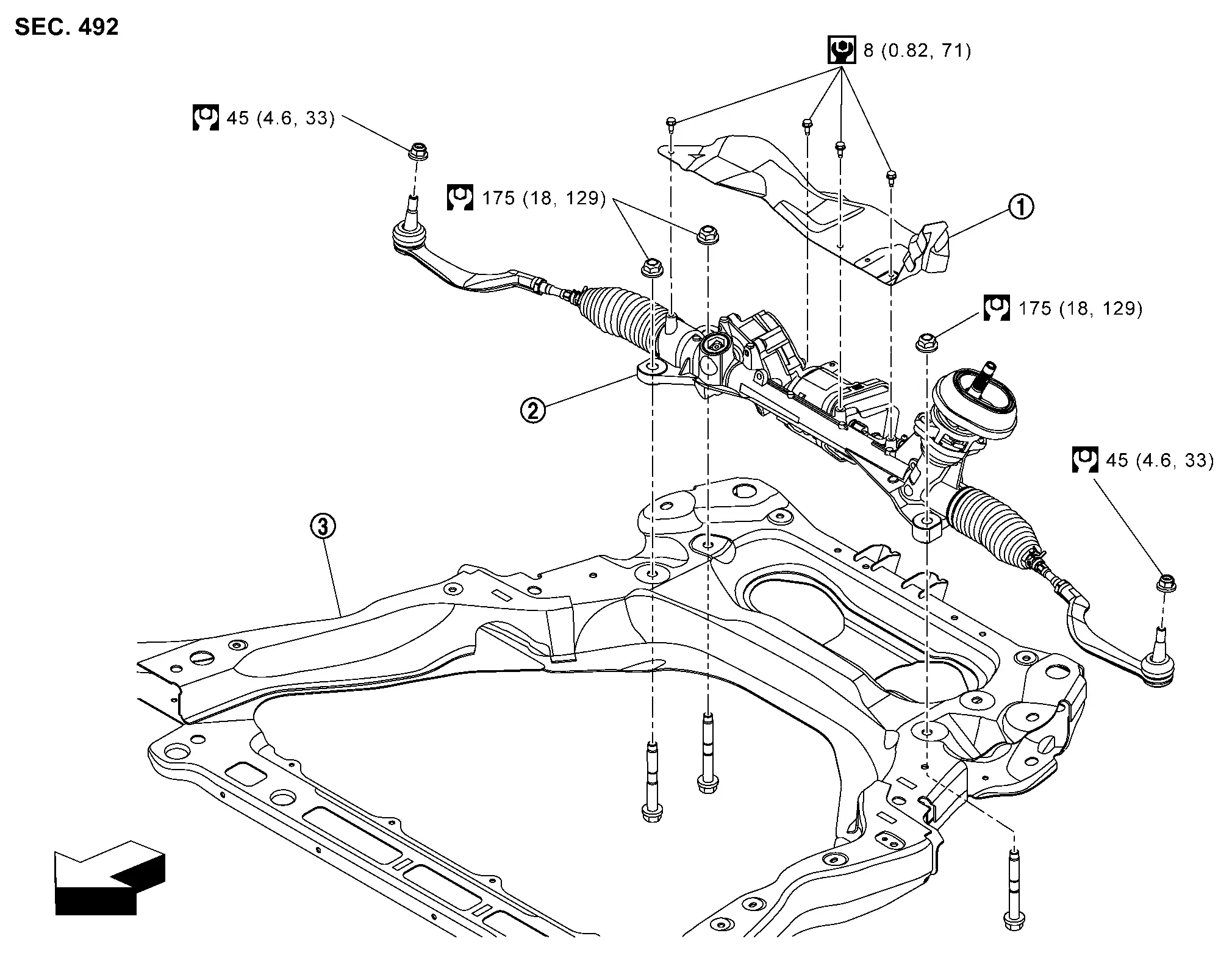
REMOVAL (JAPAN PRODUCTION MODELS)
 |
Heat insulator |  |
Steering gear assembly |  |
Front suspension member |
| : Nissan Ariya Vehicle front | |||||
 |
: N·m (kg-m, ft-lb) | ||||
 |
: N·m (kg-m, in-lb) | ||||
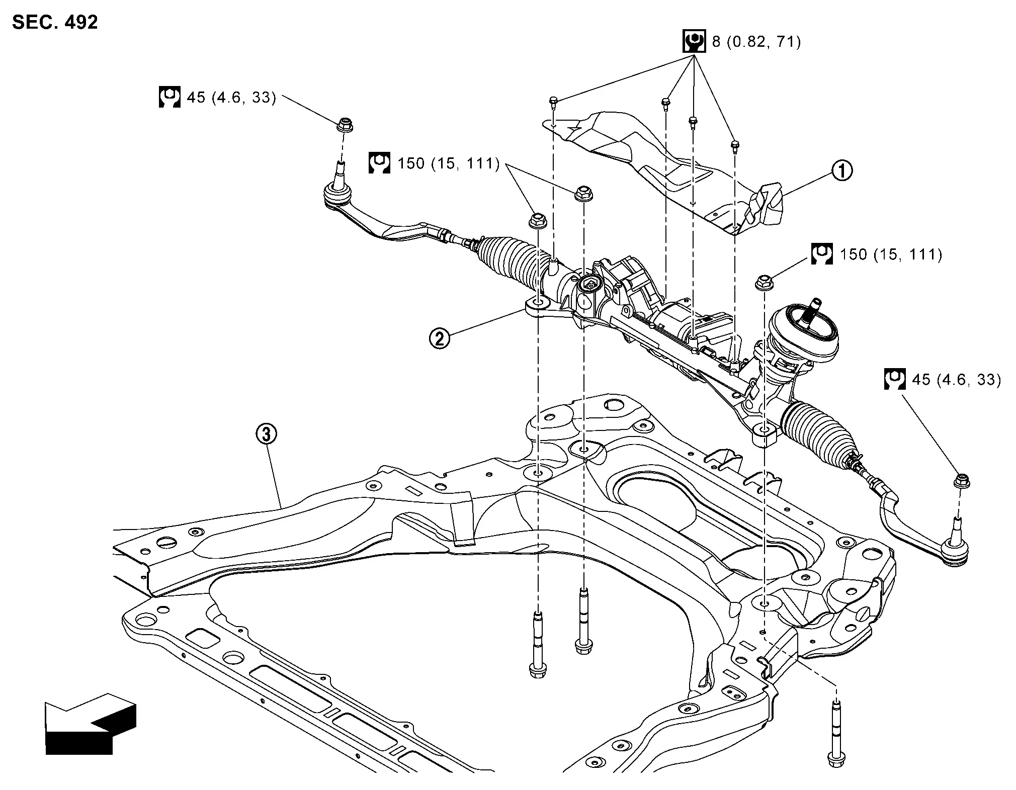
REMOVAL (NORTH AMERICA PRODUCTION MODELS)
|
Heat insulator | |
Steering gear assembly | |
Front suspension member |
| : Nissan Ariya Vehicle front | |||||
|
: N·m (kg-m, ft-lb) | ||||
|
: N·m (kg-m, in-lb) | ||||
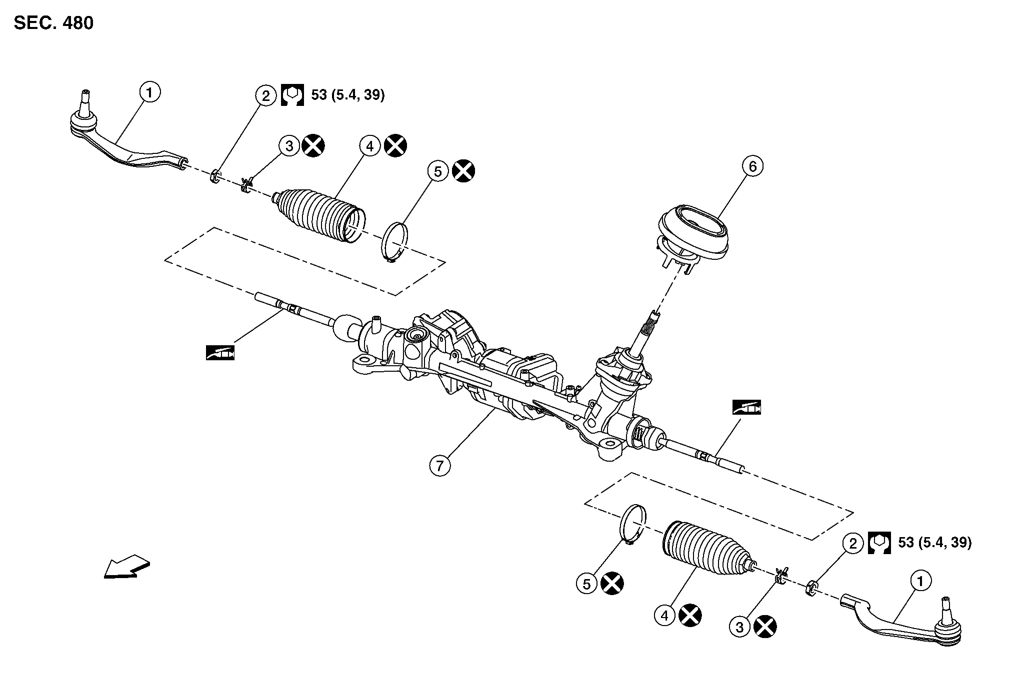
DISASSEMBLY (JAPAN PRODUCTION MODELS)
|
Outer socket | |
Outer socket lock nut | |
Boot clamp (small diameter) |
 |
Boot |  |
Boot clamp (large diameter) |  |
Hole cover seal |
 |
Gear housing assembly | ||||
|
: N·m (kg-m, ft-lb) | ||||
 |
: Apply Dow Corning 111 or equivalent. | ||||
 |
: Always replace after every disassembly. | ||||
CAUTION:
Never apply the grease to the surface between steering rack and inner socket screw part.
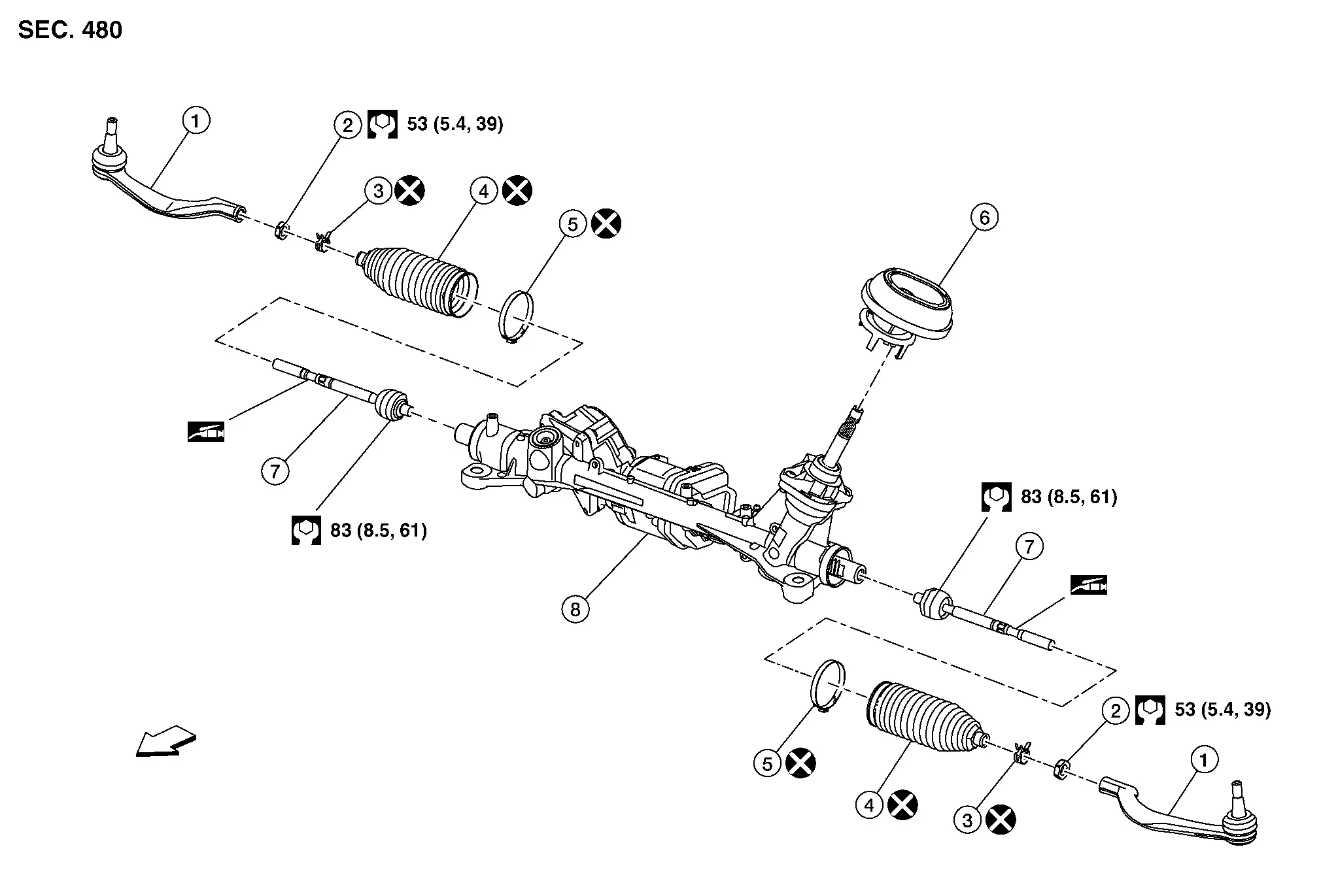
DISASSEMBLY (NORTH AMERICA PRODUCTION MODELS)
|
Outer socket | |
Outer socket lock nut | |
Boot clamp (small diameter) |
|
Boot | |
Boot clamp (large diameter) | |
Hole cover seal |
|
Inner socket |  |
Gear housing assembly | ||
|
: N·m (kg-m, ft-lb) | ||||
|
: Apply Dow Corning 111 or equivalent. | ||||
|
: Always replace after every disassembly. | ||||
CAUTION:
Never apply the grease to the surface between steering rack and inner socket screw part.
Removal and Installation
CAUTION:
Never disconnect or pull the torque sensor harness (A) and harness connector (B).
Without ProPILOT Assist 2.1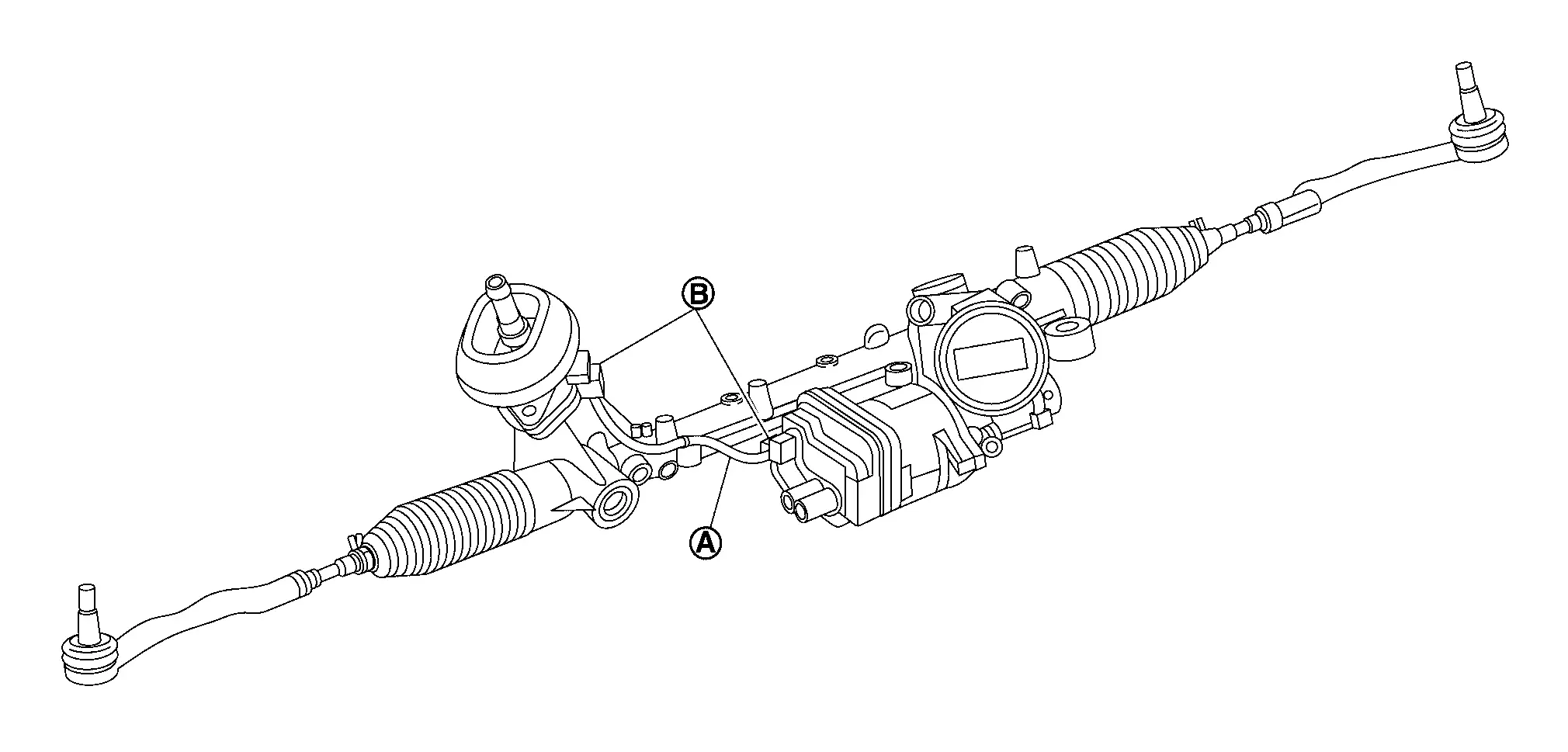
With ProPILOT Assist 2.1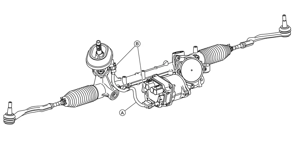
REMOVAL
Perform "ADDITIONAL SERVICE WHEN REPLACING POWER STEERING CONTROL MODULE CONTROL UNIT". Refer to Work Procedure.
Set Nissan Ariya vehicle to the straight-ahead position.
Remove front suspension member. Refer to Removal and Installation.
Remove front stabilizer bar. Refer to Removal and Installation.
Remove steering gear assembly.
INSTALLATION
Note the following, and install in the reverse order of removal.
CAUTION:
-
Spiral cable may be cut if steering wheel turns while separating steering column assembly and steering gear assembly. Always fix the steering wheel using string to avoid turning.
-
Before installation, check that the tilt position is at the middle level.
-
Clean mounting surface on the body side of hole cover seal when installing steering gear assembly.
-
Perform final tightening of nuts and bolts on each part under unladen conditions with tires on level ground when removing steering gear assembly. Check wheel alignment.
-
Rotate steering wheel to check for decentered condition, binding, noise or excessive steering effort.
-
Perform inspection after installation. Refer to Inspection.
-
Perform "ADDITIONAL SERVICE WHEN REPLACING POWER STEERING CONTROL MODULE CONTROL UNIT". Refer to Work Procedure.
-
If equipped with ProPILOT Assist, perform steering torque calibration after replacing or removing and installing the steering gear assembly. Refer to Work Procedure.
Inspection
INSPECTION AFTER DISASSEMBLY (JAPAN PRODUCTION MODELS)
Boot
-
Check boot for cracks, and replace it if a malfunction is detected.
Gear Housing Assembly
-
Check gear housing assembly for damage and scratches. Replace if there are any abnormal conditions.
Outer Socket and Inner Socket
-
Check the following items and replace the component if it does not meet the standard.
BALL JOINT SWINGING FORCE
-
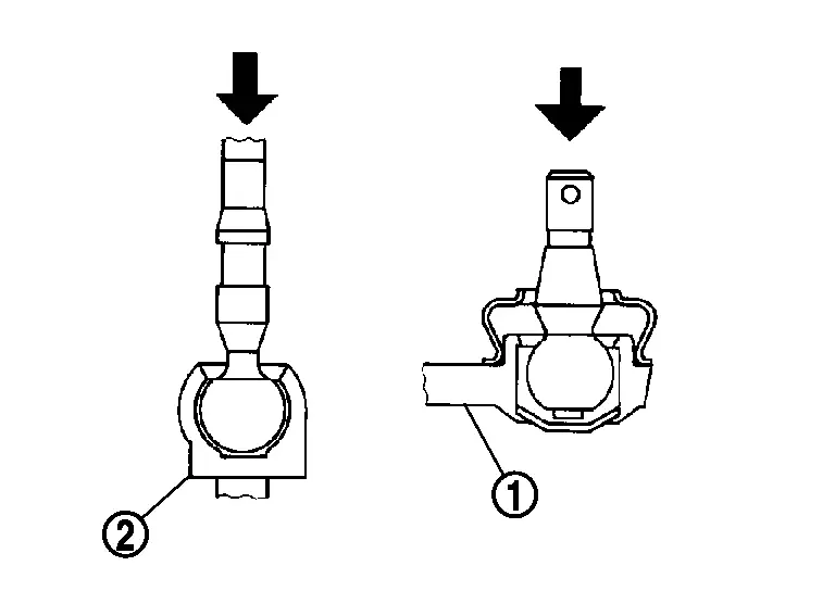
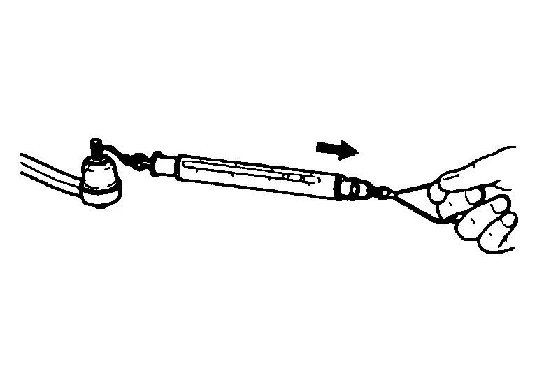
Hook a pull gauge [SST: — (NI-44372)] at the point shown in the figure and pull the pull gauge. Make sure that the pull gauge reads the specified value when ball stud and inner socket start to move. Replace outer socket and inner socket if they are outside the standard.
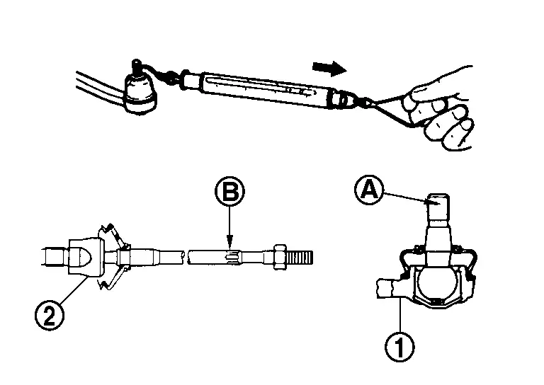
Measuring point of outer socket (1) Ball stud upper side (A) Measuring point of inner socket (2) Point (B) shown in the figure Swinging force : Refer to Steering Gear and Linkage.
BALL JOINT ROTATING TORQUE
-
Make sure that the reading is within the following specified range using suitable tool (A). Replace outer socket if the reading is outside the specification.
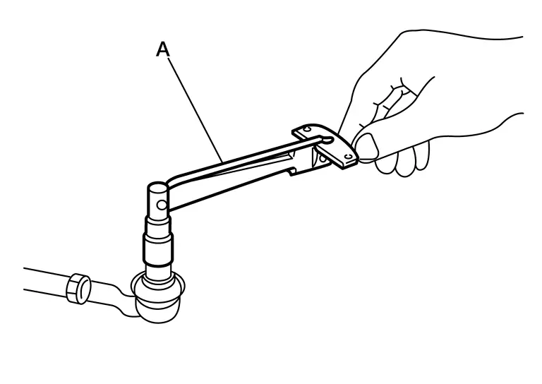
Rotating torque : Refer to Steering Gear and Linkage.
BALL JOINT AXIAL END PLAY
-
Apply an axial load of 490 N (50 kg, 110 lb) to ball stud. Using a dial gauge, measure amount of stud movement, and then make sure that the value is within the following specified range. Replace outer socket (1) and inner socket (2) if the measured value is outside the standard.
Axial end play : Refer to Steering Gear and Linkage.
INSPECTION AFTER DISASSEMBLY (NORTH AMERICA PRODUCTION MODELS)
Boot
-
Check boot for cracks, and replace it if a malfunction is detected.
Gear Housing Assembly
-
Check gear housing assembly for damage and scratches. Replace if there are any abnormal conditions.
Outer Socket and Inner Socket
-
Check the following items and replace the component if it does not meet the standard.
BALL JOINT SWINGING FORCE
-
Hook a pull gauge [SST: — (NI-44372)] at the point shown in the figure and pull the pull gauge. Make sure that the pull gauge reads the specified value when ball stud and inner socket start to move. Replace outer socket and inner socket if they are outside the standard.
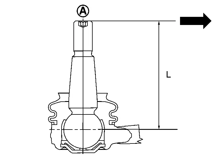
Measuring point of outer socket -
Ball stud upper side (A)
-
Moment arm length (L): 71.5 mm (2.815 in)
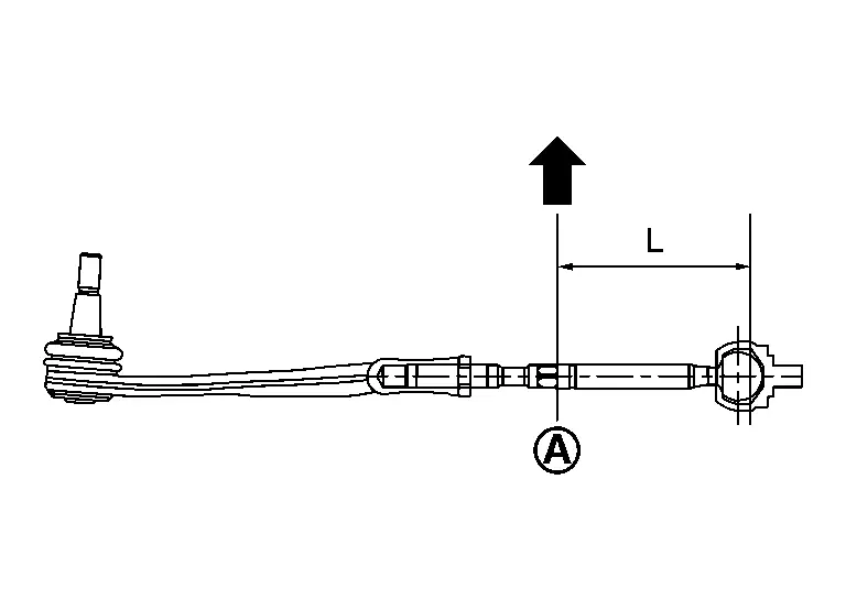
Measuring point of inner socket -
Point shown in the figure (A)
-
Moment arm length (L): 105 mm (4.13 in)
Swinging force : Refer to Steering Gear and Linkage. -
BALL JOINT ROTATING TORQUE
-
Make sure that the reading is within the following specified range using suitable tool (A). Replace outer socket if the reading is outside the specification.
Rotating torque : Refer to Steering Gear and Linkage.
BALL JOINT AXIAL END PLAY
-
Apply an axial load of 490 N (50 kg, 110 lb) to ball stud. Using a dial gauge, measure amount of stud movement, and then make sure that the value is within the following specified range. Replace outer socket (1) and inner socket (2) if the measured value is outside the standard.
Axial end play : Refer to Steering Gear and Linkage.
INSPECTION AFTER INSTALLATION
-
Check if steering wheel turns smoothly when it is turned several times fully to the end of the left and right.
-
Check the steering wheel play, neutral position steering wheel, steering wheel turning force, and front wheel turning angle.
-
Steering wheel play: Refer to Steering Wheel.
-
Neutral position steering wheel, steering wheel turning force, and front wheel turning angle: Refer to Steering Wheel.
-
Other materials:
Dtc/circuit Diagnosis. Intelligent Key Battery
Component Inspection
CHECK INTELLIGENT KEY BATTERY
Check by connecting a resistance (approximately 300 Ω) so that the
current value becomes about 10 mA. Refer to Removal and Installation.
Standard
: Approx. 2.5 - 3.0 V
Is the measurement value within the specification?
YES>> ...
P2614 Intake Camshaft Position Sensor
DTC Description
DTC DETECTION LOGIC DTC
CONSULT screen terms
(Trouble diagnosis content)
DTC detection condition
P2614
00
A camshaft posi signal B1
(Camshaft A Position Signal Output Circuit/Open Bank 1 )
A
Diagnosis condition
Engine running at idle
Signal (termin ...
How to Use This Manual. Recommended Chemical Products and Sealants
Recommended Chemical Products and Sealants
Refer to the following chart for help in selecting the appropriate chemical product or sealant. Product Description Purpose Nissan North America Part No. (USA) Nissan Canada Part No. (Canada) Aftermarket Cross-reference Part Nos.
1
Rear Vie ...