Nissan Rogue (T33) 2021-Present Service Manual: Unit Disassembly and Assembly :: Steering Gear and Linkage
Exploded View
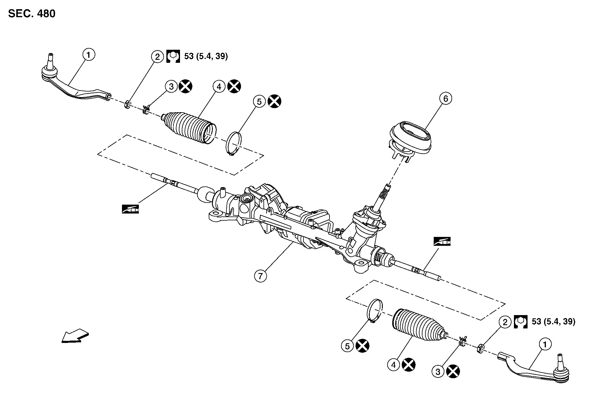
DISASSEMBLY (NORTH AMERICA PRODUCTION MODELS)
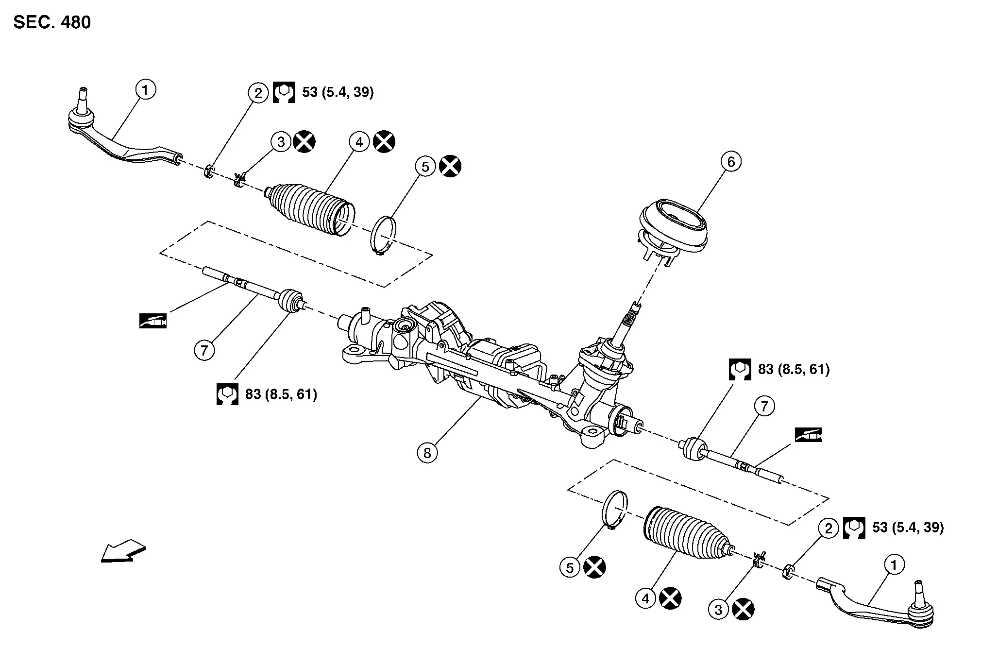
DISASSEMBLY (JAPAN PRODUCTION MODELS)
 |
Outer socket |  |
Outer socket lock nut |  |
Boot clamp (small diameter) |
 |
Boot |  |
Boot clamp (large diameter) |  |
Hole cover seal |
 |
Gear housing assembly | ||||
 |
: N·m (kg-m, ft-lb) | ||||
 |
: Apply Dow Corning 111 or equivalent. | ||||
 |
: Always replace after every disassembly. | ||||
CAUTION:
Never apply the grease to the surface between steering rack and inner socket screw part.
DISASSEMBLY (NORTH AMERICA PRODUCTION MODELS)
| 1. | Outer socket | 2. | Outer socket lock nut | 3. | Boot clamp (small diameter) |
| 4. | Boot | 5. | Boot clamp (large diameter) | 6. | Hole cover seal |
| 7. | Inner socket | 8. | Gear housing assembly | ||
|
: N·m (kg-m, ft-lb) | ||||
|
: Apply Dow Corning 111 or equivalent. | ||||
|
: Always replace after every disassembly. | ||||
CAUTION:
Never apply the grease to the surface between steering rack and inner socket screw part.
Disassembly and Assembly
DISASSEMBLY (JAPAN PRODUCTION MODELS)
CAUTION:
Disassemble and assemble steering gear assembly by fixing the mounting area with a vise using copper plates.
Loosen inner socket lock nut (A).
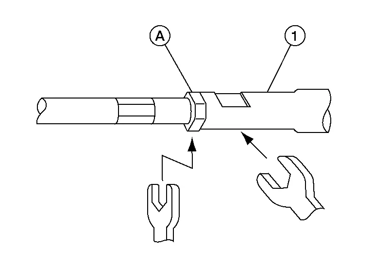
CAUTION:
To prevent damage, hold outer socket (1) across flats using suitable tool while loosening inner socket lock nut (A).
Remove boot clamps, and then remove boot from inner socket and housing.
CAUTION:
Never damage inner socket part of gear housing assembly when removing boot. Steering gear assembly must be replaced if gear housing assembly are damaged because it may cause foreign material interfusion.
Remove hole cover seal.
Perform inspection after disassembly. Refer to Inspection.
DISASSEMBLY (NORTH AMERICA PRODUCTION MODELS)
CAUTION:
Disassemble and assemble steering gear assembly by fixing the mounting area with a vise using copper plates.
Loosen inner socket lock nut (A).
CAUTION:
To prevent damage, hold outer socket (1) across flats using suitable tool while loosening inner socket lock nut (A).
Remove boot clamps, and then remove boot from inner socket and housing.
CAUTION:
Never damage inner socket part of gear housing assembly when removing boot. Steering gear assembly must be replaced if gear housing assembly are damaged because it may cause foreign material interfusion.
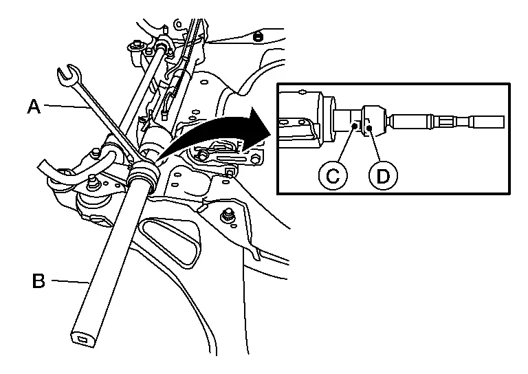
Remove the inner socket.
CAUTION:
To prevent damage to the steering gear when installing the inner socket, hold suitable tool (A) across steering gear flats (C) while turning suitable tool (B) across inner socket flats (D).
Remove hole cover seal.
Perform inspection after disassembly. Refer to Inspection.
ASSEMBLY (JAPAN PRODUCTION MODELS)
Install hole cover seal to gear housing assembly.
Apply recommended grease to part (A) of inner socket, and install boot to inner socket and gear housing.
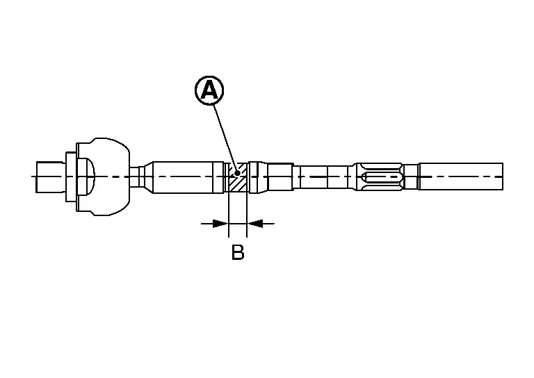
Use Dow Corning 111 (manufactured by TOURE·DAUKONINGU) or equivalent.
CAUTION:
Never reuse boot.
| Grease application position (Reference) | |
| B | : 10 mm (0.39 in) |
Install boot clamp (large diameter) (1) to boot using boot band crimping tool (SST: KV40107300) (A).
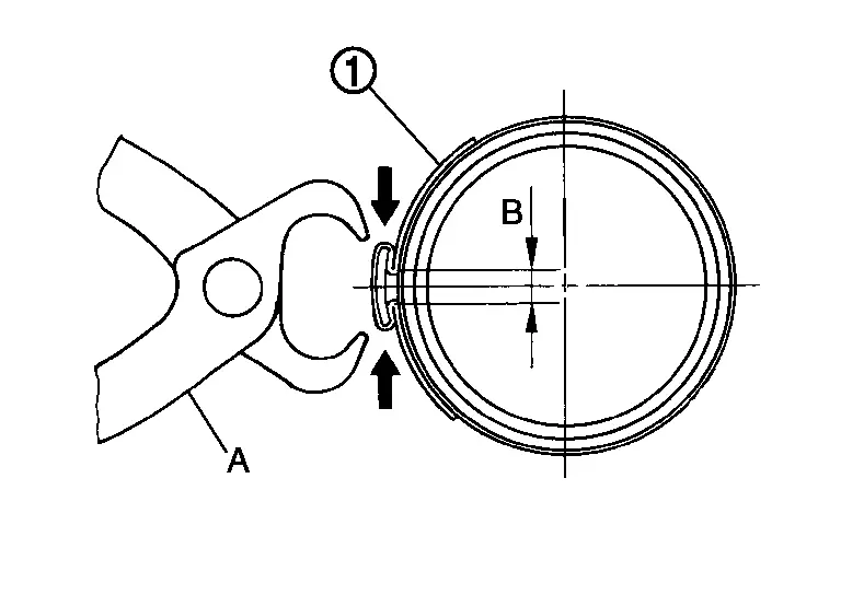
CAUTION:
-
Never reuse boot clamp (large diameter).
-
Install boot clamp (large diameter) securely to boot groove, and crimp it so as to have clearance (B) of 3 mm (0.12 in) or less as shown.
Install boot clamp (small diameter) to boot.
Adjust inner socket to standard length (L), and then tighten lock nut to the specified torque. Check length again after tightening lock nut.
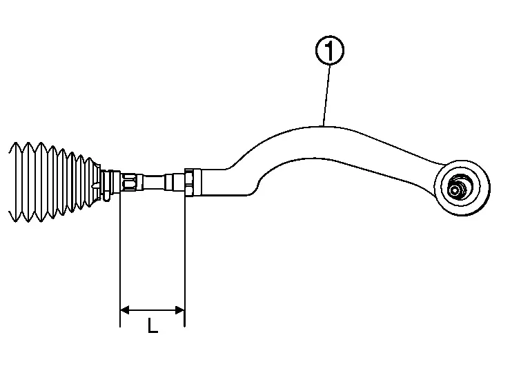
| 1. | : Outer socket |
| Inner socket length (L) | : Steering Gear and Linkage |
CAUTION:
-
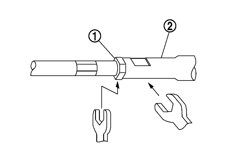
When tightening the lock nut (1), be sure to fix outer socket (2) with a wrench or an equivalent to prevent the ball joint from getting contact with the knuckle.
-
Adjust toe-in after this procedure. The length achieved after toe-in adjustment is not necessarily the above value.
ASSEMBLY (NORTH AMERICA PRODUCTION MODELS)
Install hole cover seal to gear housing assembly.
Install inner socket. Tighten to specified torque. Refer to Exploded View.
CAUTION:
To prevent damage to the steering gear when installing the inner socket, hold suitable tool (A) across steering gear flats (C) while turning suitable tool (B) across inner socket flats (D).
Apply recommended grease to part (A) of inner socket, and install boot to inner socket and gear housing.
Use Dow Corning 111 (manufactured by TOURE·DAUKONINGU) or equivalent.
CAUTION:
Never reuse boot.
| Grease application position (Reference) | |
| B | : 10 mm (0.39 in) |
Install boot clamp (large diameter) (1) to boot using boot band crimping tool (SST: KV40107300) (A).
CAUTION:
-
Never reuse boot clamp (large diameter).
-
Install boot clamp (large diameter) securely to boot groove, and crimp it so as to have clearance (B) of 3 mm (0.12 in) or less as shown.
Install boot clamp (small diameter) to boot.
Adjust inner socket to standard length (L), and then tighten lock nut to the specified torque. Check length again after tightening lock nut.
| 1. | : Outer socket |
| Inner socket length (L) | : Steering Gear and Linkage |
CAUTION:
-
When tightening the lock nut (1), be sure to fix outer socket (2) with a wrench or an equivalent to prevent the ball joint from getting contact with the knuckle.
-
To prevent damage, hold outer socket across flats using suitable tool while tightening inner socket lock nut.
-
Adjust toe-in after this procedure. The length achieved after toe-in adjustment is not necessarily the above value.
-
Inspect to make sure no boot deformation has occurred during toe-in adjustment. Adjust boot as necessary.
-
Adjust toe-in after this procedure. The length achieved after toe-in adjustment is not necessary the above value.
Other materials:
Manual Air Conditioning. Precaution. Precautions
Precautions
Precaution for Supplemental Restraint System (SRS) "AIR BAG" and "SEAT BELT PRE-TENSIONER"
The Supplemental Restraint System such as “AIR BAG” and “SEAT BELT
PRE-TENSIONER”, used along with a front seat belt, helps to reduce the
risk or severity of injury to the driver and ...
Ecu Diagnosis Information. Moonroof Motor Assembly
Reference Value
TERMINAL LAYOUTPHYSICAL VALUES
Terminal No.
(Wire color) Description Condition
Value
(Approx.)
+ – Signal name Input/Output
1
(B)
Ground
Ground
—
—
0 V
4
(W)
Ground
Moonroof Tilt UP signal
Input
Moonroof switch
Operate
( ...
Handling Precaution
Precautions for Automatic Emergency Braking
DISTANCE SENSOR HANDLINGRefer to Precautions for Intelligent Forward Collision Warning.FRONT CAMERA UNIT HANDLINGRefer to Precautions for Lane Departure Warning.PRECAUTIONS FOR AEBFailure
to follow the warnings and instructions for proper use of the AEB ...