Nissan Rogue (T33) 2021-Present Service Manual: Ecu Diagnosis Information :: Power Steering Control Module
Reference Value
VALUES ON THE DIAGNOSIS TOOL
 NOTE:
NOTE:
The following table includes information (items) inapplicable to this Nissan Ariya vehicle. For information (items) applicable to this vehicle, refer to CONSULT display items.
| Monitor item | Data monitor | ||
|---|---|---|---|
| Condition | Display value | ||
| Steering torque | Engine running |
Steering wheel: Not steering (There is no steering force) |
Approx. 0.0 Nm |
| Steering wheel: Right turn | Negative value (Nm) | ||
| Steering wheel: Left turn | Positive value (Nm) | ||
| Demanded motor current | Engine running |
Steering wheel: Not steering (There is no steering force) |
Approx. 0 A |
| Steering wheel: Left or Right turn | Displays consumption current of EPS motor | ||
| Assist level | Engine running | Not steering assist | 99 %*1 |
| EPS warning | Engine running | EPS system is normal | No error |
| Not used | Error1 | ||
| EPS system malfunction | Error2 | ||
| Demanded assistance torque | Engine running |
Steering wheel: Not steering (There is no steering force) |
Approx. 0.0 Nm |
| Steering wheel: Right turn | Negative value (Nm) | ||
| Steering wheel: Left turn | Positive value (Nm) | ||
| Measured motor current | Engine running |
Steering wheel: Not steering (There is no steering force) |
Approx. 0 A |
| Steering wheel: Left or Right turn | Displays consumption current of EPS motor*2 | ||
| ECU temperature | Ignition switch ON or engine running | Displays temperature of inside of power steering control module | |
| Battery voltage | Ignition switch ON | 10.5 - 16 V | |
| Auto stop start status | Stop start system is inactive | Status1 | |
| Stop start system is active (engine start) | Status2 | ||
| Stop start system is active (engine stop) | Status3 | ||
| Stop start system is active (suspended) | Status4 | ||
| Nissan Ariya Vehicle speed | Vehicle stopped | 0.00 KPH | |
| While driving |
Approximately equal to the indication on speedometer*3 (inside of ┬▒10%) |
||
| ENGINE STATUS | Engine stop | Status1 | |
| Engine running | Status2 | ||
| Engine crnking | Status3 | ||
| Auto stop start sub-sys mode | Displays but not used | ŌĆö | |
| Filter | Displays but not used | ŌĆö | |
| Battery disconnect count | Ignition switch ON | Displays the count of disconnected 12V battery terminal | |
*1: Normally displays 99%. In case of an excessive stationary steering, the assist curvature gradually falls. However, it returns to 99% when left standing.
*2: Almost in accordance with the value of ŌĆ£Target motor currentŌĆØ. It is not a malfunction though these values are not accorded when steering quickly.
*3: It is not a malfunction, though it might not be corresponding just after ignition switch ON.
TERMINAL LAYOUT
(Without ProPILOT Assist 2.1)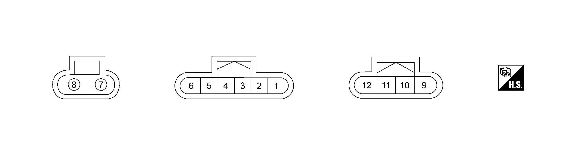
PHYSICAL VALUES
|
Terminal No. (Wire Color) | Description | Condition | Value | |||
|---|---|---|---|---|---|---|
| + | ŌłÆ | Signal name | Input/Output | |||
|
1 (G) |
ŌĆö | Chassis CAN communication-Low | Input/Output | ŌĆö | ŌĆö | |
|
2 (GR) |
ŌĆö | Chassis CAN communication-High | Input/Output | ŌĆö | ŌĆö | |
|
4 (LA/V) |
Ground | Accessory (USA production) | Input | Ignition switch: ON | 10.5 ŌĆō 16 V | |
| Ignition switch: OFF | Approx. 0 V | |||||
|
4 (LA/SB) |
Ground | Accessory (Japan production) | Input | Ignition switch: ON | 10.5 ŌĆō 16 V | |
| Ignition switch: OFF | Approx. 0 V | |||||
|
7 (R) |
Ground | Battery | Input | Always | 10.5 ŌĆō 16 V | |
|
8 (B) |
Ground | Ground | ŌĆö | Always | Approx. 0 V | |
|
9 (R) |
ŌĆö | Torque sensor power supply | Output | Ignition switch: ON | 10.5 - 16 V | |
| Ignition switch: OFF | Approx. 0 V | |||||
|
10 (Y) |
ŌĆö | Torque sensor ground | ŌĆö | ŌĆö | ŌĆö | |
TERMINAL LAYOUT
(With ProPILOT Assist 2.1)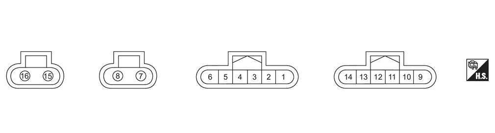
PHYSICAL VALUES
|
Terminal No. (Wire Color) | Description | Condition | Value | |||
|---|---|---|---|---|---|---|
| + | ŌłÆ | Signal name | Input/Output | |||
|
1 (G) |
ŌĆö | CAN-Low | Input/Output | ŌĆö | ŌĆö | |
|
2 (GR) |
ŌĆö | CAN-High | Input/Output | ŌĆö | ŌĆö | |
|
4 (LA/SB) |
Ground | AUTO_ACC | Input | Ignition switch: ON | Battery voltage | |
| Ignition switch: OFF | Approx. 0 V | |||||
|
7 (W) |
Ground | BATT (MAIN) | Input | Always | Battery voltage | |
|
8 (B) |
Ground | GND (MAIN) | ŌĆö | Always | Approx. 0 V | |
|
9 (P) |
ŌĆö | CAN-Low | ŌĆö | ŌĆö | ŌĆö | |
|
10 (GR) |
ŌĆö | CAN-High | ŌĆö | ŌĆö | ŌĆö | |
|
15 (BR) |
Ground | BATTERY (SUB) | Input | Always | Battery voltage | |
|
16 (B) |
Ground | GROUND (SUB) | ŌĆö | Always | Approx. 0 V | |
Fail-Safe
Refer to Fail-Safe.
Protection Function
Refer to Protection Function.
DTC Inspection Priority Chart
When multiple DTCs are detected simultaneously, check one by one depending on the following priority list:
| Priority | Priority order item (DTC) |
|---|---|
| 1 |
|
| 2 |
|
| 3 |
|
| 4 |
|
| 5 |
|
DTC Index
| DTC | Items | Power steering warning lamp | Reference |
|---|---|---|---|
| C1601-16 | BATTERY VOLT | ON | DTC Description |
| C1601-17 | BATTERY VOLT | ON | DTC Description |
| C1604-96 | TORQUE SENSOR | ON | DTC Description |
| C1608-43 | CONTROL UNIT | OFF | DTC Description |
| C1608-46 | CONTROL UNIT | ON | DTC Description |
| C1608-49 | CONTROL UNIT | ON | DTC Description |
| C1608-52 | CONTROL UNIT | OFF | DTC Description |
| C1608-54 | CONTROL UNIT | ON | DTC Description |
| C1615-4B | Control unit over heat | ON | DTC Description |
| C161A-82 | ABS system | OFF | DTC Description |
| C161A-83 | ABS system | OFF | DTC Description |
| C161A-86 | ABS system | OFF | DTC Description |
| C161B-82 | ABS system | OFF | DTC Description |
| C161B-83 | ABS system | OFF | DTC Description |
| C161B-86 | ABS system | OFF | DTC Description |
| C161C-82 | ST angle sensor system | OFF | DTC Description |
| C161C-83 | ST angle sensor system | OFF | DTC Description |
| C161C-86 | ST angle sensor system | OFF | DTC Description |
| C161E-82 | ABS system | OFF | DTC Description |
| C161E-83 | ABS system | OFF | DTC Description |
| C161E-86 | ABS system | OFF | DTC Description |
| C161F-86 | AV system | OFF | DTC Description |
| C1620-82 | Chassis control system | OFF | DTC Description |
| C1620-83 | Chassis control system | OFF | DTC Description |
| C1621-86 | BCM system | OFF | DTC Description |
| C1622-86 | BCM system | OFF | DTC Description |
| C1624-00 | Signal connector | OFF | DTC Description |
| C1632-86 | ST angle sensor system | OFF | DTC Description |
| C1633-86 | VDC system | OFF | DTC Description |
| C1634-86 | ST angle sensor system | OFF | DTC Description |
| C163A-86 | ADAS system | OFF | DTC Description |
| C163E-86 | Chassis control system | OFF | DTC Description |
| U0076-00 | Control module comm Bus D Off | OFF | DTC Description |
| U1321-55 | Configuration data error | ON | DTC Description |
| U2140-87 | CAN comm err (ECM) | OFF | DTC Description |
| U2148-87 | CAN comm err (brake control unit) | OFF | DTC Description |
| U214F-87 | CAN comm err (BCM) | OFF | DTC Description |
| U2156-87 | CAN comm err (steering angle sensor) | OFF | DTC Description |
| U215B-87 | CAN comm err (IPDM E/R) | OFF | DTC Description |
| U2176-87 | CAN comm err (CCM/ST angle sensor) | OFF | DTC Description |
NOTE:
If two or more DTCs are detected, refer to DTC Inspection Priority Chart.
Other materials:
2wd. Preparation. Preparation
Preparation
Special Service Tool
Tool number
(TechMate No.)
Tool name Description
KV40104000
( ŌĆō )
Hub lock nut wrench
a: 85 mm (3.35 in)
b: 65 mm (2.56 in)
Removing and Installing wheel hub lock nut.
KV40107300
( ŌĆō )
Boot band crimping tool
Installing bo ...
Awd. Periodic Maintenance
Rear Wheel Hub and Housing
Inspection
COMPONENT PARTMake sure that the mounting conditions
(looseness, backlash) of each component and component conditions (wear,
damage) are normal.WHEEL HUB ASSEMBLY (BEARING-INTEGRATED TYPE)Check the following items, and replace the part if necessary.
Mov ...
Basic information
The following are approximate capacities for your Nissan Rogue.
Actual refill capacities may vary slightly. When refilling, always follow the procedure described in the "8. Do-it-yourself" section to confirm the proper amount for your Nissan Rogue.
Fuel
Engine oil
Drain and refill
Genuine "NI ...