Nissan Rogue (T33) 2021-Present Service Manual: Operation
Switch Name and Function
OPERATION AND DISPLAY OF MANUAL AIR CONDITIONING SYSTEM
Operation: A/C switch assembly
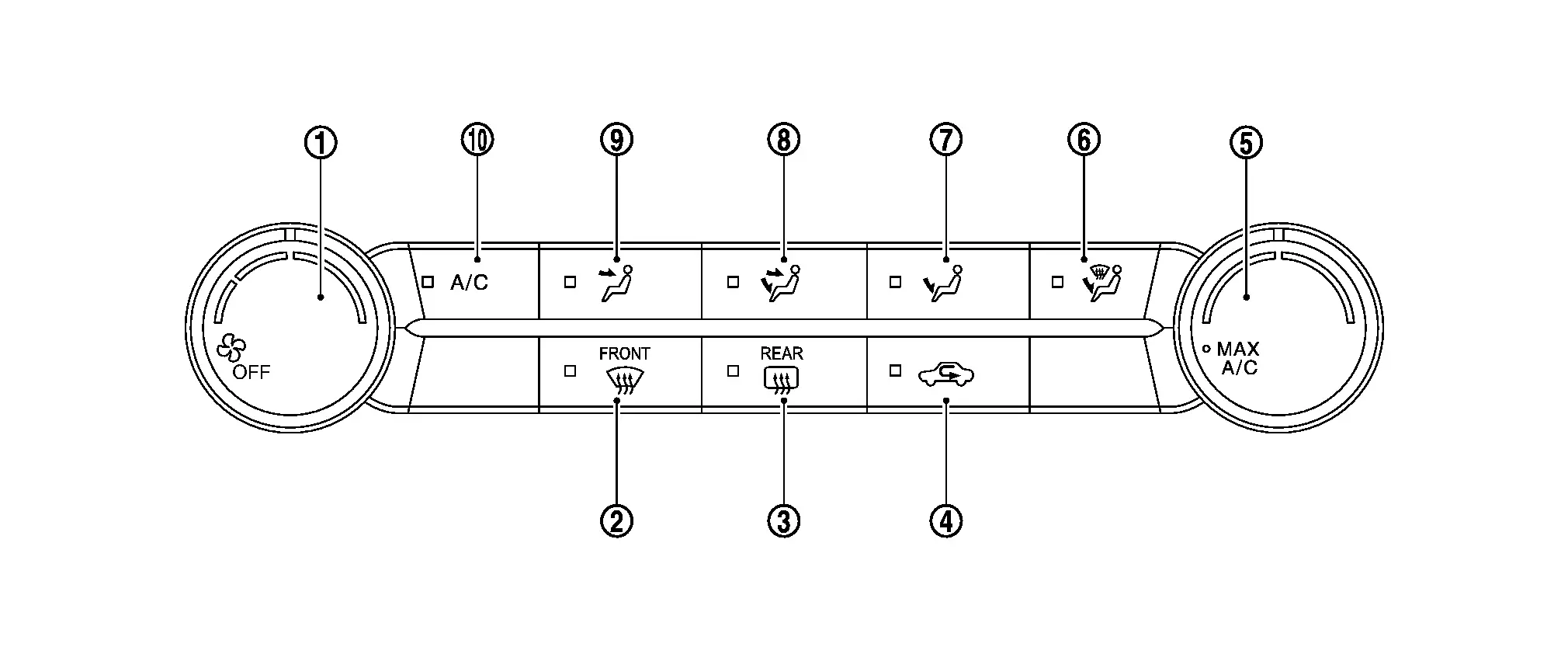
| 1. | Fan control dial | 2. | DEF switch | 3. | Rear window defogger switch |
| 4. | Intake switch | 5. | Temperature control dial | 6. | D/F switch |
| 7. | FOOT switch | 8. | B/L switch | 9. | VENT switch |
| 10. | A/C switch |
| Switch name | Function |
|---|---|
| Fan control dial |
The air flow can be manually set within the range of speeds 1st - 11th by operating the dial.
|
| Rear window defogger switch | Rear window defogger changes between ON ⇔ OFF each time this switch is pressed. For details, refer to System Description. |
| Intake switch |
|
| Temperature control dial |
The air flow temperature can be adjusted by operating the dial.
When MAX A/C position, the air conditioning system changes to the following state:
|
| A/C switch | A/C compressor control changes between ON ⇔ OFF each time this switch is pressed. |
| VENT switch |
|
| B/L switch | |
| FOOT switch | |
| D/F switch | |
| DEF switch |
 NOTE:
NOTE:
Other materials:
Diagnosis System (av Control Unit)
Nissanconnect with 8" Color Display
On Board Diagnosis Function
The AV control unit on board diagnosis performs the functions listed in the table below:DESCRIPTION Mode Description
Self Diagnosis
Audio system diagnosis.
Diagnoses the connections across system components.
...
Symptom Diagnosis. Wiper and Washer System Symptoms
Symptom Table (Without Rain and Light Sensor)
NOTE:
Perform the "Self diagnosis result" with CONSULT before
the symptom diagnosis. Perform the trouble diagnosis if any DTC is
detected.
Symptom Possible cause Inspection item
Front wiper does not operate
HI only
BCM
IPDM E ...
Symptom Diagnosis. Low Tire Pressure Warning Lamp Blinks
Description
When the ignition switch is placed ON, the low tire pressure warning
lamp blinks. And then 1 minute later, low tire pressure warning lamp
turns ON.
Diagnosis Procedure
CHECK TIRE PRESSURE SENSOR INSTALLATION
Check visually that tire pressure sensors are installed to each wheels c ...