Nissan Rogue (T33) 2021-Present Service Manual: System
Manual Air Conditioning System
System Description
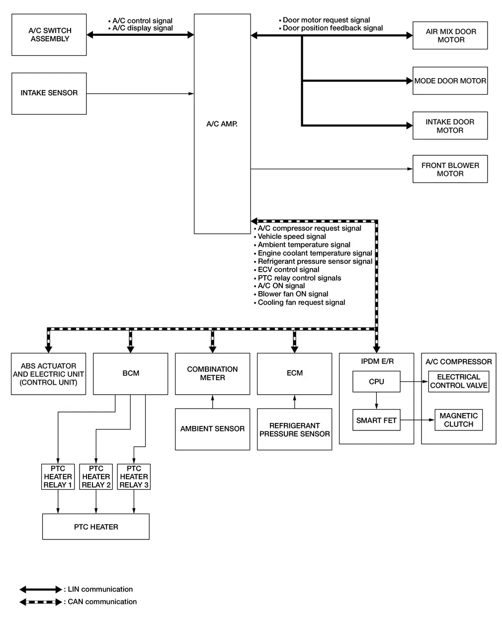
SYSTEM DIAGRAM
| Component | Function |
|---|---|
| ABS actuator and electric unit (control unit) | ABS actuator and electric unit (control unit) transmits Nissan Ariya vehicle speed signal to A/C amp. via CAN communication line. |
| A/C amp. | A/C Amp. |
| BCM | BCM receives each signals, and controls PTC heater relay. |
| Combination meter | Combination meter transmits ambient temperature signal to A/C amp. via CAN communication line. |
| ECM |
|
| IPDM E/R |
|
| A/C switch assembly | A/C Switch Assembly |
| Ambient sensor | Ambient Sensor |
| Intake sensor | Intake Sensor |
| Refrigerant pressure sensor | Refrigerant Pressure Sensor |
| Air mix door motor | Air Mix Door Motor |
| Front blower motor | Front Blower Motor |
| Intake door motor | Intake Door Motor |
| Mode door motor | Mode Door Motor |
| A/C compressor | A/C Compressor |
| PTC heater | PTC Heater |
| PTC heater relay 1/2/3 | PTC Heater Relay |
INPUT SIGNAL AND OUTPUT SIGNAL
| Control unit | Signal status |
|---|---|
| A/C amp. |
|
| ABS actuator and electric unit (control unit) | Transmits the Nissan Ariya vehicle speed signal to A/C amp. via CAN communication. |
| Combination meter | Transmits the ambient temperature signal to A/C amp. via CAN communication. |
| ECM |
|
| BCM | BCM receives each signals, and controls PTC heater relay. |
| IPDM E/R | Receives mainly the ECV control signal from A/C amp. via CAN communication. |
| A/C switch assembly |
|
| Air mix door motor |
|
| Intake door motor | |
| Mode door motor |
DESCRIPTION
-
Manual air conditioning system is controlled by each function of A/C amp., ECM and IPDM E/R.
-
Each operation of air conditioning system can be controlled by the A/C switch assembly.
-
BCM performs PTC heater relay ON/OFF control based on engine speed, engine coolant temperature, ambient temperature, electrical power cut freeze signal (permission signal, retention signal, stop signal), PTC thermal request signal, battery voltage, and electrical load state (high beam request, low beam request, and others).
-
When PTC heater relay turns ON, power supply is supplied to PTC heater. Heating element is heated and air flow temperature is increased. Heating is available for a period of time until engine coolant temperature is increased when engine starts cold in cold climate.
-
Idle up request signal is transmitted from A/C amp. to ECM while PTC heater operates. Idle speed is increased, warming-up is facilitated, and battery electric power is obtained.
-
Electric power supplied to PTC heating element is subject to PTC heater relay control conditions.
PTC heater Operation PTC heater relay 1 PTC heater relay 2 PTC heater relay 3 OFF OFF OFF OFF OFF PTC heater-1 LOW ON OFF OFF PTC heater-2 MID ON ON OFF PTC heater-3 HI ON ON ON
 NOTE:
NOTE:
PTC heater operation depends on ambient temperature and battery voltage. PTC heater is ON when ambient temperature is 8ô¯C (46.4ô¯F) or less. PTC heater is OFF when ambient temperature is 12ô¯C (53.6ô¯F) or more. The operating voltage of the PTC heater ON/OFF changes depending on the electrical load of the Nissan Ariya vehicle or battery voltage.
CONTROL BY A/C AMP.
-
Air Inlet Control
-
Door Control
-
A/C Compressor Control
-
Cooling Fan Operation Request Control
CORRECTION FOR INPUT VALUE
-
Ambient temperature correction
-
A/C amp. inputs the temperature detected by ambient temperature signal received from combination meter via CAN communication as the ambient temperature.
-
A/C amp. performs the correction of the temperature detected by ambient sensor for air conditioning control.
-
A/C amp. selects and uses the initial value of ambient temperature data depending on the engine coolant temperature when placing the ignition switch from OFF to ON. The detection temperature of the ambient sensor is used when engine coolant temperature is low [less than approximately 133ô¯F (56ô¯C)]. The memory data (before the ignition switch is OFF) when the engine is warmed up [approximately 133ô¯F (56ô¯C) or more].
-
The correction of the ambient temperature is not performed when the detection temperature of the ambient temperature is less than approximately ã4ô¯F (ã20ô¯C).
-
-
Intake temperature correction
-
A/C amp. inputs the temperature detected by intake sensor as the intake temperature (evaporator temperature).
-
A/C amp. performs the correction of the temperature detected by intake sensor for air conditioning control.
-
A/C amp. performs the correction so that the recognition intake temperature changes depending on the difference between the detected intake temperature and the recognition intake temperature. If the difference is large, the changing is early. The changing becomes slow as the difference becomes small.
-
CONTROL BY ECM
A/C Compressor Control
CONTROL BY IPDM E/R
A/C Compressor Control
Air Inlet Control
DESCRIPTION
-
A/C amp. controls the intake door motor and switches the air inlets.
-
A/C amp. controls the air inlets so that they are set to fresh air intake, when A/C compressor is stopped by low temperature protection control.
-
When the following conditions are met, A/C amp. controls the air inlets to 20% recirculation. (However, this does not occur when high engine coolant temperature control is in effect.)
At this time, the intake switch indicator lamp turns OFF.
-
Temperature control dial: Full hot
-
Air outlet mode: FOOT or DEF
-
HIGH ENGINE COOLANT TEMPERATURE CONTROL
When the following conditions is met, A/C amp. changes the air inlets to recirculation.
-
Air outlet: Other than D/F or DEF
-
A/C switch: ON
-
Ambient temperature: More than 25ô¯C (77ô¯F)
-
Nissan Ariya Vehicle speed: 18 MPH (30 km/h) or more
-
Engine coolant temperature: 105ô¯C (221ô¯F) or more
Door Control
SWITCH AND THEIR CONTROL FUNCTION

| 1. | Intake door | 2. | In-cabin microfilter | 3. | Front blower motor |
| 4. | Evaporator | 5. | Air mix door | 6. | Heater core |
| 7. | PTC heater | 8. | Foot door | 9. | Ventilator door |
| 10. | Defroster door | ||||
 |
Fresh air |  |
Recirculation air | Discharge air | |
 |
Defroster |  |
Center ventilator |  |
Side ventilator |
 |
Rear ventilator |  |
Front foot |  |
Rear foot |
| Switch/dial position | Door position | |||||||
|---|---|---|---|---|---|---|---|---|
| Mode door | Intake door | Air mix door | ||||||
| Ventilator door | Foot door | Defroster door | ||||||
| VENT switch |  |
.webp) |
 |
|
|
ã | ã | |
| B/L switch |  |
|
 |
|
|
|||
| FOOT switch |  |
|
 |
|
|
|||
| D/F switch |  |
|
|
|
|
|||
| DEF switch |  |
|
|
|
|
|||
| Intake switch | REC |  |
|
ã | ã | ã | |
|
| FRE | .webp) |
|
||||||
| Temperature control dial | Full cold | ã | |
|||||
| Full cold ã Full hot | ã |
|||||||
| Full hot | |
|||||||
AIR DISTRIBUTION
| Discharge air flow | ||||||
|---|---|---|---|---|---|---|
| MODE position | Air outlet/distribution | |||||
| Ventilator | Foot | Defroster | ||||
| Front | Rear | Front | Rear | |||
| Center | Side | |||||
|
45% | 43% | 12% | ã | ã | ã |
|
23% | 27% | 14% | 30% | 6% | ã |
|
ã | 9% | 18% | 36% | 12% | 25% |
|
ã | 8% | 15% | 30% | 11% | 36% |
|
ã | 6% | 15% | ã | ã | 79% |
A/C Compressor Control
DESCRIPTION
-
When the A/C compressor activation condition is satisfied while front blower motor is activated, A/C amp. transmits A/C ON signal and blower fan ON signal to ECM.
-
ECM judges the conditions of each sensor (Refrigerant pressure sensor signal, accelerator position signal, etc.), and transmits the A/C compressor request signal to IPDM E/R via CAN communication line.
-
By receiving the A/C compressor request signal from ECM, IPDM E/R turns the Smart FET to ON, and activates the A/C compressor. Refer to System Description.
CONTROL BY A/C AMP.
Low Temperature Protection Control
When intake sensor detects that evaporator fin temperature is  [23.0ô¯F (ã5.0ô¯C) ] or less, A/C amp. requests ECM to turn the A/C compressor OFF, and stops the A/C compressor.
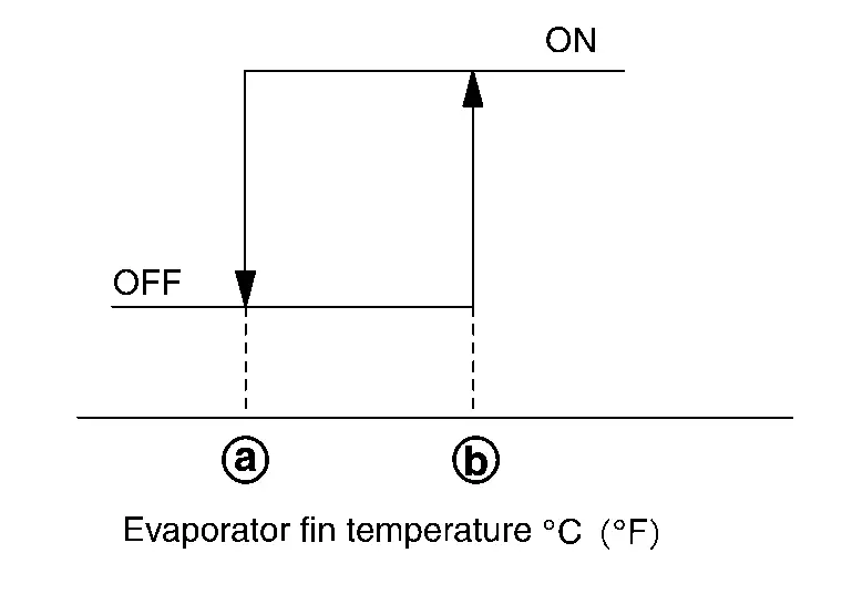
When the air temperature returns to  [28.4ô¯F (ã2.0ô¯C)] or more, the A/C compressor is activated.
Refrigerant Discharge Amount Control
-
A/C amp. transmits the ECV control signal via CAN communication. IPDM E/R transmits the control signal to ECV according to the received ECV control signal.
-
ECV is controlled according to change in the duty ratio of the transmitted control signal.
-
Except when temperature setting is full cold or outlet is DEF, A/C amp. controls the refrigerant discharge amount according to the required cooling capacity.
-
A/C amp. increases the refrigerant discharge amount when evaporator temperature is higher than the target temperature upper limit, and reduces the refrigerant discharge amount when evaporator temperature is at or below the target temperature upper limit.
A/C Compressor Oil Circulation Control
When the engine starts, A/C amp. activates the A/C compressor for a few seconds and circulates the A/C compressor oil once.
CONTROL BY ECM
A/C Compressor Protection Control at Pressure Malfunction
The high-pressure side value that is detected by refrigerant pressure sensor is excessively low or high, ECM requests IPDM E/R to turn Smart FET OFF and stop the A/C compressor.
Air Conditioning Cut Control
When the engine condition is high load, ECM transmit Smart FET OFF request to IPDM E/R, and stops the A/C compressor.
Cooling Fan Operation Request Control
DESCRIPTION
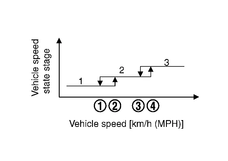
A/C amp. controls the cooling fan operation request according to the refrigerant pressure status and Nissan Ariya vehicle speed status.
NOTE:
For an overview of the cooling fan and information about control. Refer to System Description (Cooling Fan Control System).
CONTROL OUTLINE
-
A/C amp. receives the refrigerant pressure sensor signal from ECM via CAN communication and Nissan Ariya vehicle speed signal from the ABS actuator and electric unit (control unit) via CAN communication.
-
A/C amp. sets one of the optionally determined stages according to the received refrigerant pressure sensor signal and Nissan Ariya vehicle speed signal.
NOTE:
For the rules that prescribe the predetermined stages, refer to the following figures:
-
Nissan Ariya Vehicle speed stages
Vehicle speed [MPH (km/h)]
-
 : 7.5 (12)
 -
 : 12 (20)
 -
 : 45 (72)
 -
 : 50 (80)
-
-
Refrigerant pressure stages
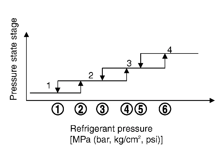
Refrigerant pressure [MPa (bar, kg/cm2, psi)]
-
: 1.28 (12.8, 13.1, 186)
-
: 1.28 (12.8, 13.1, 186)
-
: 1.28 (12.8, 13.1, 186)
-
: 1.28 (12.8, 13.1, 186)
-
 : 1.28 (12.8, 13.1, 186)
 -
 : 1.58 (15.8, 16.1, 229)
-
-
-
The requested cooling fan operation strength (0%, 40%, 100%) is determined according to the combination of these two stages, and the request signal is transmitted to ECM via CAN communication.
Other materials:
P11aa Vcr Position Learning
DTC Description
DTC DETECTION LOGIC DTC
CONSULT screen terms
(Trouble diagnosis content)
DTC detection condition
P11AA
00
VCR position learning
(Variable compression ratio position learning)
Diagnosis condition
Ignition switch ON
Signal (terminal)
ã
Thresho ...
Removal and Installation. Battery Terminal with Fusible Link
Exploded View
Battery terminal with fusible link
: Nôñm (kg-m, in-lb)
: Nôñm (kg-m, ft-lb)
Removal and Installation
REMOVALDisconnect the battery cable from the negative terminal. Refer to Exploded View.
CAUTION:
To prevent damage to the parts, disc ...
U0644 Sent Communication
DTC Description
DTC DETECTION LOGIC DTC No.
CONSULT screen terms
(Trouble diagnosis content) DTC detecting condition
U0644
00
Lost comm with w/g posi sen (b1)
(Lost Communication With Wastegate Position Sensor "A")
Diagnosis condition
Battery voltage: 8 V or more
Igni ...