Nissan Rogue (T33) 2021-Present Service Manual: Diagnosis System (av Control Unit)
Nissanconnect with 8" Color Display
On Board Diagnosis Function
The AV control unit on board diagnosis performs the functions listed in the table below:
DESCRIPTION
| Mode | Description | |
|---|---|---|
| Self Diagnosis |
|
|
| Confirmation/Adjustment | Display Diagnosis |
The following check functions are available:
|
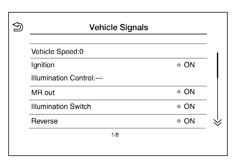
| Nissan Ariya Vehicle Signals | Diagnosis of signals can be performed for Vehicle Speed, Ignition, Illumination Control, MR out, Illumination Switch, Reverse, Parking Brake and ACC. | |
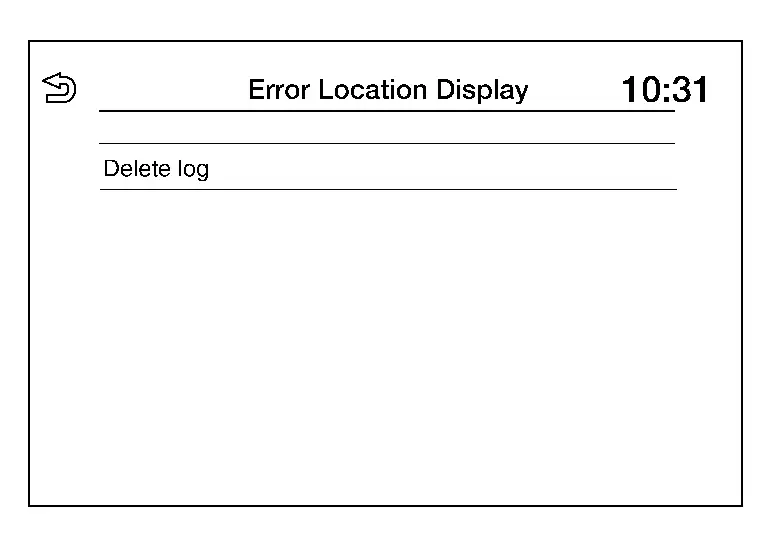
| Error Location Display | The system malfunctions that occurred in the past are displayed. | |
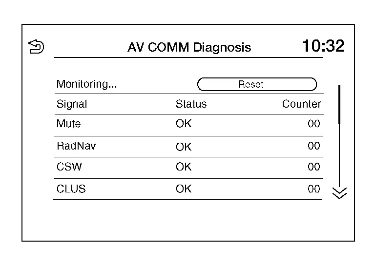
| AV COMM Diagnosis | The AV communication condition of each unit of audio system can be monitored. | |
| Camera |
The following functions are available:
|
|
| Delete Unit Connection Log | Erase the connection history of unit. | |
| Initialize Settings | User Data Initialization is available. | |
| GPS Time set |
This item is displayed but not used. |
|
| Version Information | Version information of the NissanConnect is displayed. | |
| Software Update |
|
|
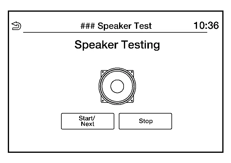
| ### Speaker Test | Individual speakers can be checked at the 100Hz and 4KHz range. | |
| Radio Tuner | FM Monitor and AM Monitor information can be observed. | |
| SXM | Satellite radio monitor information can be observed. | |
Perform CONSULT diagnosis if the AV control unit on board diagnosis does not start, or the screen does not display anything.
METHOD OF STARTING
AV Control Unit Self Diagnosis
-
Turn the ignition switch ON.
-
Turn the audio system OFF.
-
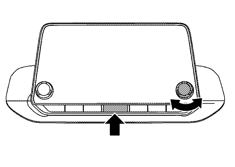
While âMENUâ button is pressed rotate the "TUNE-SCROLL" dial counterclockwise for 3 or more clicks, clockwise for 3 or more clicks, counterclockwise for 3 or more clicks.
-
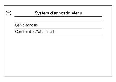
The trouble diagnosis initial screen is displayed, and âSelf Diagnosisâ and âConfirmation/Adjustmentâ can be selected.
SELF-DIAGNOSIS MODE
-
Start the self-diagnosis function and select âSelf Diagnosisâ.
-
Self-diagnosis subdivision screen is displayed, and the self-diagnosis mode starts.
-
The bar graph visible on the center of the self-diagnosis subdivision screen indicates progress of the trouble diagnosis.
-
-
Diagnosis results are displayed after the self-diagnosis is completed. The unit names and the connection lines are color-coded according to the diagnostic results.
Diagnosis results Unit Connection line Normal Green Green Connection malfunction Gray Yellow Unit malfunction Red Green  NOTE:
NOTE:
-
Replace AV control unit if âSelf-Diagnosis did not run because of a control unit malfunctionâ is indicated. The symptom is AV control unit internal error. Refer to Removal and Installation.
-
If multiple errors occur at the same time for a single unit, the screen switch colors are determined according to the following order of priority: red > gray.
-
-
MCAN, Head Unit and VCAN are displayed:
-
Press the MCAN button and the system components connected via AV communication are displayed.
-
Press the Head Unit button and the components connected to the AV control unit are displayed.
-
Press the VCAN button and the system components connected via CAN communication are displayed. Refer to Trouble Diagnosis Flow Chart for CAN communication diagnosis.
-
Detection Range of Self-diagnosis Mode
-
The self-diagnosis mode allows the technician to diagnose the connection in the communication line between AV control unit and each unit and the internal operation of the AV control unit.
-
Because the start condition of diagnosis function is a switch operation, the on board diagnosis function cannot be started up if any malfunction is detected in the AV control unit switches.
SELF-DIAGNOSIS RESULTS
Only Unit Part Is Displayed In Red (MCAN)
| Screen switch | Description | Possible malfunction location / Action to take |
|---|---|---|
| Head Unit | Malfunction is detected in AV control unit power supply and ground circuits. |
Check AV control unit power supply and ground circuits. Refer to Diagnosis Procedure. When no malfunction is detected in those circuits, replace AV control unit. Refer to Removal and Installation. |
| DiagMuxMCAN | Displayed, but not used. | |
| Sep.AMP | ||
| Meter | Malfunction is detected in combination meter power supply and ground circuits. |
Check combination meter power supply and ground circuits. Refer to Diagnosis Procedure. When no malfunction is detected in those circuits, replace combination meter. Refer to . Removal and Installation |
Only Unit Part Is Displayed In Red (Head Unit)
| Screen switch | Description | Possible malfunction location / Action to take |
|---|---|---|
| Head Unit | Malfunction is detected in AV control unit power supply and ground circuits. |
Check AV control unit power supply and ground circuits. Refer to Diagnosis Procedure. When no malfunction is detected in those circuits, replace AV control unit. Refer to Removal and Installation. |
| Amplifier | Malfunction is detected in the internal amplifier of the AV control unit. |
Replace the AV control unit. Refer to Removal and Installation. |
| Antenna | Malfunction is detected in antenna signal circuit. |
Check antenna signal circuit. Refer to Diagnosis Procedure. When no malfunction is detected in the circuit, replace antenna. Refer to Removal and Installation. |
| Speaker | Malfunction is detected in a speaker. |
Perform the ### Speaker Test from the Self Diagnosis procedure. When no malfunction is detected during the Self Diagnosis procedure, replace AV control unit. Refer to Removal and Installation. |
| LVDS | Malfunction is detected in the LVDS harness for the around view monitor control unit. | Replace the LVDS harness. |
| USB |
|
Replace the USB harness. |
| FAN | Malfunction is detected in the internal fan of the AV control unit. |
Replace the AV control unit. Refer to Removal and Installation. |
A Connecting Cable Between Units Is Displayed In Yellow (MCAN)
| Area with yellow connection lines | Description | Possible malfunction location / Action to take |
|---|---|---|
| Head Unit â DiagMuxMCAN | Displayed, but not used. | |
| Head Unit â Sep.AMP | ||
| Head unit â Meter | Combination meter AV communication connection malfunction detected. |
AV communication circuits between AV control unit and combination meter. Refer to Diagnosis Procedure. |
A Connecting Cable Between Units Is Displayed In Yellow (Head Unit)
| Area with yellow connection lines | Description | Possible malfunction location / Action to take |
|---|---|---|
| Head Unit â Amplifier | Internal amplifier malfunction detected. |
Replace the AV control unit. Refer to Removal and Installation. |
| Head Unit â Antenna | Antenna connection malfunction detected. |
Antenna disconnected. Refer to Diagnosis Procedure. |
| Head Unit â Speaker | Speaker connection malfunction detected. |
Speaker disconnected. Refer to the ### Speaker Test from the Self Diagnosis procedure. |
| Head Unit â LVDS | LVDS harness for around view monitor control unit connection malfunction detected. | LVDS harness disconnected. |
| Head unit â USB |
|
USB harness disconnected. |
| Head Unit â FAN | Internal fan malfunction detected. |
Replace the AV control unit. Refer to Removal and Installation. |
CONFIRMATION/ADJUSTMENT MODE
-
Start the diagnosis function and select âConfirmation/Adjustmentâ. The confirmation/adjustment mode indicates where each item can be checked or adjusted.
-
Select each switch on the âConfirmation/Adjustment Modeâ screen to display the relevant trouble diagnosis screen. Touch the âBackâ to return to the initial Confirmation/Adjustment Mode screen.
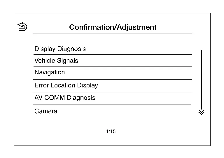
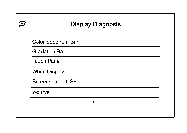
Display Diagnosis
Confirmation of the AV control unit screen operation.
Vehicle Signals
A comparison check can be made of each actual vehicle signal and the signals recognized by the system.
Error Location Display
Results of the error occurrence are represented by the time the error occurred.
AV COMM Diagnosis
AV COMM Monitor
-
Displays the communication status between AV control unit (master unit) and each unit.
-
The error counter displays âOKâ if any malfunction was not detected in the past and displays â0â if a malfunction is detected. It increases by 1 if the condition is normal at the next ignition switch ON cycle. The upper limit of the counter is 39.
-
The error counter is erased if âResetâ is pressed.
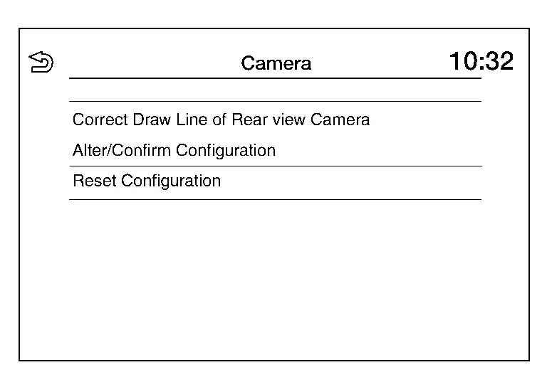
Camera
| Item | Description |
|---|---|
| Correct Draw Line of Rear view Camera | The guiding lines in the rear view monitor can be adjusted. |
| Alter/Confirm Configuration | Displays the current configuration data. |
| Reset Configuration | Initializes the camera system configuration. |
Delete Unit Connection Log
Deletes error records from the AV control unit memory.

Initialize Settings
Initializes the AV control unit memory.
GPS Time Set
NOTE:
This item is displayed but not used.

Version Information
Version information of the components of the Multi AV system are displayed.

Software Update
Version of the AV control unit software can be updated.
### Speaker Test
Two test tones, 100Hz and 4KHz, can be generated to each speaker.
Radio Tuner
Displays FM and AM monitor information.
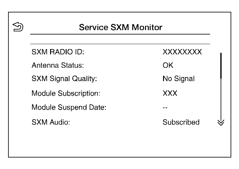
SXM
Displays SXM monitor information.
CONSULT Function
APPLICATION ITEMS
CONSULT performs the following functions via communication with the AV control unit:
| Diagnosis mode | Function |
|---|---|
| Self diagnosis result | The AV control unit self diagnosis results are displayed. |
| ECU identification | The AV control unit part number is displayed. |
| Work supports | Changes setting of each function. |
| Data monitor | The AV control unit input/output data is displayed in real time. |
| Replace ECU | Writes the Nissan Ariya vehicle specification when replacing the AV control unit. |
SELF DIAGNOSIS RESULT
Refer to DTC Index.
Freeze Frame Data (FFD)
The following vehicle status is recorded when DTC is detected and is displayed on CONSULT.
| Item name | Display content |
|---|---|
|
ODO/TRIP METER (km) |
Total driving distance (odometer value) upon DTC detection is displayed. |
| DTC count | Records the number of times DTC was detected. |
ECU IDENTIFICATION
The part number of AV control unit is displayed.
WORK SUPPORTS
| Item | Remarks |
|---|---|
| VIN registration | Allows the writing of the VIN to the AV control unit. |
| Network initial settings | Perform AV control unit communication initialization. |
DATA MONITOR
NOTE:
The table below also includes information (items) that are not applicable to this Nissan Ariya vehicle. Check the display contents of CONSULT for this vehicle adaptation information (item).
| Monitor Item | Unit | Description |
|---|---|---|
| Auto ACC | On/Off |
This item is displayed, but cannot be monitored. |
| ACC | On/Off | Indicates the status of the ACC signal. |
| Aux IN 1 | On/Off | Indicates the connection status of the front USB media module. |
| Parking brake | On/Off | Indicates status of parking brake signal. |
| TCU mute signal | On/Off | Indicates status of mute signal received from TCU. |
| REVERSE SIGNAL | On/Off | Indicates status of the reverse signal. |
| ILLUMINATION SIGNAL | On/Off |
This item is displayed, but cannot be monitored. |
| Sunload sensor | On/Off | Indicates status of Sunload sensor signal received from the A/C amp. |
| IGN SIGNAL | On/Off | Indicates condition of ignition signal. |
| Illumination Control | % |
This item is displayed, but cannot be monitored. |
REPLACE ECU
Writes the vehicle specification when replacing AV control unit.
Other materials:
Removal and Installation. Driver Air Bag Module
Exploded View
1.
Steering wheel
2.
Driver air bag module
Removal and Installation
WARNING:
Always observe the following items for preventing accidental activation.
Before servicing, place the ignition switch in the OFF position,
disconnect main battery negat ...
Direction assistÃĐe ÃĐlectrique
AVERTISSEMENT
Lorsque le moteur est arrÊtÃĐ, la direction assistÃĐe ÃĐlectrique ne fonctionne plus et un effort accru est nÃĐcessaire pour tourner le volant.
Si le systÃĻme de direction assistÃĐe ÃĐlectrique se dÃĐsactive pendant la conduite, le tÃĐmoin d'avertissement correspondant s'allume. ...
U2141 Can Comm Circuit
DTC Description
DTC DETECTION LOGIC DTC
CONSULT screen terms
(Trouble diagnosis content)
DTC detection condition
U2141
57
CAN comm err (TCM)
[CAN comm err (TCM)]
Diagnosis condition
Ignition switch ON
Signal (terminal)
CAN communication signal
Threshold
MA ...