Nissan Rogue (T33) 2021-Present Service Manual: Type B :: Removal and Installation
Combination Meter
Exploded View
REMOVAL
Refer to Exploded View.
DISASSEMBLY
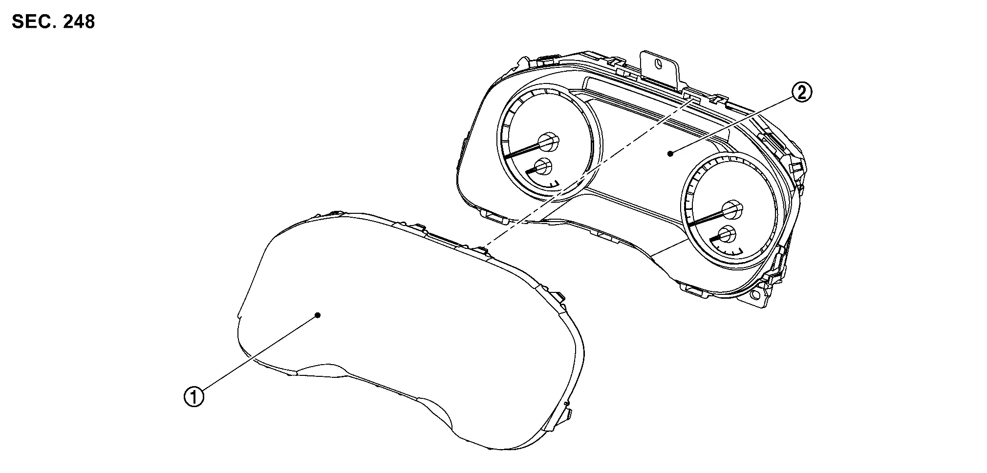
 |
Front cover |  |
Meter control unit |
Removal and Installation
CAUTION:
-
When replacing the combination meter, always replace it with a new one. The functions controlled by the combination meter does not operate properly in case of reuse of the combination meter from another Nissan Ariya vehicle.
-
Be sure to perform the configuration when replacing combination meter. Refer to Work Procedure.
REMOVAL
 NOTE:
NOTE:
Do not swap combination meter modules between Nissan Ariya vehicles for any reason.
Disconnect the battery cable from the negative terminal.
Remove cluster lid A. Refer to Removal and Installation.
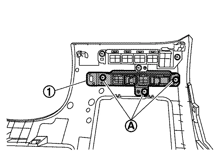
Remove the mounting screws  of the combination meter .
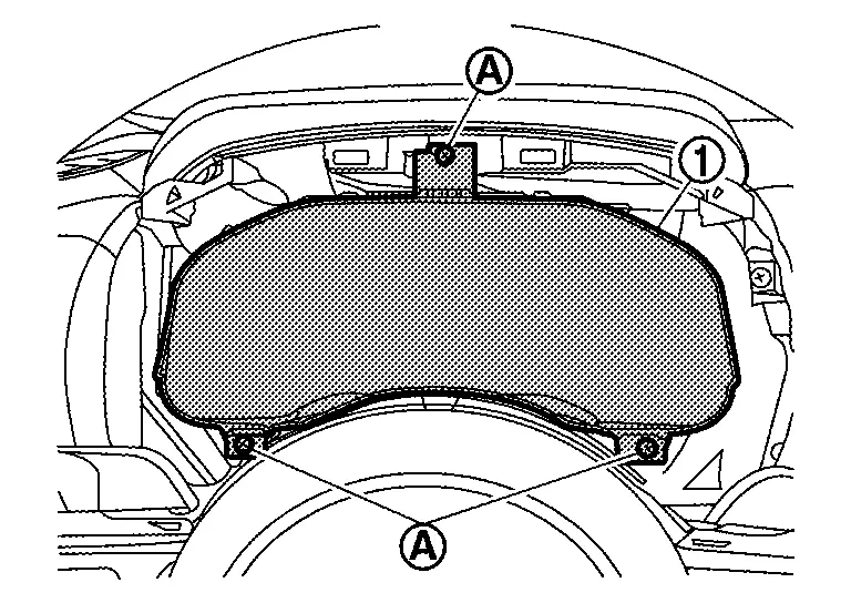
Pull the combination meter outward, then disconnect harness connector and remove.
CAUTION:
Never damage the front cover.
INSTALLATION
Installation is in the reverse order of removal.
CAUTION:
-
Never damage the front cover.
-
When replacing the combination meter, always replace it with a new one. The functions controlled by the combination meter does not operate properly in case of reuse of the combination meter from another Nissan Ariya vehicle.
-
Be sure to perform the configuration when replacing combination meter. Refer to Work Procedure.
NOTE:
Do not swap combination meter modules between Nissan Ariya vehicles for any reason.
Disassembly and Assembly
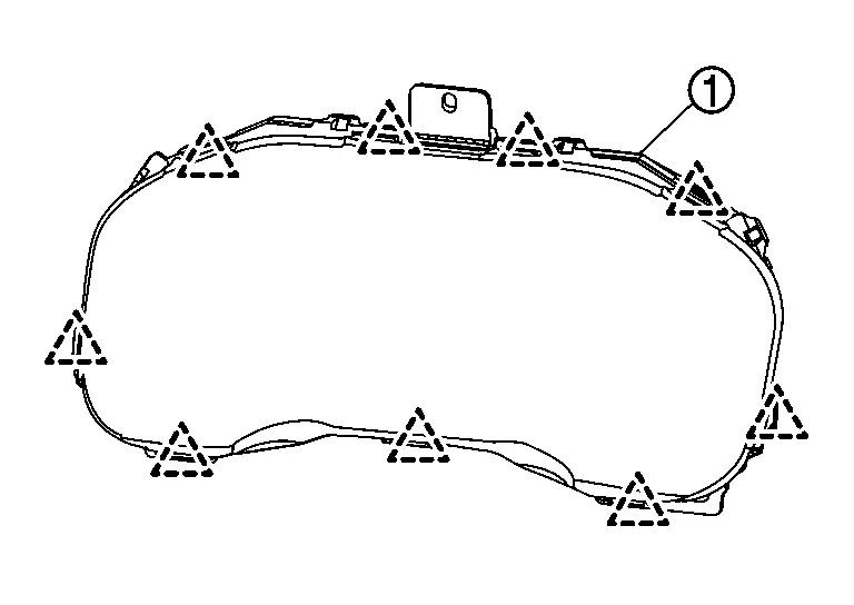
DISASSEMBLY
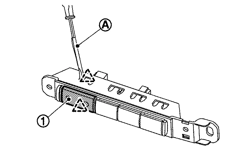
Disengage the pawls of combination meter to allow the front cover  to become slightly released.
CAUTION:
Never damage the front cover.
 |
: Pawl |
Pull the front cover straight to remove it from the meter control unit.
CAUTION:
-
Never damage the front cover.
-
Never touch the inside of front cover, pointer, the display and the printed area of the dial during the work.
-
Keep away from magnetic sources.
ASSEMBLY
Install the front cover straight to the unified meter control unit and engage all the pawl.
CAUTION:
-
Never damage the front cover.
-
Never touch the inside of front cover, pointer, the display and the printed area of the dial during the work.
-
Keep away from magnetic sources.
Meter Speaker
Removal and Installation
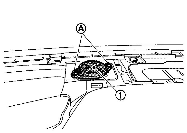
REMOVAL
Remove instrument garnish. Refer to Removal and Installation.
Remove the meter speaker mounting screws, and remove the meter speaker .
INSTALLATION
Install in the reverse order of removal.
Illumination Control Switch
Removal and Installation
REMOVAL
Remove the instrument lower panel LH. Refer to Removal and Installation.
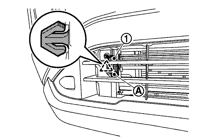
Remove screws to remove switch bracket .
Disengage fixing pawl with removal tool to remove illumination control switch from switch bracket.
|
:Pawl |
INSTALLATION
Install in the reverse order of removal.
Steering Switches
Removal and Installation
REMOVAL
Refer to Removal and Installation.
NOTE:
Always remove steering switch together with steering wheel.
INSTALLATION
Installation is in the reverse order of removal.
Ambient Sensor
Removal and Installation
REMOVAL
Disengage fixing pawl.
|
: Pawl |
Disconnect harness connector to remove ambient sensor .
INSTALLATION
Install in the reverse order of removal.
Oil Level Sensor
Removal and Installation
REMOVAL
Refer to Exploded View.
INSTALLATION
Install in the reverse order of removal.
Other materials:
B20e2-96 Led Headlamp Rh
DTC Description
DTC DETECTION LOGIC DTC No.
CONSULT screen items
(Trouble diagnosis content) DTC detection condition
B20E2–96
LED HEADLAMP RH
(Light emitting diode headlamp right hand)
[CMPNENT INTERNAL MLFNCTN]
Diagnosis condition
Ignition switch ON
Signal (terminal)
...
Basic Inspection. Diagnosis and Repair Work Flow
Work Flow
OVERALL SEQUENCEDETAILED FLOWGET INFORMATION FOR SYMPTOM
Get detailed information from the customer about the symptom (the
condition and the environment when the incident/malfunction occurs).
Check operation condition of the function that is malfunctioning.
>>
G ...
Symptom Diagnosis. Intelligent Key Interlock Function Does Not Operate
Diagnosis Procedure
CHECK VEHICLE SPECIFICATION
Check if vehicle equipped navigation system.
Is equipped navigation system?
YES>>
GO TO 2.
NO>>
GO TO 3.
CHECK LOG-IN FUNCTION
Check log-in function. Refer to System Description.
Is the inspection result normal?
YES>>
G ...