Nissan Rogue (T33) 2021-Present Service Manual: Driver Information & Multimedia :: Warning Chime System
How to Use This Manual :: Application Notice
Information
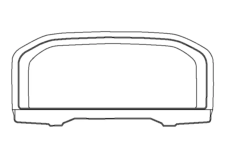
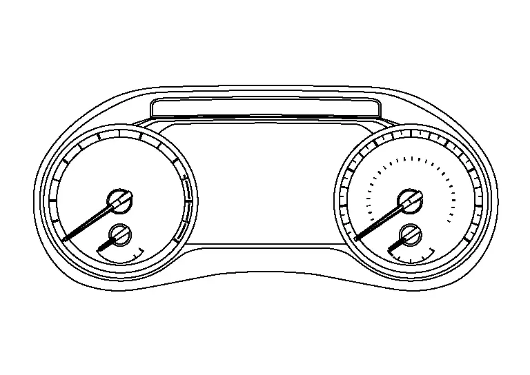
| Service information | Design of combination meter |
|---|---|
| TYPE A |
|
| TYPE B |
|
Precaution :: Precautions
Precaution for Supplemental Restraint System (SRS) "AIR BAG" and "SEAT BELT PRE-TENSIONER"
The Supplemental Restraint System such as “AIR BAG” and “SEAT BELT PRE-TENSIONER”, used along with a front seat belt, helps to reduce the risk or severity of injury to the driver and front passenger for certain types of collisions.
Information necessary to service the system safely is included in the “SRS AIR BAG” and “SEAT BELT” sections of this Service Manual.
WARNING:
Always observe the following items for preventing accidental activation:
-
To avoid rendering the SRS inoperative, which could increase the risk of personal injury or death in the event of a collision that would result in air bag inflation, it is recommended that all maintenance and repair be performed by an authorized NISSAN/INFINITI dealer.
-
Improper repair, including incorrect removal and installation of the SRS, can lead to personal injury caused by unintentional activation of the system. For removal of Spiral Cable and Air Bag Module, see “SRS AIR BAG”.
-
Never use electrical test equipment on any circuit related to the SRS unless instructed to in this Service Manual. SRS wiring harnesses can be identified by yellow and/or orange harnesses or harness connectors.
PRECAUTIONS WHEN USING POWER TOOLS (AIR OR ELECTRIC) AND HAMMERS
WARNING:
Always observe the following items for preventing accidental activation:
-
When working near the Air Bag Diagnosis Sensor Unit or other Air Bag System sensors with the ignition/power switch ON or engine running, never use air or electric power tools or strike near the sensor(s) with a hammer. Heavy vibration could activate the sensor(s) and deploy the air bag(s), possibly causing serious injury.
-
When using air or electric power tools or hammers, always switch the ignition/power switch OFF, disconnect the 12V battery or batteries, and wait at least 3 minutes before performing any service.
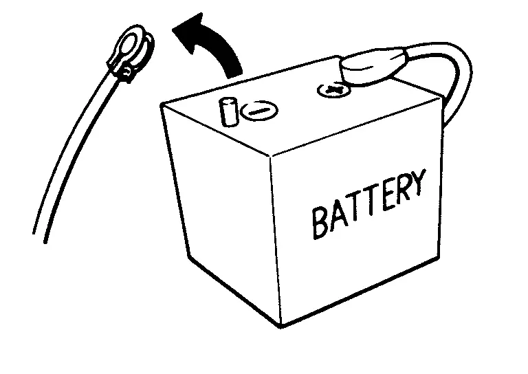
Precautions for Removing Battery Terminal
-
With the adoption of Auto ACC function, ACC power is automatically supplied by operating the Intelligent Key or remote keyless entry or by opening/closing the driver side door. In addition, ACC power is supplied even after the ignition switch is turned to the OFF position, i.e. ACC power is supplied for a certain fixed time.
-
When disconnecting the 12V battery terminal, turn off the ACC power before disconnecting the 12V battery terminal, observing “How to disconnect 12V battery terminal” described below.
 NOTE:
NOTE:
Some ECUs operate for a certain fixed time even after ignition switch is turned OFF and ignition power supply is stopped. If the battery terminal is disconnected before ECU stops, accidental DTC detection or ECU data damage may occur.
-
For Nissan Ariya vehicles with the 2-batteries, be sure to connect the main battery and the sub battery before turning ON the ignition switch.
NOTE:
If the ignition switch is turned ON with any one of the terminals of main battery and sub battery disconnected, then DTC may be detected.
-
After installing the 12V battery, always check "Self Diagnosis Result" of all ECUs and erase DTC.
NOTE:
The removal of 12V battery may cause a DTC detection error.
HOW TO DISCONNECT 12V BATTERY TERMINAL
Disconnect 12V battery terminal according to instruction described below.
-
Open the hood.
-
Turn ignition switch to the ON position.
-
Turn ignition switch to the OFF position with the driver side door opened.
-
Get out of the Nissan Ariya vehicle and close the driver side door.
-
Wait at least 3 minutes.
CAUTION:
While waiting, never operate the Nissan Ariya vehicle such as locking, opening, and closing doors. Violation of this caution results in the activation of ACC power supply according to the Auto ACC function.
-
Remove 12V battery terminal.
CAUTION:
After installing 12V battery, always check self-diagnosis results of all ECUs and erase DTC.
System Description :: Component Parts. Warning Chime System
Warning Chime System
Component Parts Location
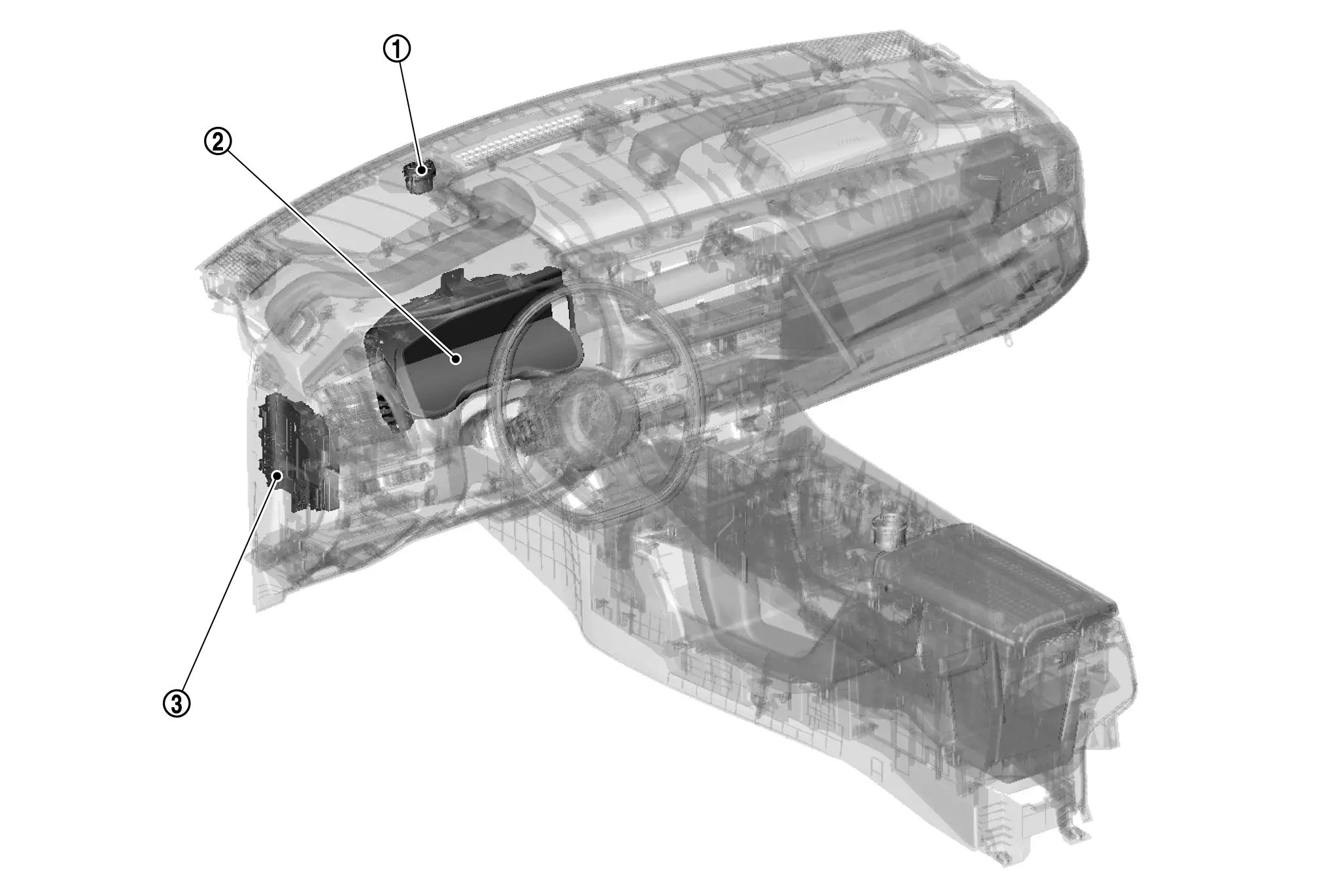
| NO | Component | Function |
|---|---|---|
| 1. | Meter speaker | Refer to Meter Speaker. |
| 2. | Combination Meter | Refer to Combination Meter. |
| 3. | BCM (Body Control Module) |
Based on the signals received from various units and switches, transmits the buzzer output signal to the combination meter via CAN communication. Refer to Component Parts Location for detailed component location. |
Combination Meter
The combination meter transmits the following warnings to the meter speaker when receiving the buzzer output signal transmitted from each unit.
Type A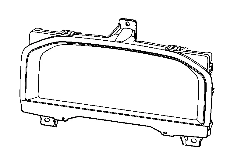
Type B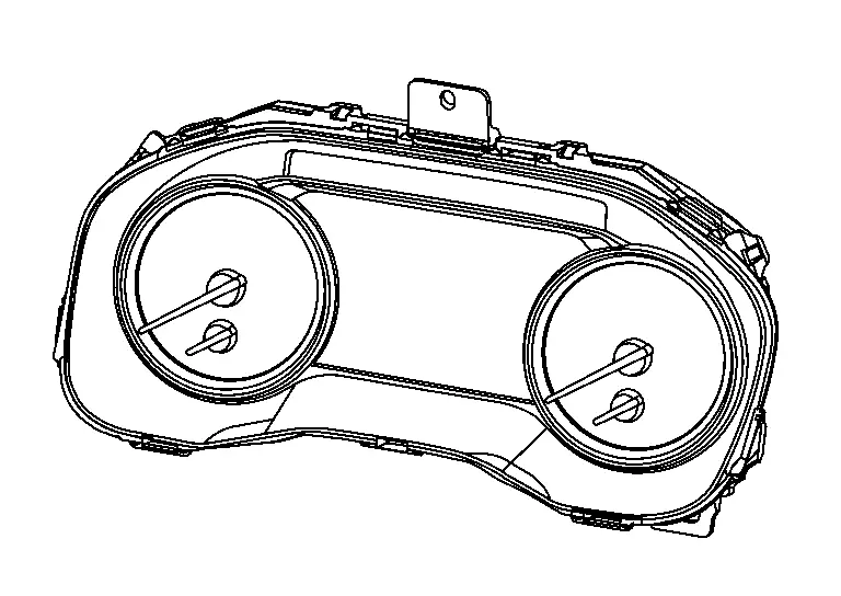
-
Door lock operation warning
-
Electric shift warning
-
Light reminder warning
-
Seat belt warning
-
Shift position warning
-
Shift P warning
-
Take away warning
Meter Speaker
Component Function Within The System
-
Output warning sound by meter speaker signal from combination meter.
Individual Component Function
Sound signals generated by the combination meter output sounds.
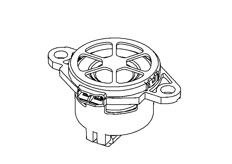
| Size | (Φ) | 1.8 in (4.6 cm) |
| Rated input | (W) | 1.5 |
| MAX input | (W) | 3 |
| Impedance | (Ω) | 8 |
Component Operation
Meter speaker signals are input to the speaker, and sound is output.
Component Parts Location
-
The meter speaker is located on the instrument panel. Refer to Component Parts Location.
System Description :: System
Warning Chime System
System Description
DESCRIPTION
Combination Meter
The combination meter transmits a meter speaker signal to the meter speaker when receiving the buzzer output signal transmitted from each unit.
Meter Speaker
The meter speaker sounds the alarm buzzer when receiving the meter speaker signal from combination meter.
BCM
BCM receives signals from various units and transmits a buzzer output signal to the combination meter via CAN communication if it judges that the warning buzzer should be activated.
WARNING CHIME FUNCTION LIST
| Warning functions | Reference |
|---|---|
| Door lock operation warning | Door Lock Operation Warning |
| Electric shift warning (buzzer) | Electric Shift Warning (Buzzer) |
| Light reminder warning (buzzer) | Light Reminder Warning (Buzzer) |
| Seat belt warning | Seat Belt Warning |
| Shift position warning (buzzer) | Shift Position Warning (Buzzer) |
| Shift P warning (buzzer) | Shift P Warning (Buzzer) |
| Take away warning (buzzer) | Take Away Warning (Buzzer) |
Fail-Safe
The combination meter activates the fail-safe control if CAN communication with each unit is malfunctioning.
| Function | Specifications | |
|---|---|---|
| Buzzer | The buzzer turns OFF by suspending communication. | |
Warning Chime
Door Lock Operation Warning
PURPOSE
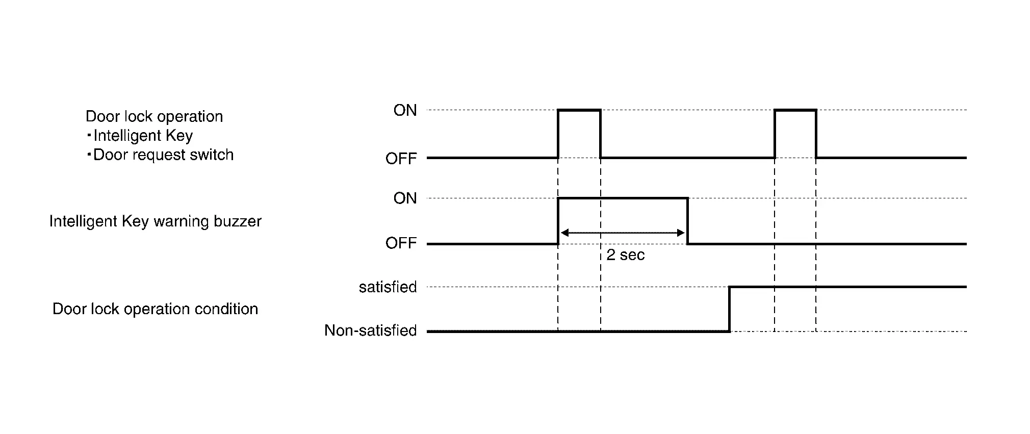
Door lock operation warning warns the driver that door cannot be locked because of inappropriate operation, when door lock operation using Intelligent Key button operation or door request switch is not performed normally.
SYSTEM DIAGRAM
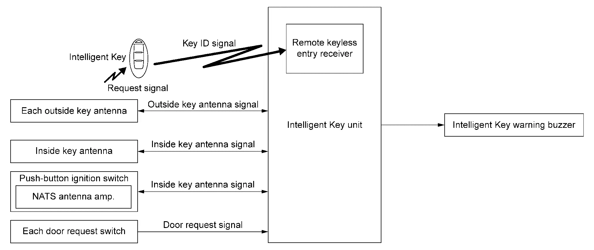
SIGNAL PATH
-
Intelligent Key unit judges whether or not warning the driver is required, according to each switch signal, inside key antenna signal and outside key antenna signal.
-
When Intelligent Key unit judges that warning the driver is required, Intelligent Key warning buzzer operates.
WARNING OPERATING CONDITION
All doors do not lock using Intelligent Key or each door request switch.
-
Intelligent Key operation condition
Refer to System Description.
-
Door request switch operation condition
Refer to System Description.
WARNING CANCEL CONDITION
When any of the following conditions are satisfied.
-
2 seconds are passed.
-
All doors are locked or unlocked by Intelligent Key or each door request switch.
TIMING CHART
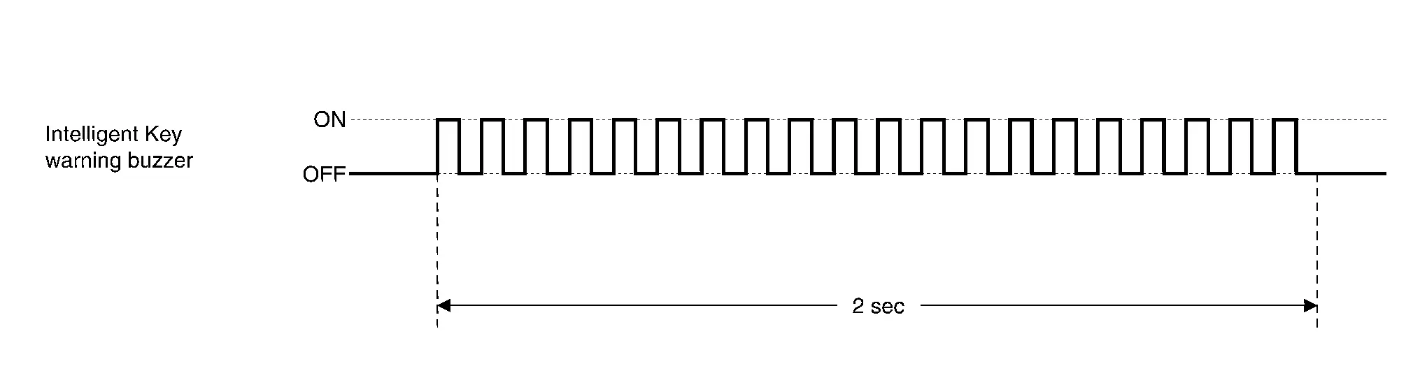
SOUND SPECIFICATION
Electric Shift Warning (Buzzer)
PURPOSE
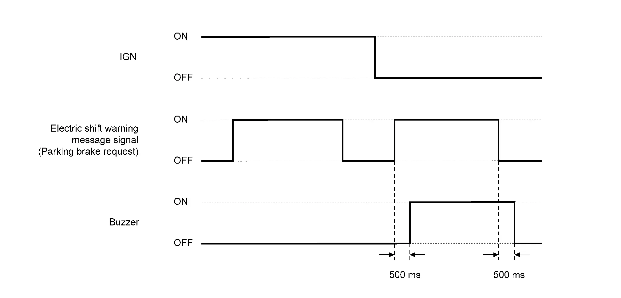
The electric shift warning warns the driver to apply the parking brake when the transmission does not shift to P position due to electric shift system malfunction.
SYNCHRONIZATION WITH WARNING/INDICATOR (INFORMATION DISPLAY)
For warning/indicator (information display). Refer to Electric Shift Warning.
OPERATION AT COMBINATION METER CAN COMMUNICATION CUT-OFF OR UNUSUAL SIGNAL
For actions on CAN communications blackout in the combination meter, refer to Fail-Safe.
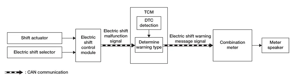
SYSTEM DIAGRAM
SIGNAL PATH
-
The electric shift control module transmits an electric shift malfunction signal to the TCM when detecting a malfunction in the electric shift system.
-
TCM detects DTC when TCM receives an electric shift malfunction signal.
-
TCM transmits an electric shift warning message signal to the combination meter when detecting DTC in TCM.
-
The combination meter sounds an electric shift warning buzzer according to the electric shift warning message signal.
WARNING OPERATING CONDITION
When all of the following conditions are satisfied:
-
Ignition switch OFF
-
Parking brake is not applied
-
When electric shift system detects DTC of master warning lamp (red)
WARNING CANCEL CONDITION
When any of the conditions listed below is satisfied:
-
Ignition switch ON
-
Apply the parking brake while the ignition switch ON, then place the ignition switch OFF.
-
Erase DTC
SOUND SPECIFICATION
Light Reminder Warning (Buzzer)
PURPOSE
Light reminder warning warns the driver of egression from the vehicle while engine status is other than running and lamp is in ON status.
SYNCHRONIZATION WITH WARNING/INDICATOR (INFORMATION DISPLAY)
For warning/indicator (information display). Refer to Light Reminder Warning (Information Display).
OPERATION AT COMBINATION METER CAN COMMUNICATION CUT-OFF OR UNUSUAL SIGNAL
For actions on CAN communications blackout in the combination meter. Refer to Fail-Safe.
SYSTEM DIAGRAM
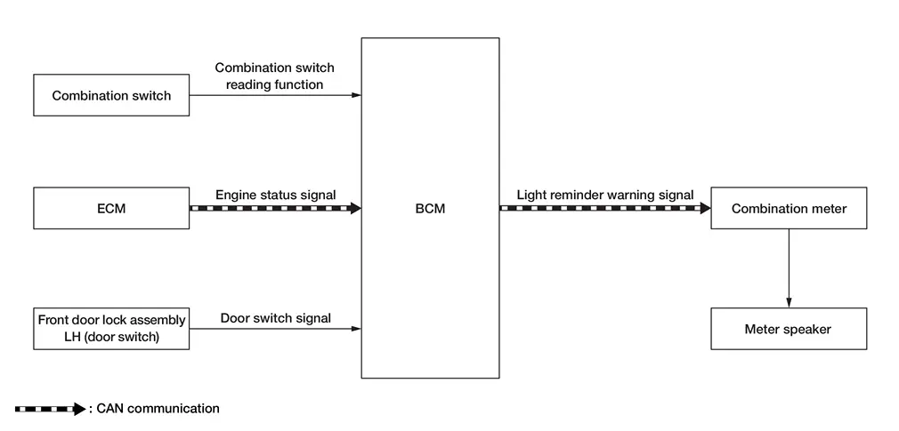
SIGNAL PATH
-
BCM reads status of combination switch.
-
BCM detects vehicle condition depending on the engine status signal (received from ECM via CAN communication).
-
BCM judges light reminder warning by lighting switch signal, front door switch (driver side) signal and engine status signal. BCM transmits light reminder warning signal to combination meter via CAN communication.
-
When combination meter receives light reminder warning signal, and output the buzzer signal to meter speaker.
-
Meter speaker sounds warning buzzer according buzzer signal from combination meter.
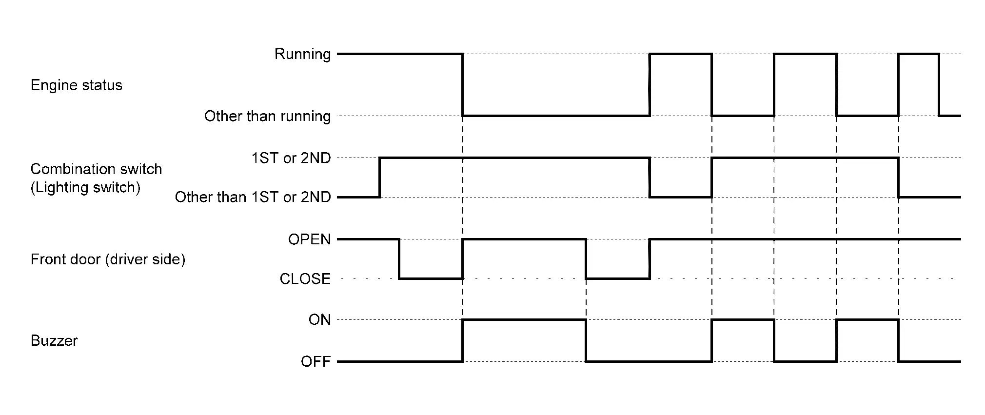
WARNING OPERATING CONDITION
When all of the following conditions are satisfied.
-
Engine status is other than running
-
Lighting switch 1ST or 2ND
-
Front door (driver side) OPEN [front door switch (driver side) ON]
WARNING CANCEL CONDITION
When any of the following conditions are satisfied.
-
Engine status is running
-
Lighting switch other than 1ST or 2ND
-
Front door (driver side) CLOSE [front door switch (driver side) OFF]
TIMING CHART
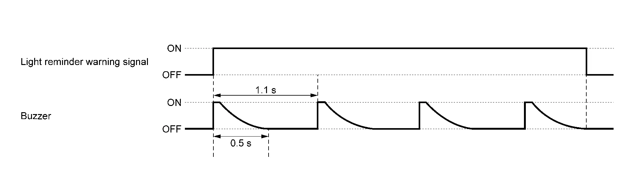
SOUND SPECIFICATION
Seat Belt Warning
DESCRIPTION
Seat belt warning lamp warns the driver that front seat belt LH or front seat belt RH is not fastened.
SYNCHRONIZATION WITH WARNING LAMP/INDICATOR LAMP
For warning lamp, refer to Seat Belt Warning Lamp (Type A meter models) or Seat Belt Warning Lamp (Type B meter models).
SYSTEM DIAGRAM
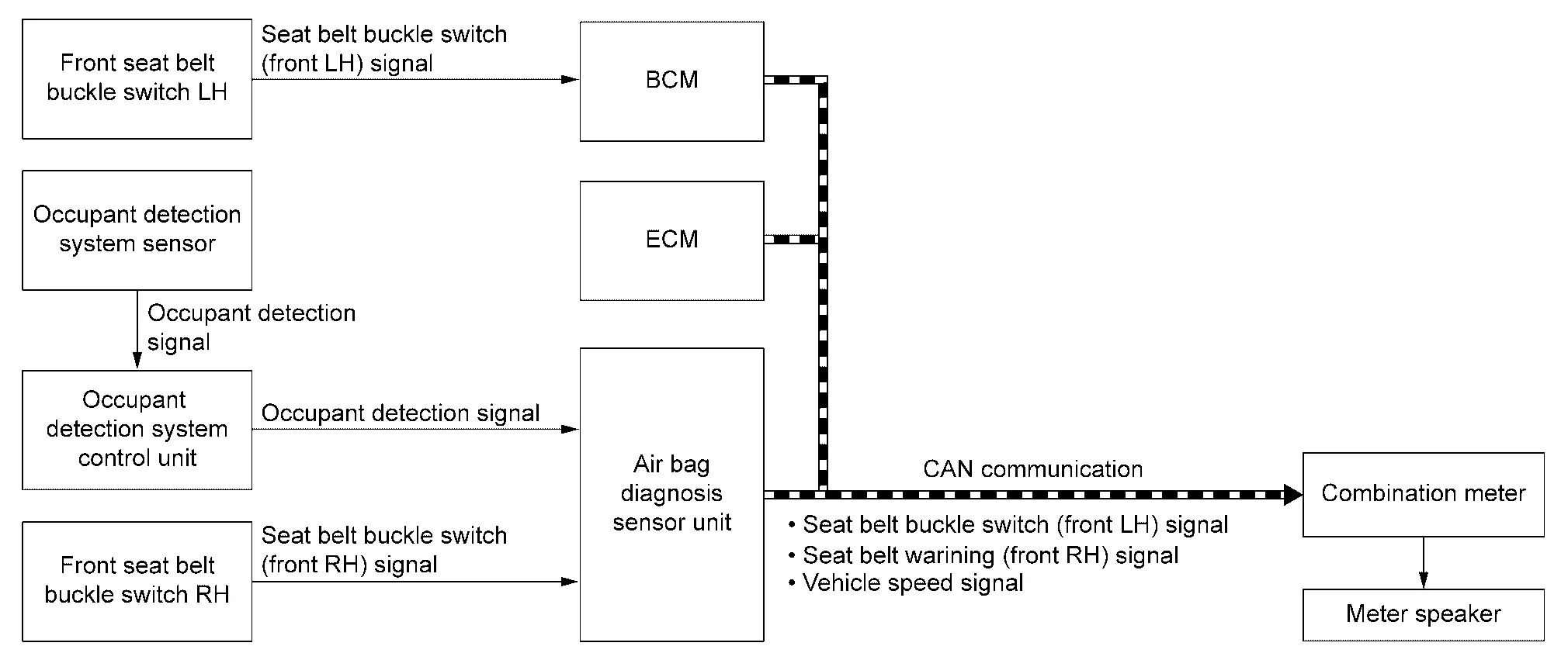
SIGNAL PATH
Combination meter sounds seat belt warning according to seat belt buckle switch (front LH) signal or seat belt warning (front RH) signal.
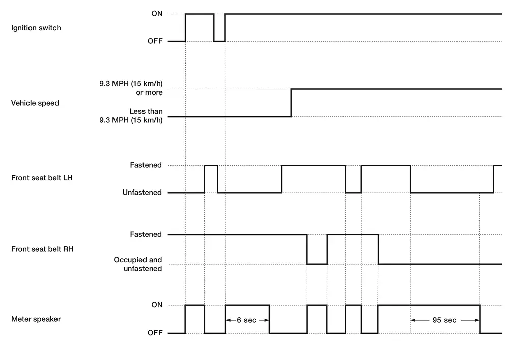
WARNING OPERATION CONDITIONS
Vehicle speed is less than 9.3 MPH (15 km/h)
Combination meter operates seat belt warning buzzer when all of the following conditions are satisfied.
-
Ignition switch is ON.
-
Front seat belt LH is not fastened.
Vehicle speed is 9.3 MPH (15 km/h) or more
Combination meter operates seat belt warning buzzer when all of the following conditions are satisfied.
-
Ignition switch is ON.
-
Vehicle speed is 9.3 MPH (15 km/h) or more.
-
When any of the conditions listed below are satisfied.
-
Front seat belt LH is unfastened.
-
Front seat belt RH is unfastened and person sit in the front seat RH.
-
WARNING CANCEL CONDITIONS
Vehicle speed is less than 9.3 MPH (15 km/h)
Combination meter cancels seat belt warning buzzer when any of the following conditions are satisfied.
-
Ignition switch is OFF.
-
Front seat belt LH is fastened.
-
Approximately 6 seconds are passed since warning start.
Vehicle speed is 9.3 MPH (15 km/h) or more
Combination meter cancels seat belt warning buzzer when any of the following conditions are satisfied.
-
Ignition switch is OFF.
-
When any of the conditions listed below are satisfied.
-
Front seat belt LH is fastened.
-
Front seat belt RH is fastened or person does not sit in the front seat RH.
-
-
Approximately 95 seconds are passed since warning start.*
*: Seat belt warning buzzer is cancelled when all of the following conditions are satisfied before approximately 95 seconds elapses.
-
Vehicle speed is less than 1.8 MPH (3 km/h).
-
Shift position is P or parking brake ON
TIMING CHART
SOUND SPECIFICATION
Vehicle speed is less than 9.3 MPH (15 km/h)

Vehicle speed is 9.3 MPH (15 km/h) or more

Shift Position Warning (Buzzer)
PURPOSE
The shift position warning (buzzer) warns the driver that the sift position does not change to the selected position.
SYSTEM DIAGRAM
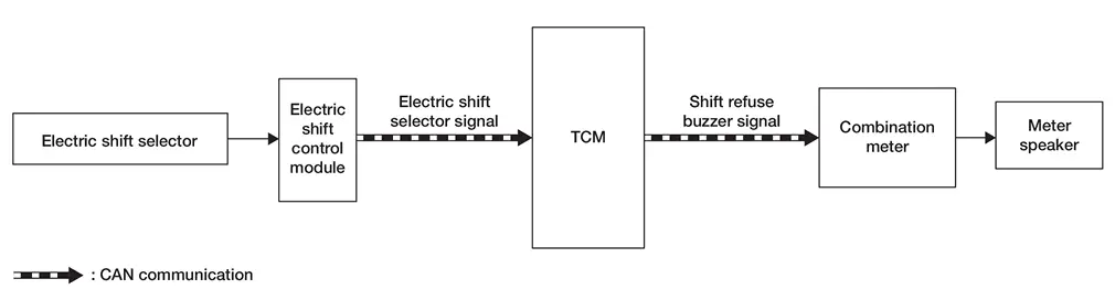
SIGNAL PATH
-
Electric shift control module judges that the shift position can be switched according to a signal transmitted from the electric shift selector.
-
Electric shift control module transmits electric shift selector signal to TCM.
-
When TCM judges that the shift position cannot be switched, TCM transmits a shift refuse buzzer signal to the combination meter.
-
The combination meter sounds a shift position warning according to the shift refuse buzzer signal.
WARNING OPERATING CONDITION
When any of the following conditions are satisfied.
-
When shifted from P position to other position without depressing the brake pedal while the ignition switch is ON.
-
When operating the P position switch while driving at 3 MPH (5 km/h) or more.
-
When the selector lever shifted to R position while driving in D position.
-
When the selector lever shifted to D position while driving in R position.
-
When shifted to P / R / Nr / Nd / D position during protection control (Refer to Protection Control).
-
When shifted to D / R position during the ignition switch ON (engine stopped).
-
When shifted to other position before the previous shift change is completed.
WARNING CANCEL CONDITION
When falling outside the warning operating conditions.
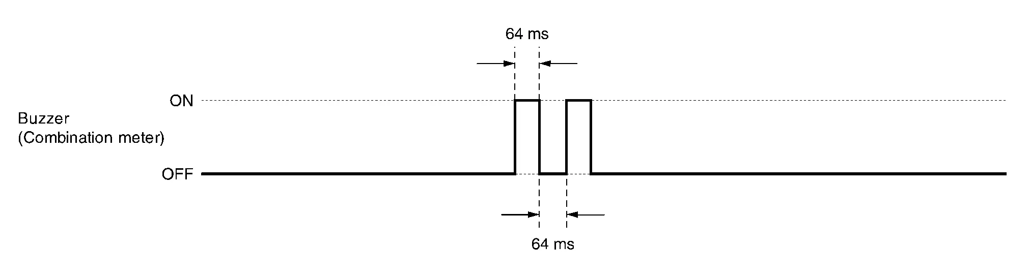
SOUND SPECIFICATION
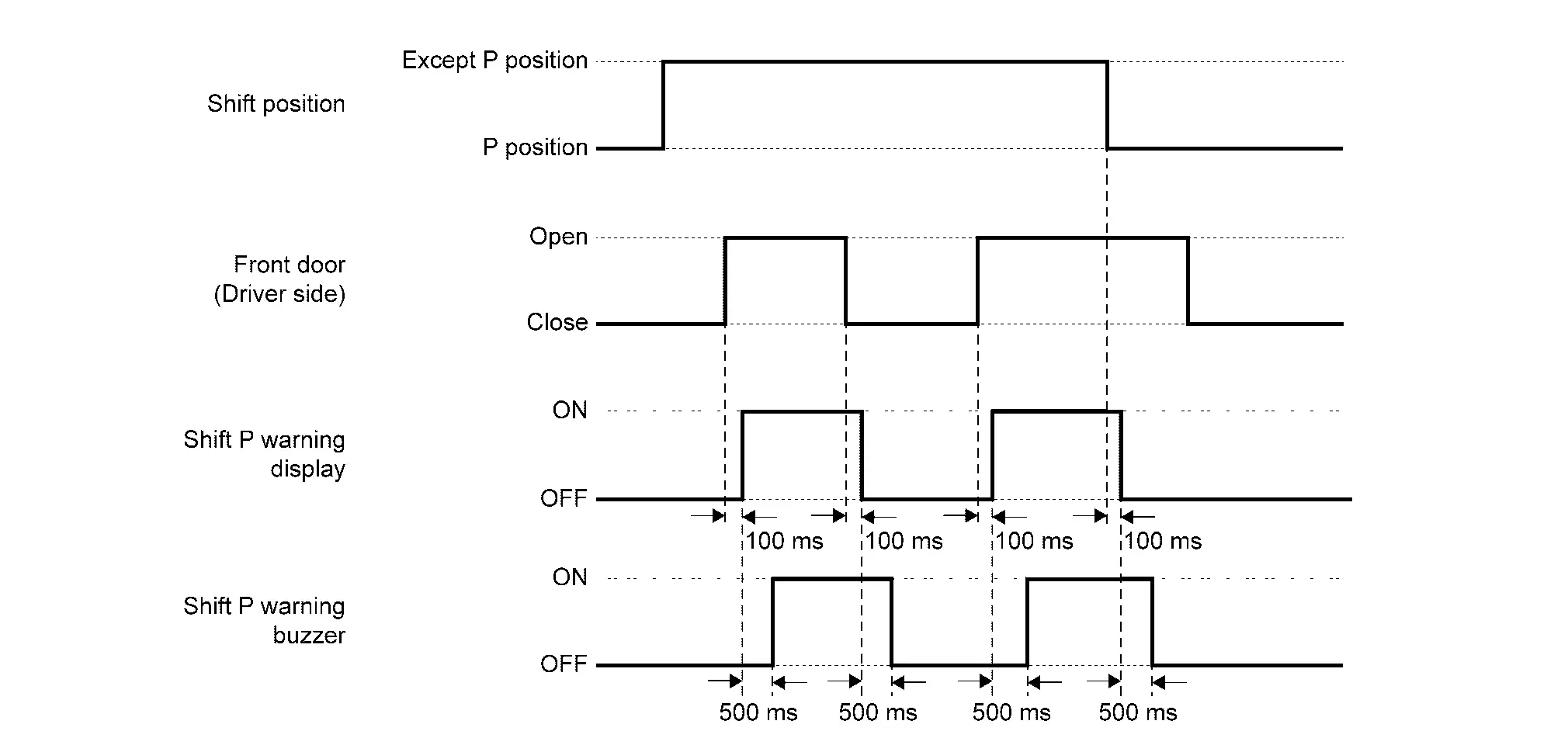
Shift P Warning (Buzzer)
PURPOSE
The shift P warning (buzzer) warns that the drive is getting off the vehicle with the shift position not in P position.
SYNCHRONIZATION WITH WARNING LAMP/INDICATOR LAMP
Not applicable
SYNCHRONIZATION WITH WARNING/INDICATOR (INFORMATION DISPLAY)
Synchronization is applied.
For information display, refer to Shift P Warning.
SYSTEM DIAGRAM
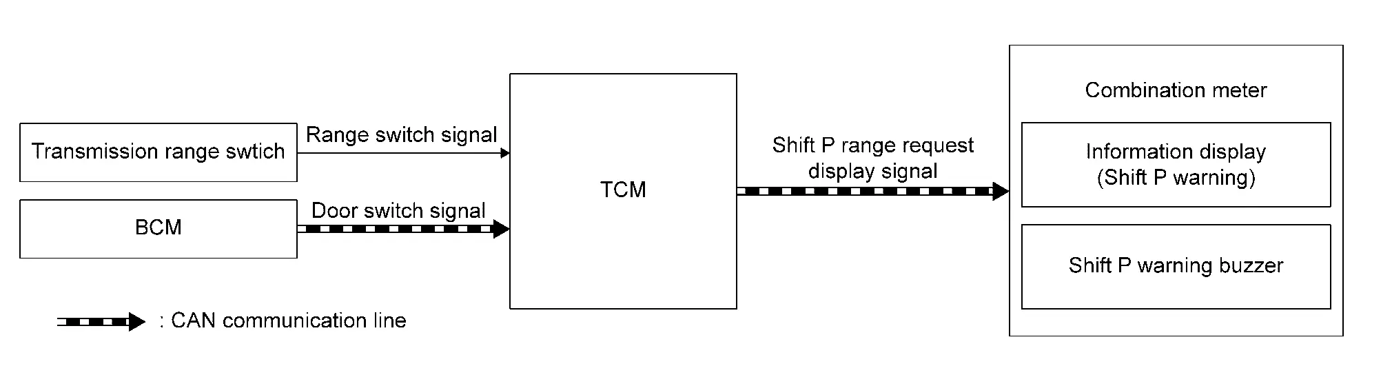
SIGNAL PATH
-
TCM judges the shift position by transmission range switch.
-
BCM transmits a door switch signal to the TCM.
-
The TCM judges the Nissan Ariya vehicle condition according to the shift position signal and the door switch signal. The TCM transmits a shift P range request display signal to the combination meter if the driver’s door is opened with the shift position not in P position.
WARNING OPERATING CONDITION
When all of the following conditions are satisfied:
-
Shift position: P position
-
Front door (driver side): Close
WARNING CANCEL CONDITION
When any of the following conditions are satisfied:
-
The shift position is changed to P position.
-
The driver’s door is closed.
TIMING CHART
Take Away Warning (Buzzer)
PURPOSE
Take away warning warns the driver that Intelligent Key is removed from passenger room, according to the Nissan Ariya vehicle status.
SYNCHRONIZATION WITH WARNING/INDICATOR (INFORMATION DISPLAY)
Synchronization is applied.
Refer to Take Away Warning (Information Display).
SYSTEM DIAGRAM
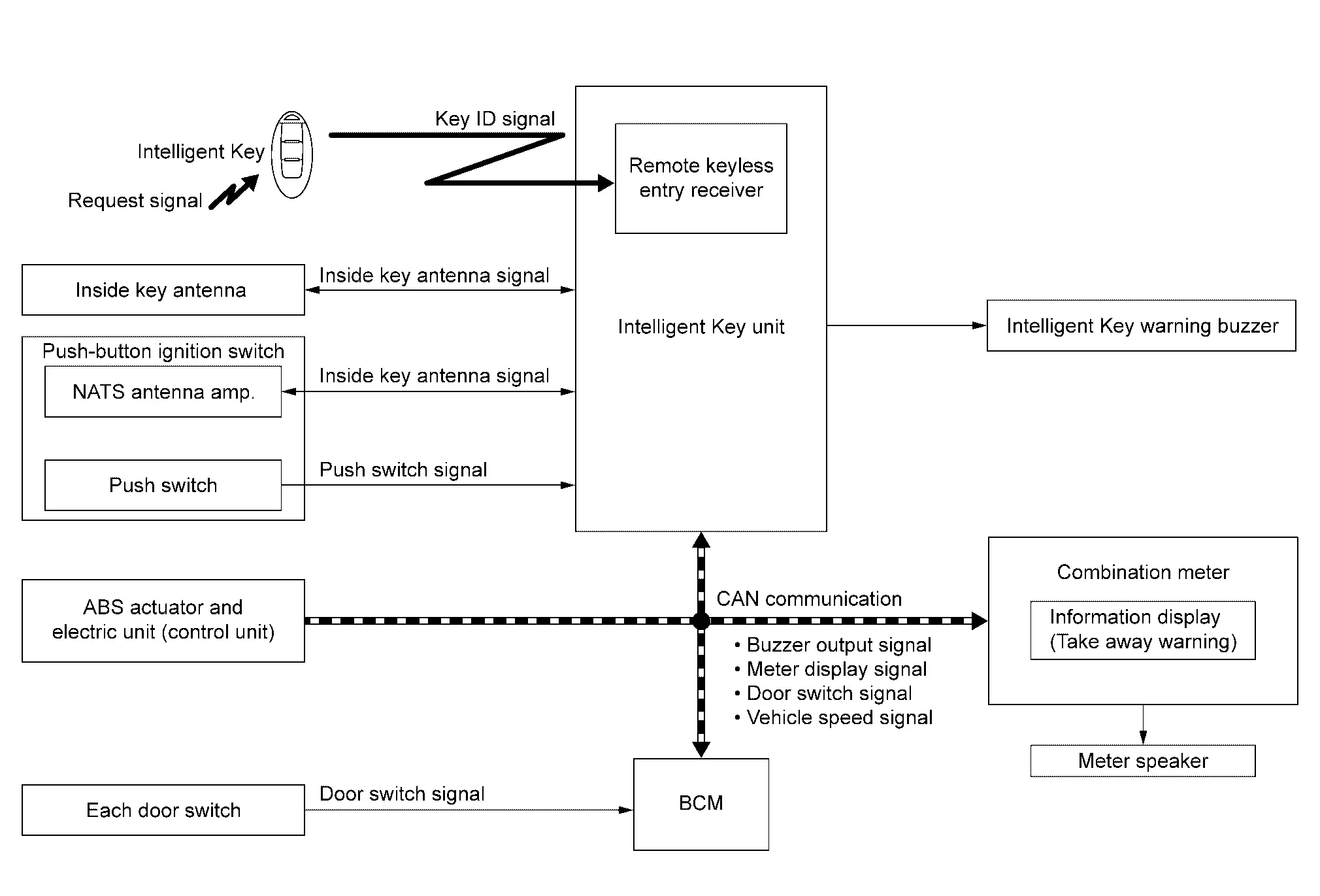
SIGNAL PATH
Door status changes from open to close
-
Intelligent Key unit judges whether or not warning the driver is required, according to push switch signal from push-button ignition switch, door switch signal from each door switch, and inside key antenna signal from inside key antenna and NATS antenna amp.
-
When Intelligent Key unit judges that warning the driver is required, buzzer output signal and meter display signal are transmitted by Intelligent Key unit to combination meter via CAN communication.
-
Combination meter, when it receives buzzer output signal and meter display signal, operates meter speaker and information display. Intelligent Key unit simultaneously operates Intelligent Key warning buzzer.
Push-button ignition switch is pressed
-
Intelligent Key unit judges whether or not warning the driver is required, according to push switch signal from push-button ignition switch, door switch signal from each door switch, and inside key antenna signal from inside key antenna and NATS antenna amp.
-
When Intelligent Key unit judges that warning the driver is required, buzzer output signal and meter display signal are transmitted by Intelligent Key unit to combination meter via CAN communication.
-
Combination meter, when it receives buzzer output signal and meter display signal, operates meter speaker and information display.
When vehicle speed 9.3 MPH (15 km/h)
-
Intelligent Key unit judges whether or not warning the driver is required, according to push switch signal from push-button ignition switch, Nissan Ariya vehicle speed signal from ABS actuator and electric unit (control unit), and inside key antenna signal from each inside key antenna and NATS antenna amp.
-
When Intelligent Key unit judges that warning the driver is required, buzzer output signal and meter display signal are transmitted by Intelligent Key unit to combination meter via CAN communication.
-
Combination meter, when it receives buzzer output signal and meter display signal, operates meter speaker and information display.
WARNING OPERATING CONDITION
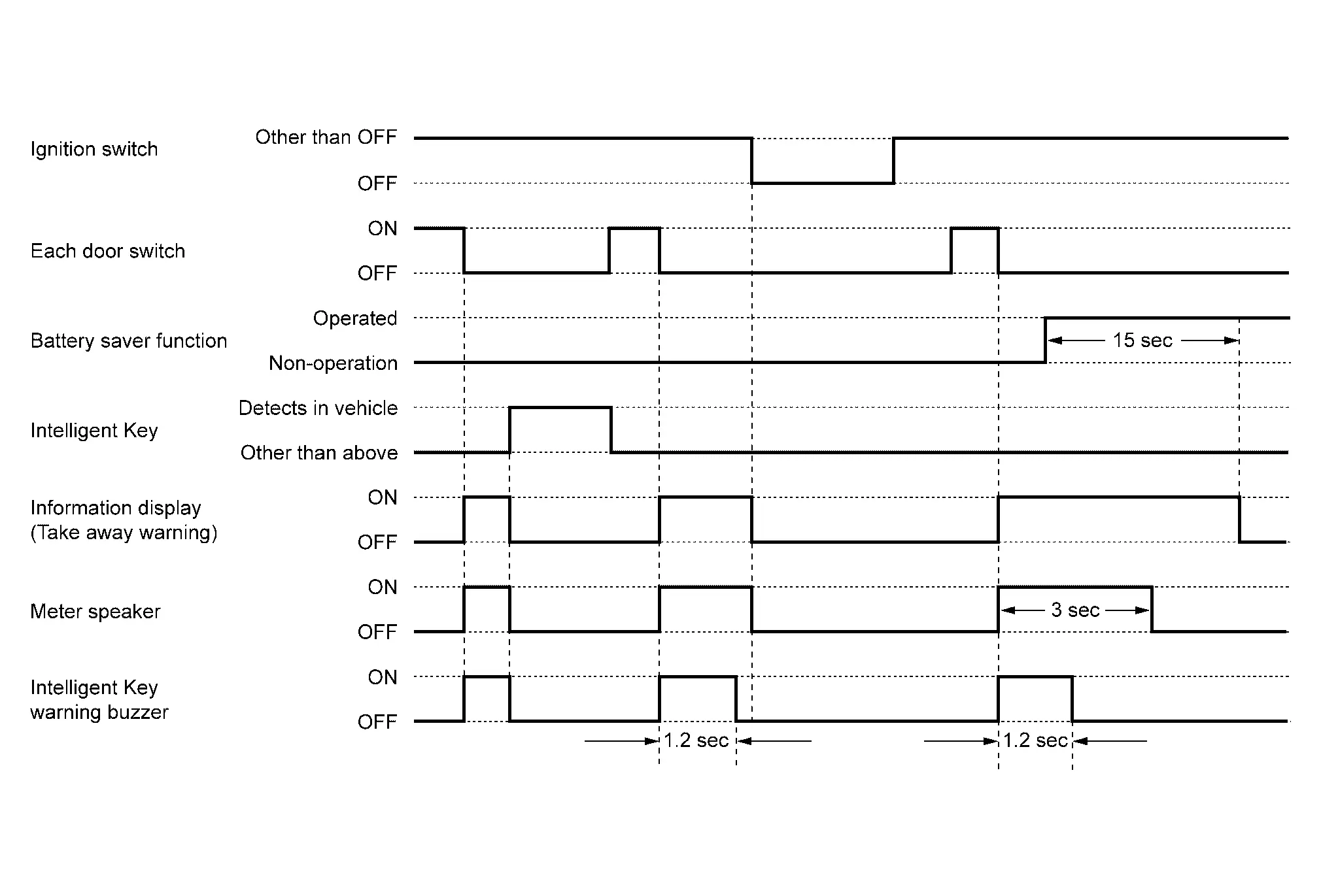
Door status changes from open to close
When all of the following conditions are satisfied
-
Ignition switch is other than OFF
-
Door switch is switched from ON to OFF (Open door is closed)
-
A registered Intelligent Key is not detected in passenger room
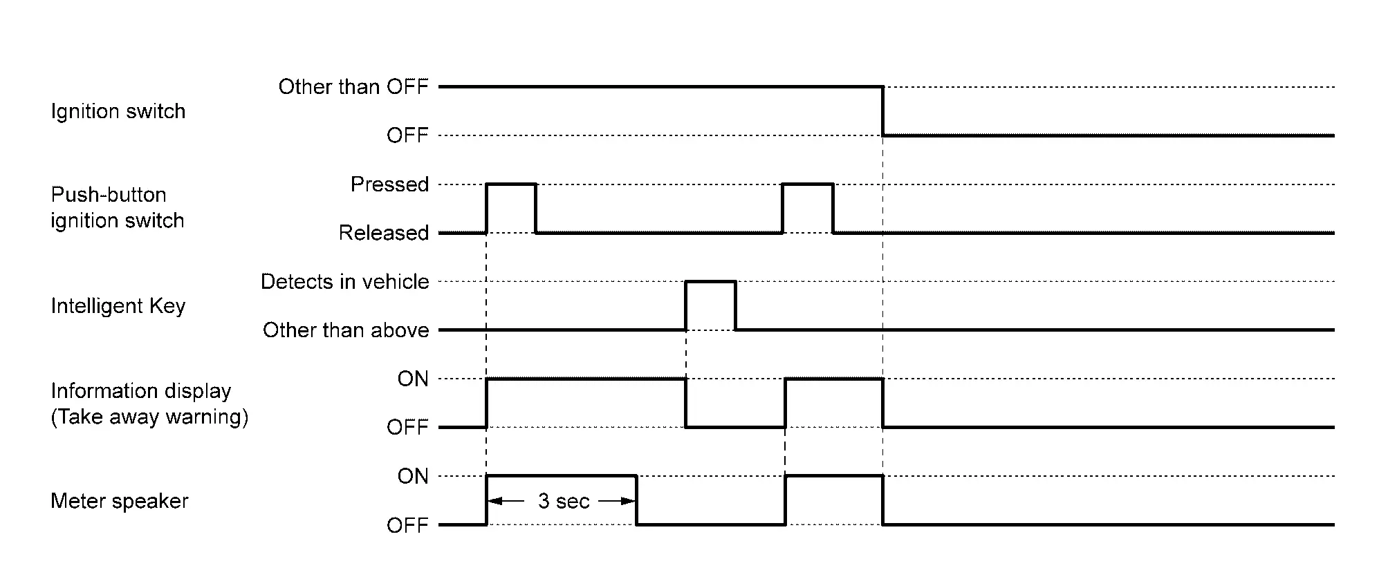
Push-button ignition switch is pressed
When all of the following conditions are satisfied
-
Ignition switch is in OFF
-
A registered Intelligent Key is not detected in passenger room
-
Push-button ignition switch operation is performed
When vehicle speed 9.3 MPH (15 km/h)
When all of the following conditions are satisfied
-
Ignition switch is ON
-
When vehicle speed 9.3 MPH (15 km/h)
-
A registered Intelligent Key is not detected in passenger room
WARNING CANCEL CONDITION
Door status changes from open to close
When any of the following conditions are satisfied
-
Ignition switch is OFF
-
A registered Intelligent Key is detected in passenger room
-
Since warning start, 15 seconds are passed while battery saver system is in operation
Push-button ignition switch is pressed
When any of the following conditions are satisfied
-
Ignition switch is OFF
-
A registered Intelligent Key is detected in passenger room
NOTE:
For battery saver system, refer to System Description.
When vehicle speed 9.3 MPH (15 km/h)
When any of the following conditions are satisfied
-
Ignition switch is OFF
-
A registered Intelligent Key is detected in passenger room
-
Since warning start, 15 seconds are passed
TIMING CHART
Door status changes from open to close
Push-button ignition switch is pressed
When vehicle speed 9.3 MPH (15 km/h)
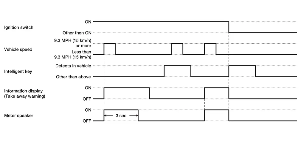
SOUND SPECIFICATION
Meter speaker

Intelligent Key warning buzzer

System Description :: Diagnosis System (combination Meter)
CONSULT Function
Type A
On Board Diagnosis Function
| METER | Refer to On Board Diagnosis Function. |
CONSULT Function (METER)
| METER | Refer to CONSULT Function (METER). |
Type B
On Board Diagnosis Function
| METER | Refer to On Board Diagnosis Function. |
CONSULT Function (METER)
| METER | Refer to CONSULT Function (METER). |
System Description :: Diagnosis System (bcm). Common Item
Common Item
CONSULT Function (BCM - COMMON ITEM)
CONSULT Function (BCM - COMMON ITEM)
Ecu Diagnosis Information :: Combination Meter
List of ECU Reference
| ECU | Reference |
|---|---|
| Combination meter | Reference Value |
| Fail-Safe | |
| DTC Inspection Priority Chart | |
| DTC Index |
| ECU | Reference |
|---|---|
| Combination meter | Reference Value |
| Fail-Safe | |
| DTC Inspection Priority Chart | |
| DTC Index |
Ecu Diagnosis Information :: Bcm
List of ECU Reference
| ECU | Reference |
|---|---|
| BCM | Reference Value (With Type A Meter) with Type A meter |
| Reference Value (With Type B Meter) with Type B meter | |
| Fail-safe | |
| DTC Inspection Priority Chart | |
| DTC Index |
Wiring Diagram :: Warning Chime System - With Type a Meter
Wiring Diagram
Refer to Wiring Diagram.
Wiring Diagram :: Warning Chime System - With Type B Meter
Wiring Diagram
Refer to Wiring Diagram.
Basic Inspection :: Diagnosis and Repair Work Flow
Work Flow
OVERALL SEQUENCE
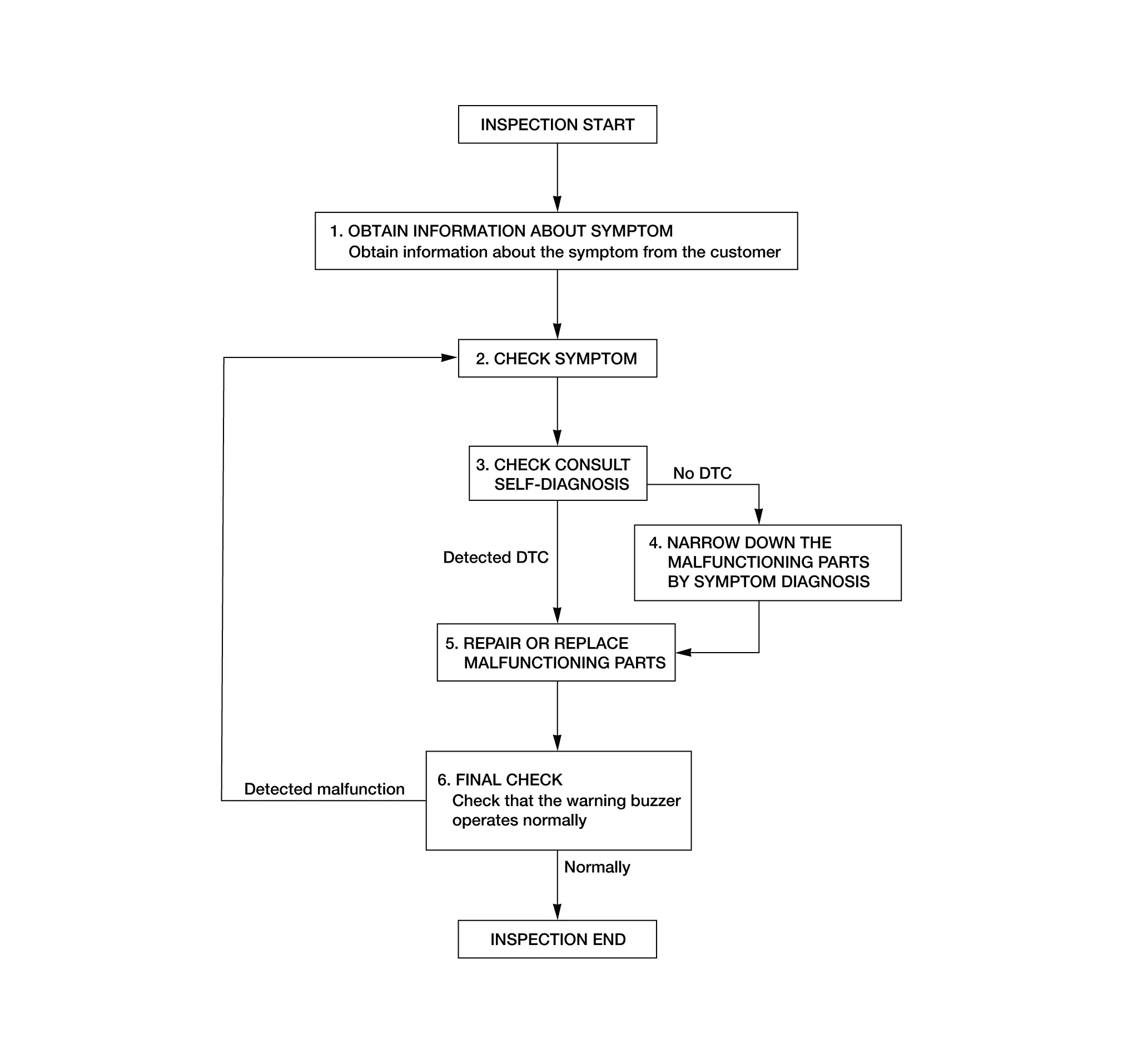
DETAILED FLOW
OBTAIN INFORMATION ABOUT SYMPTOM
Interview the customer to obtain as much information as possible about the conditions and environment under which the malfunction occurred.
>>
GO TO 2.
CHECK SYMPTOM
-
Check the symptom based on the information obtained from the customer.
-
Check if any other malfunctions are present.
>>
GO TO 3.
CHECK CONSULT SELF DIAGNOSIS RESULTS
 CONSULT
-
Select "Self diagnosis result" mode of "METER". Refer to DTC Index (TYPE-A) or DTC Index (TYPE-B).
Is the inspection result normal?
YES>>GO TO 4.
NO>>GO TO 5.
NARROW DOWN MALFUNCTIONING PARTS BY SYMPTOM DIAGNOSIS
Perform symptom diagnosis and narrow down the malfunctioning parts.
>>
GO TO 5.
REPAIR OR REPLACE MALFUNCTIONING PARTS
Repair or replace malfunctioning parts.
NOTE:
If DTC is displayed, erase DTC after repairing or replacing malfunctioning parts.
>>
GO TO 6.
FINAL CHECK
Check that the warning buzzer operates normally.
Is the inspection result normal?
YES>>Inspection End.
NO>>GO TO 1.
Dtc/circuit Diagnosis :: Power Supply and Ground Circuit. Combination Meter
Combination Meter
Diagnosis Procedure
Refer to Diagnosis Procedure (TYPE-A) or Diagnosis Procedure (TYPE-B).
Dtc/circuit Diagnosis :: Meter Speaker Signal Circuit
Diagnosis Procedure
Refer to Diagnosis Procedure (TYPE-A) or Diagnosis Procedure (TYPE-B).
Other materials:
Fuel Rail Pressure Sensor
Component Inspection
CHECK FUEL RAIL PRESSURE (FRP) SENSOR
With CONSULT
Turn ignition switch OFF.
Reconnect harness connector disconnected.
Start engine and warm it up to normal operating temperature.
Select “FUEL PRES SEN V” in “DATA MONITOR” mode of “ENGINE” using ...
Camera Aiming Adjustment
Work Procedure
Always adjust the camera aiming after removing and installing or replacing the front camera unit.
Always adjust the camera aiming after removing and installing or replacing the windshield glass.
CAUTION:
Place the vehicle on level ground when the camera aiming adjust ...
U1caa-02 Mode Door Motor
DTC Description
DTC DETECTION LOGIC DTC No.
CONSULT screen terms
(Trouble diagnosis content) DTC detection condition
U1CAA-02
Mode door motor
(Mode door motor)
Diagnosis condition
Ignition switch ON
Signal (Terminal)
LIN (door motor) signal
Threshold
A/C amp. is no ...