Nissan Rogue (T33) 2021-Present Service Manual: System Description :: Component Parts. Moonroof System
Moonroof System
Component Description
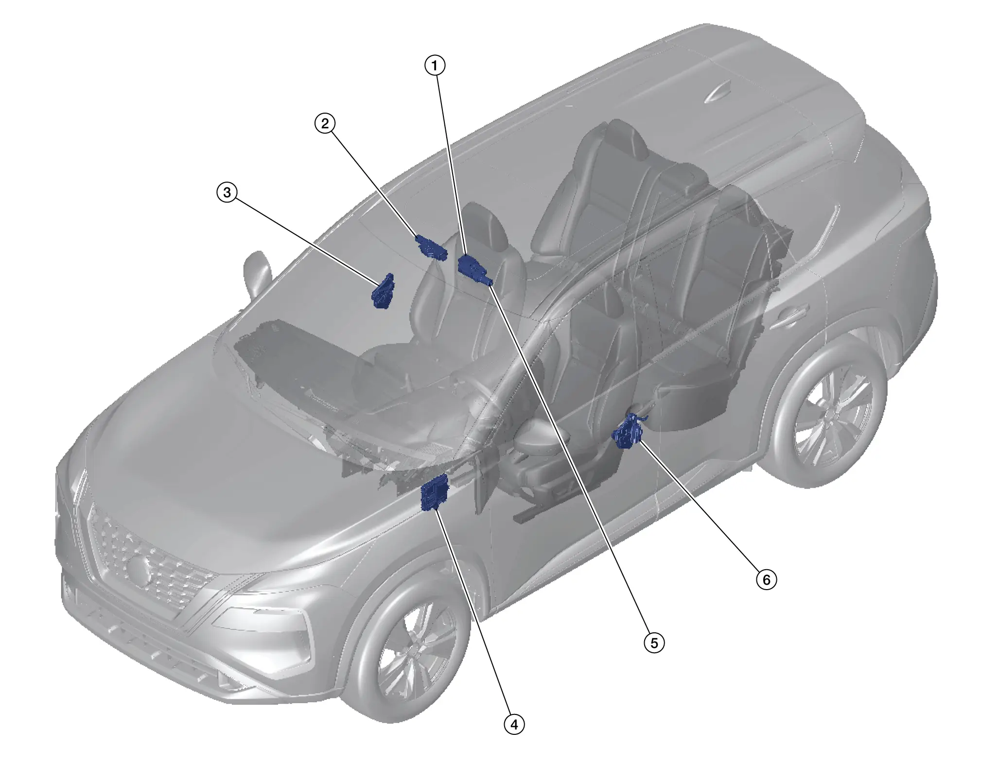
| No. | Component | Function |
|---|---|---|
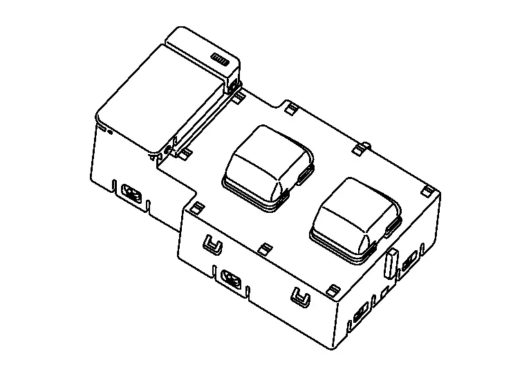
| 1. | Moonroof switch assembly | Refer to Moonroof Switch Assembly. |
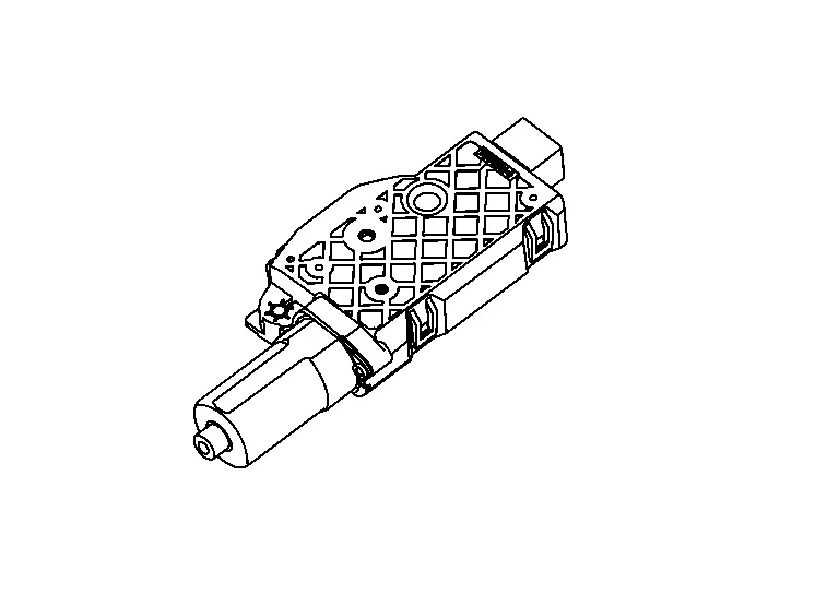
| 2. | Moonroof motor assembly | Refer to Moonroof Motor Assembly. |
| 3. | Front door lock assembly RH (door switch) |
Detects door open/close condition and transmits the signal to the BCM Refer to Component Parts Location for detailed component location. |
| 4. | BCM (Body Control Module) |
Supplies the power supply to the moonroof motor assembly. Refer to Component Parts Location for detailed component location. |
| 5. | Sunshade motor assembly | Refer to Sunshade Motor Assembly. |
| 6. | Front door lock assembly LH (door switch) |
Detects door open/close condition and transmits the signal to the BCM Refer to Component Parts Location for detailed component location. |
Moonroof Switch Assembly
COMPONENT FUNCTION WITHIN SYSTEM
-
Moonroof switch assembly is installed to the map lamp assembly.
-
Transmits operation signal to moonroof motor assembly and sunshade motor assembly.
-
When moonroof switch is operated, it transmits signal to moonroof motor assembly.
-
When sunshade switch is operated, it transmits signal to sunshade motor assembly.
Moonroof Motor Assembly
COMPONENT FUNCTION WITHIN SYSTEM
-
Moonroof motor assembly is installed to moonroof unit assembly.
-
Moonroof motor assembly controls the moonroof.
-
Moonroof motor assembly controls automatic operation.
-
Moonroof motor assembly controls anti-pinch function.
Sunshade Motor Assembly
COMPONENT FUNCTION WITHIN SYSTEM
-
Sunshade motor assembly is installed to moonroof unit assembly.
-
Sunshade motor assembly controls sunshade.
-
Sunshade motor assembly controls automatic operation.
-
Sunshade motor assembly controls anti-pinch function.
Other materials:
Brake Warning Lamp
Component Function Check
CHECK BRAKE WARNING LAMP FUNCTION (1)
Check that brake warning lamp in combination meter turns ON for
approximately 1 second after ignition switch is ON (before engine
start).
Is the inspection result normal?
YES>>
GO TO 2.
NO>>
Refer to Diagnosis Pr ...
Dtc/circuit Diagnosis. B2001-45 Intelligent Key Unit
DTC Description
DTC DETECTION LOGIC DTC No.
CONSULT screen items
(Trouble diagnosis content) DTC Detection Condition
B2001-45
Intelligent Key unit
(Intelligent Key unit)
Diagnosis condition
Ignition switch ON
Signal (terminal)
—
Threshold
Intelligent Key unit is ...
P06db Engine Oil Pressure Control Solenoid Valve
DTC Description
DTC DETECTION LOGIC DTC
CONSULT screen terms
(Trouble diagnosis content)
DTC detection condition
P06DB
00
ENGINE OIL PRESSURE CONTROL
(Engine oil pressure control circuit low)
Diagnosis condition
—
Signal (terminal)
Engine oil pressure control so ...