
Nissan Rogue (T33) 2021-Present Service Manual: System Description :: Component Parts. Electric Parking Brake System
Electric Parking Brake System
Component Parts Location

| A. | Center console |
| No. | Component | Function |
|---|---|---|
| 1. | Parking brake actuator RH | Refer to Parking Brake Actuator. |
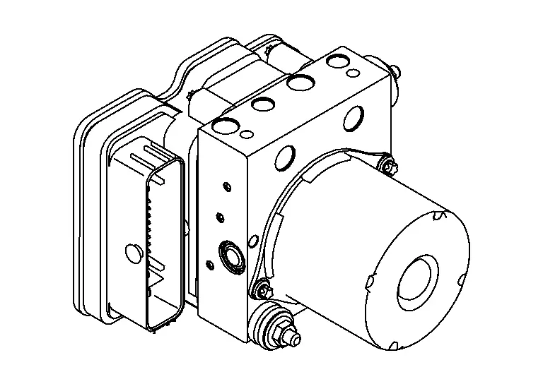
| 2. | ABS (Anti-lock Braking System) actuator and electric unit (control unit) | Refer to ABS Actuator and Electric Unit (Control Unit). |
| 3. | Parking brake actuator LH | Refer to Parking Brake Actuator. |
| 4. | Parking brake switch indicator | Refer to Parking Brake Switch. |
| 5. | Parking brake switch |
ABS Actuator and Electric Unit (Control Unit)
FUNCTIONS WITHIN THE SYSTEM
-
The parking brake actuator is controlled by the signals from the parking brake switch, sensors, and units.
 NOTE:
The parking brake is released and applied by controlling the parking brake actuator.
-
When a malfunction is detected, the system enters fail-safe mode.
INDIVIDUAL FUNCTIONS WITHIN THE SYSTEM
Controls the parking brake actuator.
PARTS LOCATION
Refer to Component Parts Location.
Parking Brake Switch
FUNCTIONS WITHIN THE SYSTEM
Parking brake is applied/released by the parking brake switch operation.

INDIVIDUAL FUNCTIONS WITHIN THE SYSTEM
-
When the parking brake switch is pushed / pulled, the circuit between the ABS actuator and electric unit (control unit) is established to input the switch signal.
-
When parking brake is applied, parking brake switch indicator lamp is turned ON by the ABS actuator and electric unit (control unit).
INDIVIDUAL OPERATION
Parking brake switch is constructed by a combination of normal open type switch and normal close type switch. And the switch circuit is connected in parallel.

-
Parking brake switch is pull: Parking brake is apply and parking brake switch indicator lamp is turn ON.
-
Parking brake switch is push: Parking brake is release and parking brake switch indicator lamp is turn OFF.
PARTS LOCATION
Refer to Component Parts Location.
Parking Brake Actuator
FUNCTIONS WITHIN THE SYSTEM
The parking brake actuator  activates / releases the parking brake by moving the piston of the rear brake caliper
 according to the signal from the ABS actuator and electric unit (control unit).

INDIVIDUAL FUNCTIONS WITHIN THE SYSTEM
Parking brake actuator is composed of a motor, gear, etc.
INDIVIDUAL OPERATION
It operates/releases the parking brake by transmitting the motor rotation output to the piston of the rear brake caliper.
NOTE:
Braking condition is mechanically maintained. It is not always controlled.
PARTS LOCATION
Refer to Component Parts Location.
CAUTION:
Never reuse the parking brake actuator if the parking brake actuator is removed from the rear brake caliper.
Other materials:
Dtc/circuit Diagnosis. Brake Warning Lamp
Component Function Check
CHECK BRAKE WARNING LAMP FUNCTION (1)
Check that brake warning lamp turns ON for several second after Ignition switch is turned ON.
Is the inspection result normal?
YES>>
GO TO 2.
NO>>
Refer to Diagnosis Procedure.
CHECK BRAKE WARNING LAMP FUNCTION (2)
...
Dtc/circuit Diagnosis. U2250-87 Can Comm Err (air Bag)
DTC Description
DESCRIPTIONCAN (Controller Area Network) is a serial
communication line for real time applications. It is an on-Nissan Ariya
vehicle multiplex communication line with high data communication speed
and excellent error detection ability. Modern Nissan Ariya vehicle is
equipped ...
Steering Switch Signal B Circuit
Component Function Check
CHECK COMBINATION METER INPUT SIGNAL
CONSULT
Ignition switch ON.
Select “Steering switch input� in “Data monitor� mode of “M&A�.
Check that the function operates normally according to the following conditions:
Condition Value
CONTRO ...