Nissan Rogue (T33) 2021-Present Service Manual: Steering Switch Signal B Circuit
Component Function Check
CHECK COMBINATION METER INPUT SIGNAL
 CONSULT
-
Ignition switch ON.
-
Select “Steering switch input” in “Data monitor” mode of “M&A”.
-
Check that the function operates normally according to the following conditions:
| Condition | Value |
|---|---|
| CONTROL switch is pressed | SW1 |
| Jog dial is rotated to upward | SW2 |
| Jog dial is rotated to downward | SW3 |
| OK switch is pressed | SW4 |
| LEFT/BACK switch is pressed | SW5 |
| RIGHT switch is pressed | SW6 |
| VOL DOWN switch is pressed | SW7 |
| VOL UP switch is pressed | SW8 |
| TEL END switch is pressed | SW9 |
| VR/TEL switch is pressed | SW10 |
| SEEK DOWN switch is pressed | SW11 |
| SEEK UP switch is pressed | SW12 |
| Other than above | NO INPUT |
Is the inspection result normal?
YES>>Inspection End.
NO>>Refer to Diagnosis Procedure.
Diagnosis Procedure
CHECK STEERING SWITCH SIGNAL B CIRCUIT
-
Disconnect combination meter harness connector and spiral cable harness connector.
-
Check continuity between combination meter harness connector and spiral cable harness connector.
Combination meter Spiral cable Continuity Connector Terminal Connector Terminal M76 23 M30 9 Yes -
Check continuity between combination meter harness connector and ground.
Combination meter Ground Continuity Connector Terminal M76 23 No
Is the inspection result normal?
YES>>GO TO 2.
NO>>Repair harness or connector.
CHECK STEERING SWITCH SIGNAL GROUND CIRCUIT
-
Check continuity between combination meter harness connector and spiral cable harness connector.
Combination meter Spiral cable Continuity Connector Terminal Connector Terminal M76 34 M30 11 Yes -
Check continuity between combination meter harness connector and ground.
Combination meter Ground Continuity Connector Terminal M76 34 No
Is the inspection result normal?
YES>>GO TO 3.
NO>>Repair harness or connector.
CHECK SPIRAL CABLE
-
Disconnect spiral cable harness connectors.
-
Check continuity between spiral cable harness connectors.
Spiral cable Continuity Connector Terminal Connector Terminal M154 23 M30 9 Yes 25 11
Is the inspection result normal?
YES>>GO TO 4.
NO>>Replace spiral cable. Refer to Removal and Installation.
CHECK STEERING SWITCH
Check steering switch. Refer to Component Inspection.
Is the inspection result normal?
YES>>Inspection End.
NO>>Replace steering switches. Refer to Removal and Installation.
Component Inspection
CHECK STEERING SWITCH
-
Remove steering switch. Refer to Removal and Installation.
-
Measure the resistance between the steering switch connector.
Steering switch Condition Resistance
(Approx.) ΩTerminal 23 25 SEEK UP switch is pressed 2080.54 – 2165.46 SEEK DOWN switch is pressed 639.94 – 666.06 TEL/VR switch is pressed 257.74 – 268.26 TEL END switch is pressed 130.34 – 135.66 VOL UP switch is pressed 49.98 – 52.02 VOL DOWN switch is pressed 1 or less 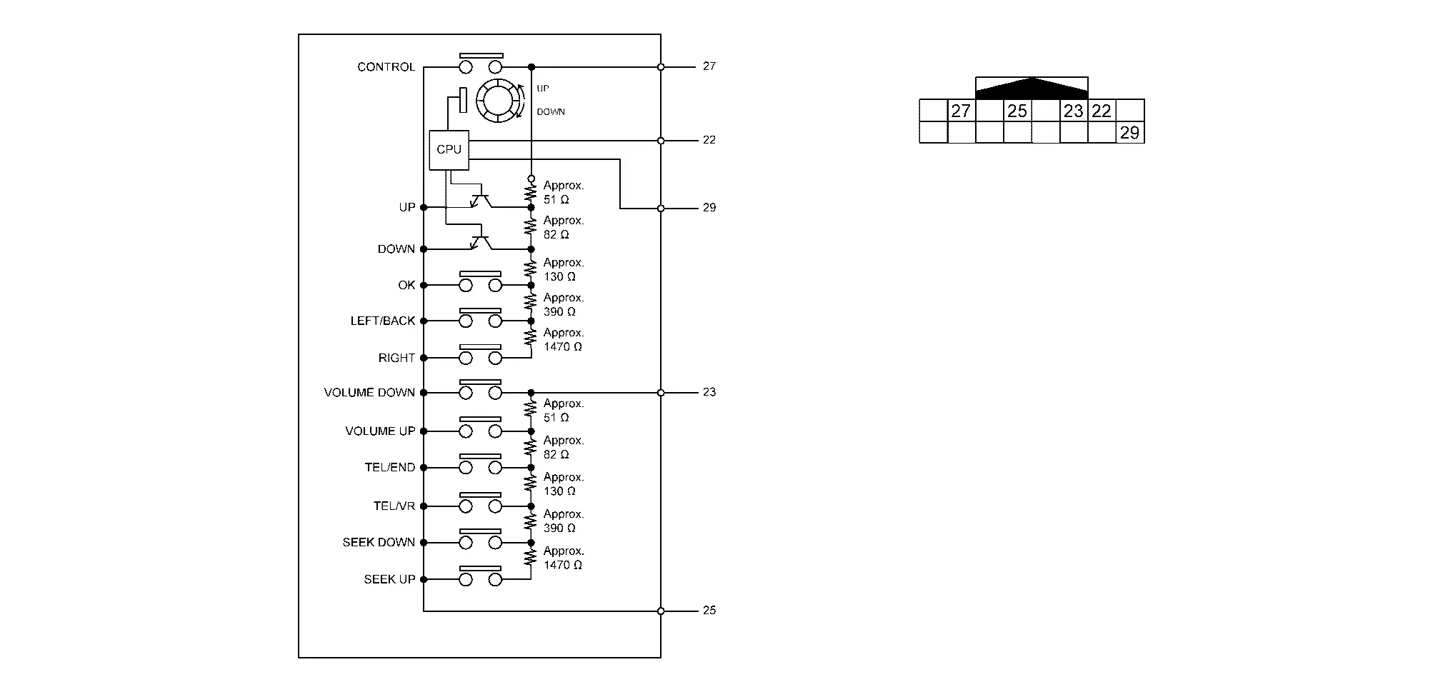
Is the inspection result normal?
YES>>Inspection End.
NO>>Replace steering switch. Refer to Removal and Installation.
Other materials:
Three Way Catalyst
Exploded View
Air fuel ratio (A/F) sensor 1
Manifold washer
Stud bolt
Catalyst support bracket
Three way catalyst
Heated oxygen sensor 2
Turbo gasket (OUT)
V-band clamp
Comply with the assembly procedure when tightening. Refer to Remo ...
P0500 Vss
DTC Description
DESCRIPTIONECM receives vehicle speed signals from two
different paths via CAN communication line: One is from the ABS actuator
and electric unit (control unit) via the combination unit and the other
is from TCM.DTC DETECTION LOGIC DTC
CONSULT screen terms
(Trouble diagno ...
Fonctionnement du système LDW
Témoin LDW (affiché sur l’écran d’informations du véhicule)
Écran d’informations du véhicule
Commandes au volant (côté gauche)
Le système LDW du Nissan Rogue active la fonction d’alerte sortie de voie lorsque la vitesse du véhicule atteint environ 60 km/h (37 mi ...