Nissan Rogue (T33) 2021-Present Service Manual: System Description :: Component Parts. Door Lock System
Door Lock System
Power Door Lock System
Component Parts Location
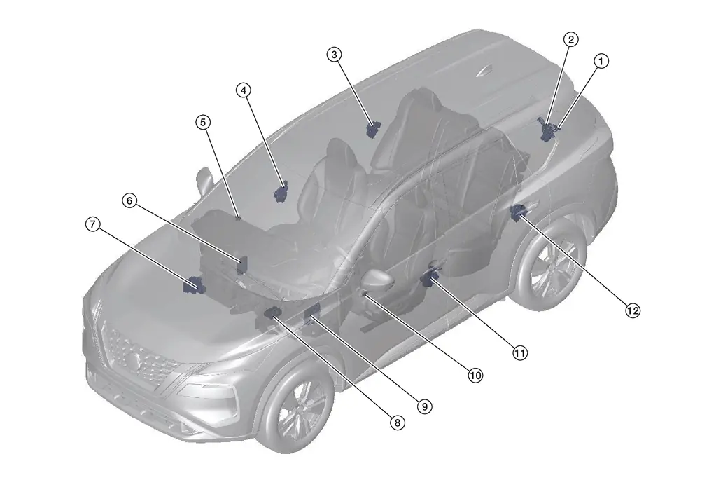
| No. | Component | Function |
|---|---|---|
| 1. | Back door opener switch | Back door opener switch sends signal to BCM to open the back door. |
| 2. | Back door lock assembly | Refer to Back Door Lock Assembly. |
| 3. | Rear door lock assembly RH | Rear door lock assembly locks/unlocks the rear door latch assembly. |
| 4. | Front door lock assembly RH | Front door lock assembly locks/unlocks the front door latch assembly. |
| 5. | Door lock/unlock switch RH | Refer to Door Lock/Unlock Switch. |
| 6. | TCU (Telematics Communication Unit) |
Transmit door lock/unlock signal to BCM via CAN communication. Refer to Component Parts Location for detailed component location. |
| 7. | ABS (Anti-lock Braking System) actuator and electric unit (control unit) |
Tranmits Nissan Ariya vehicle speed signal to BCM ua CAN communication. Refer to Component Parts Location for detailed component location. |
| 8. | Electric shift control module |
Tranmists shift position signal to BCM via CAN communication. Refer to Component Parts Location for detailed component location. |
| 9. | BCM (Body Control Module) |
|
| 10. | Door lock/unlock switch LH |
Main power window and door lock/unlock switch sends signal to BCM to lock or unlock doors. Refer to Door Lock/Unlock Switch. |
| 11. | Front door lock assembly LH |
Front door lock assembly locks/unlocks the front door latch assembly. Refer to Door Lock Assembly. |
| 12. | Rear door lock assembly LH |
Rear door lock assembly locks/unlocks the rear door latch assembly. Refer to Door Lock Assembly. |
Intelligent Key System
Component Parts Location
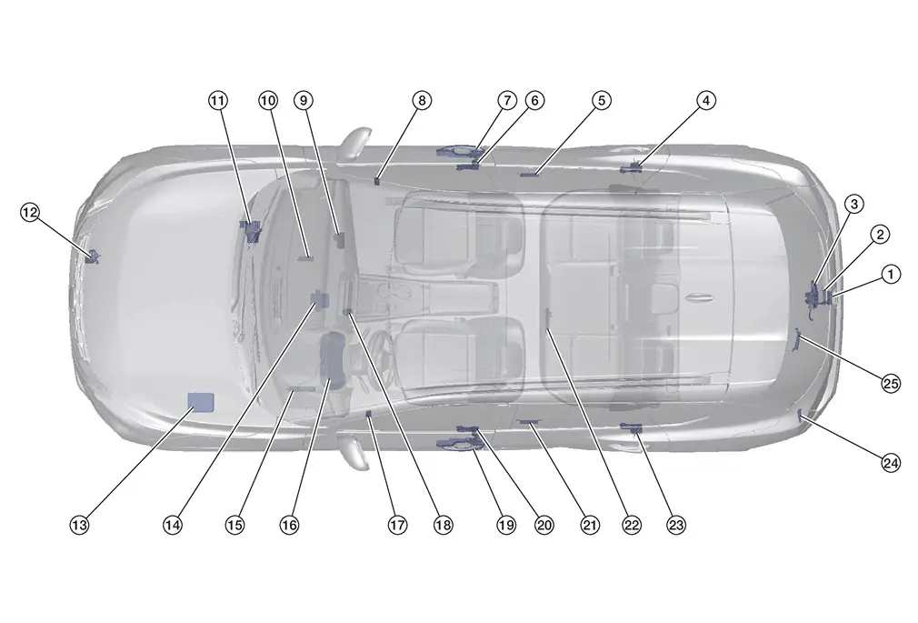
| No. | Component | Function |
|---|---|---|
| 1. | Back door opener switch |
Back door request switch is integrated into the back door opener switch. Back door request switch transmits door lock/unlock request signal to the BCM. Refer to Back Door Opener Switch. |
| 2. | Outside key antenna (rear bumper) |
Outside key antenna (rear bumper) detects whether Intelligent Key is outside the Nissan Ariya vehicle or not, and then transmits the singal to the Intelligent Key unit. Refer to Outside Key Antenna. |
| 3. | Back door lock assembly (ajar switch) |
Back door lock assembly locks/unlocks the back door latch. Refer to Back Door Lock Assembly. |
| 4. | Rear door lock assembly RH |
Rear door lock assembly locks/unlocks the rear door latch. Refer to Door Lock Assembly. |
| 5. | Outside key antenna (rear door RH) |
Outside key antenna (RH) detects whether Intelligent Key is outside the Nissan Ariya vehicle or not, and then transmits the signal to the Intelligent Key unit. Refer to Outside Key Antenna. |
| 6. | Front door lock assembly RH |
Front door lock assembly locks/unlocks the front door latch. Refer to Door Lock Assembly. |
| 7. | Front door request switch RH |
Door request switch transmits door lock/unlock request signal to the Intelligent Key unit. Refer to Door Request Switch. |
| 8. | Door lock/unlock switch RH | Refer to Door Lock/Unlock Switch. |
| 9. | Intelligent Key unit | Refer to Intelligent Key Unit. |
| 10. | TCU (Telematics Communication Unit) |
Transmits the lock/unlock request signal to BCM via CAN communcation. Refer to Component Parts Location for detailed component location. |
| 11. | ABS (Anti-lock Braking System) actuator and electric unit (control unit) |
Transmits the Nissan Ariya vehicle speed signal to the Intelligent Key unit via CAN communication. Refer to Component Parts Location for detailed component location. |
| 12. | Horn | Horn is operated when the panic button on the Intelligent Key is pressed or the alarm is activated. |
| 13. | IPDM E/R (Intelligent Power Distribution Module Engine Room) |
IPDM E/R activates horns. Refer to Component Parts Location for detailed component location. |
| 14. | Electric shift control module |
Transmits shift selector lever position to BCM via CAN communication. Refer to Component Parts Location for detailed component location. |
| 15. | BCM (Body Control Module) |
BCM controls NISSAN Nissan Ariya Vehicle IMMOBILIZER SYSTEM-NATS [NVIS (NATS)] and VEHICLE SECURITY SYSTEM. BCM performs the ID verification between BCM and Intelligent Key when the Intelligent Key is carried into the detection area of inside key antenna, and ignitino switch is placed in the ON position. If the ID verfication result is OK, ignition switch operation is available. Then, when the ignition switch is placed in the ON position, BCM performs ID verification between BCM and ECM. If the ID verfication result is OK, ECM can start engine. Refer to Component Parts Location for detailed component location. |
| 16. | Combination meter |
Performs opoeration method guide and warning with buzzer. Refer to Component Parts Location (with type A meter), or Component Parts Location (with type B meter), for detailed component location. |
| 17. | Door lock/unlock switch LH | Refer to Door Lock/Unlock Switch. |
| 18. | Push-button ignition switch (NATS antenna amp.) | Push-button ignition switch has push switch inside when it detects that push-button ignition switch is pressed, and then transmits ON/OFF signal to Intelligent Key unit. BCM changes the ignition switch position with the operation of push-button ignition switch. BCM maintains the igntiion switch position status while push-button ignition switch is not operated. |
| 19. | Front door request switch LH |
Door request switch transmits door lock/unlock request signal to the Intelligent Key unit. Refer to Door Request Switch. |
| 20. | Front door lock assembly LH |
Rear door lock assembly locks/unlocks the rear door latch. Refer to Door Lock Assembly. |
| 21. | Outside key antenna (rear door LH) |
Outside key antenna (LH) detects whether Intelligent Key is outside the Nissan Ariya vehicle or not, and then transmits the signal to the Intelligent Key unit. Refer to Outside Key Antenna. |
| 22. | Inside key antenna (USA production) |
Inside key antenna detects whether Intelligent Key is inside the Nissan Ariya vehicle or not, and then transmits the signal to the Intelligent Key unit. Refer to Inside Key Antenna. |
| 23. | Rear door lock assembly LH |
Rear door lock assembly locks/unlocks the rear door latch. Refer to Door Lock Assembly. |
| 24. | Intelligent Key warning buzzer |
Intelligent Key warning buzzer warns the user, who is outside the Nissan Ariya vehicle, of operation confirmation according to Intelligent Key operation and door request switch operation, or of an inappropriate operation. Refer to Intelligent Key Warning Buzzer. |
| 25. | Inside key antenna (Japan production) |
Inside key antenna detects whether Intelligent Key is inside the Nissan Ariya vehicle or not, and then transmits the signal to the Intelligent Key unit. Refer to Inside Key Antenna. |
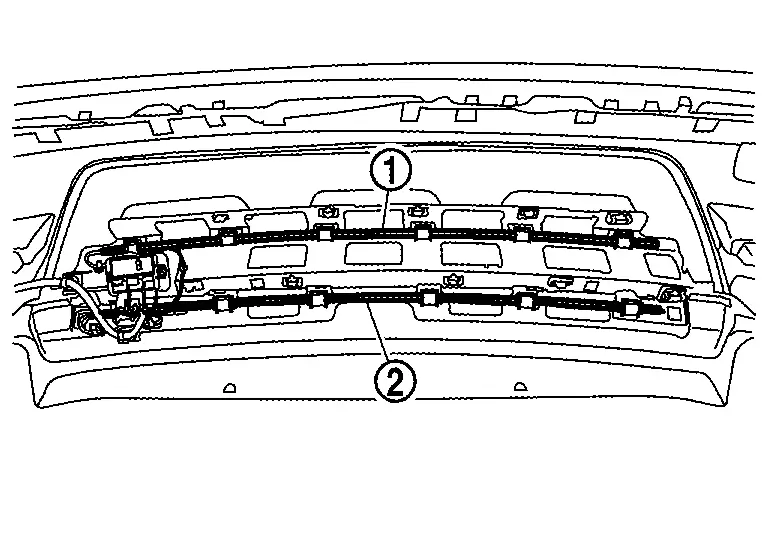
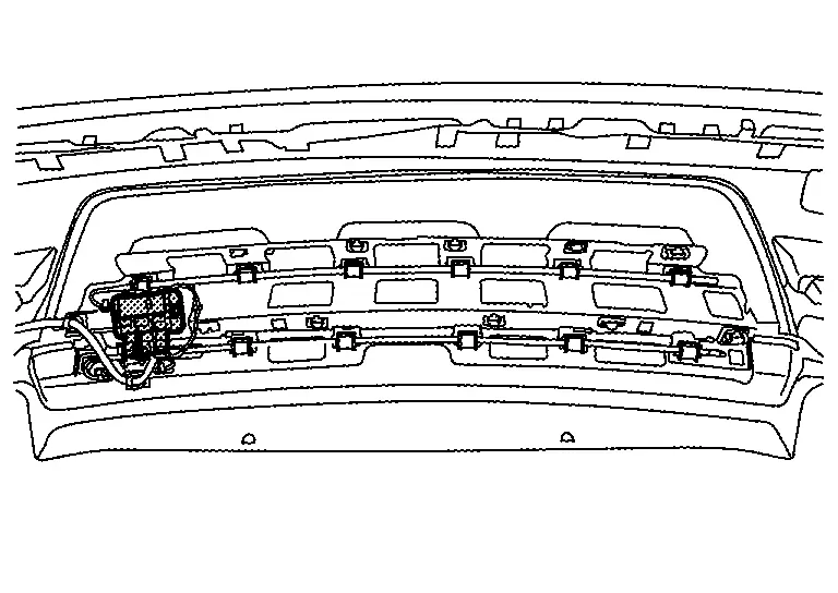
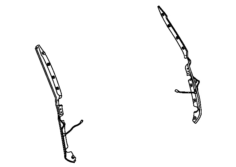
Automatic Back Door System
Component Parts Location
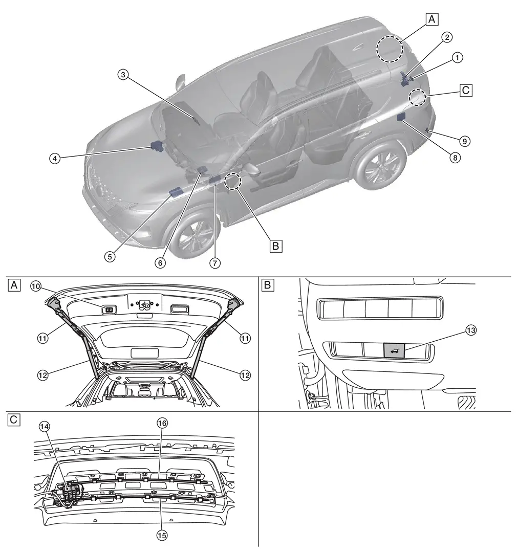
| A. | View of back door open | B. | View of LH side of instrument panel | C. | View of rear fascia removed |
| No. | Component | Function |
|---|---|---|
| 1. | Back door opener switch | Refer to Back Door Opener Switch. |
| 2. | Back door lock assembly | Refer to Back Door Lock Assembly. |
| 3. | Intelligent Key unit | Refer to Intelligent Key Unit. |
| 4. | ABS (Anti-lock Braking System) actuator and electric unit (control unit) |
ABS actuator and electric unit (control unit) communicates Nissan Ariya vehicle speed signal to automatic back door control unit via CAN communication. Refer to Component Parts Location for detailed component location. |
| 5. | IPDM E/R (Intelligent Power Distribution Module Engine Room) |
Communicates ignition status via CAN communication to automatic back door control unit Refer to Component Parts Location for detailed component location. |
| 6. | Electric shift control module |
Electric shift control module communicates shift position signal to automatic back door control unit via CAN communication. Refer to Component Parts Location for detailed component location. |
| 7. | BCM (Body Control Module) |
Transmits and receives signal to the automatic back door control unit. Refer to Component Parts Location for detailed component location. |
| 8. | Automatic back door control unit | Refer to Automatic Back Door Control Unit. |
| 9. | Intelligent Key warning buzzer | Refer to Intelligent Key Warning Buzzer. |
| 10. | Automatic back door lock and close switch assembly | Refer to Automatic Back Door Lock and Close Switch Assembly. |
| 11. | Touch sensor | Refer to Touch Sensor. |
| 12. | Spindle unit | Refer to Spindle Unit. |
| 13. | Automatic back door switch | Refer to Automatic Back Door Switch. |
| 14. | Hands free sensor control unit | Refer to Hands Free Sensor Control Unit. |
| 15. | Hands free sensor (lower side) | Refer to Hands Free Sensor. |
| 16. | Hands free sensor (upper side) | Refer to Hands Free Sensor. |
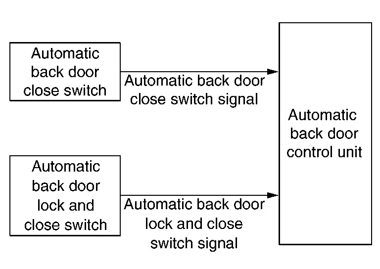
Automatic Back Door Lock and Close Switch Assembly
COMPONENT FUNCTION WITHIN SYSTEM
-
When automatic back door close switch
 is pressed, back door auto close or reverse operation.
 -
When automatic back door lock and close switch
 is pressed, back door auto close and door lock operation.
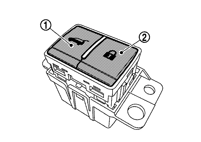
INDIVIDUAL COMPONENT FUNCTION
-
The automatic back door close switch transmits the automatic back door close switch signal to the automatic back door control unit.
-
The automatic back door lock and close switch transmits the automatic back door lock and close switch signal to the automatic back door control unit.
COMPONENT OPERATION
| Condition | |
|---|---|
| Released | Pressed |
|
|
|
COMPONENT PARTS LOCATION
Automatic back door lock and close switch assembly is installed back door inner finisher. Refer to Component Parts Location.
Automatic Back Door Control Unit
COMPONENT FUNCTION WITHIN SYSTEM
The automatic back door control unit detects the statuses of the back door and the vehicle using various signals to control the automatic back door system.
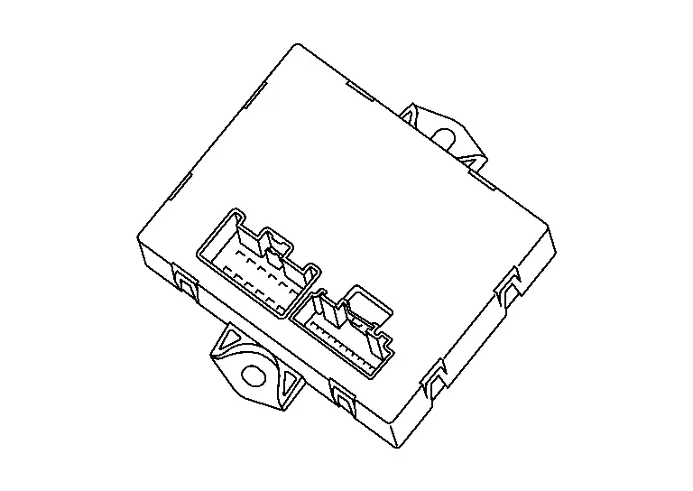
INDIVIDUAL COMPONENT FUNCTION
Automatic back door control unit controls the automatic back door system.
COMPONENT PARTS LOCATION
Automatic back door control unit is installed behind luggage side lower finisher LH. Refer to Component Parts Location.
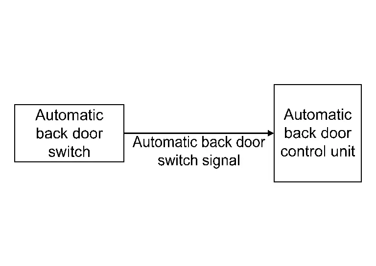
Automatic Back Door Switch
COMPONENT FUNCTION WITHIN SYSTEM
When automatic back door switch is pressed, back door auto open/close operation.
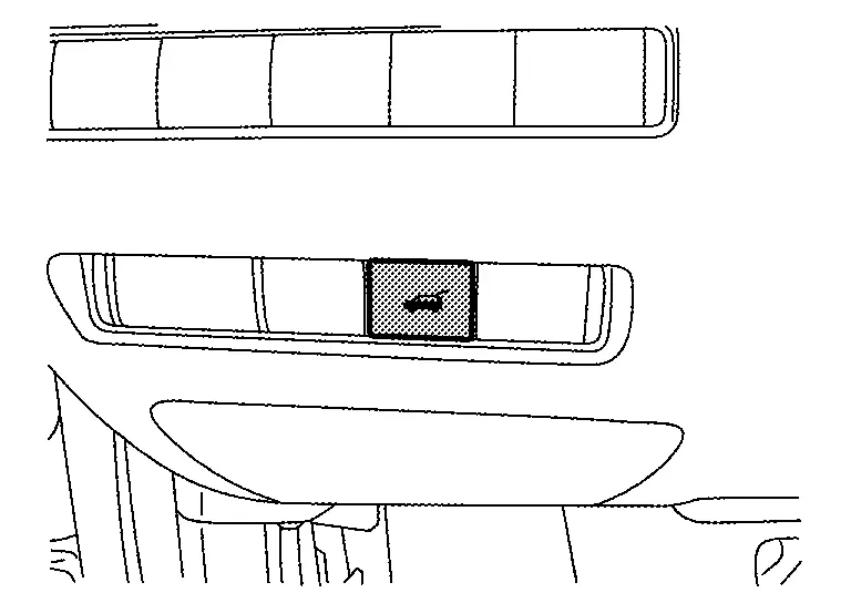
INDIVIDUAL COMPONENT FUNCTION
Transmits automatic back door switch signal to automatic back door control unit.
COMPONENT OPERATION
| Condition | |
|---|---|
| Released | Pressed |
|
|
|
COMPONENT PARTS LOCATION
Automatic back door switch is installed instrument lower panel LH. Refer to Component Parts Location.
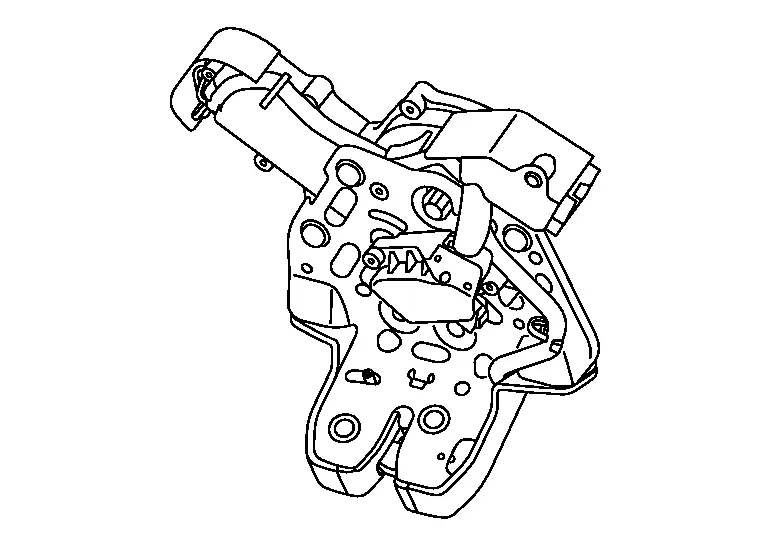
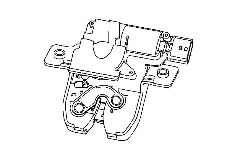
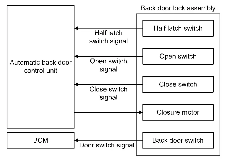
Back Door Lock Assembly
COMPONENT FUNCTION WITHIN SYSTEM
-
With automatic back door
The back door lock assembly detects the back door status of the automatic back door system.
-
Without automatic back door
-
The back door opener actuator opens the back door according to the operation signal from the BCM.
-
The back door switch detects the open/close status of the back door and transmits the door switch signal to the BCM.
-
INDIVIDUAL COMPONENT FUNCTION
-
With automatic back door
-
Back door lock assembly integrates closure motor, half latch switch, open switch, close switch and back door switch.
-
Closure motor: Inputs open/close signal from automatic back door control unit and activates the back door auto closure operation.
-
Half latch switch: Detects half status of back door.
-
Open switch: Stops the closure motor open operation.
-
Close switch: Stops the closure motor close operation
-
Back door switch: Detects open/close status of back door.
-
-
Without automatic back door
Back door lock assembly has back door opener actuator and back door switch built-in.
COMPONENT OPERATION
| Description | Condition | |
|---|---|---|
| Back door switch | Back door close |
|
| Back door open |
|
|
| Half latch switch* | Back door fully closed/half latch |
|
| Back door open |
|
|
| Open switch* | Back door closure operation (close) |
|
| Other than above |
|
|
| Close switch* | Back door closure operation (open) |
|
| Other than above |
|
|
*: With automatic back door
COMPONENT PARTS LOCATION
Back door lock assembly is installed in back door panel. Refer to Component Parts Location.
Back Door Opener Switch
COMPONENT FUNCTION WITHIN SYSTEM
-
When the BCM receives the back door opener switch signal, it opens the back door.
-
When the Intelligent Key unit receives the door request switch signal, it unlocks all the doors.
INDIVIDUAL COMPONENT FUNCTION
-
The back door opener switch
detects back door opening operations and transmits the back door opener switch signal to the BCM. -
The door request switch
detects
door lock/unlock operations from the outside of the Nissan Ariya
vehicle and transmits the door request switch signal to the Intelligent
Key unit.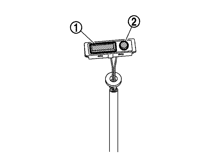
COMPONENT OPERATION
-
Back door opener switch
Condition Pressed Released
Close
Open
-
Door request switch
Condition Pressed Released
Close
Open
COMPONENT PARTS LOCATION
-
Back door opener switch assembly has back door opener switch and back door request switch built-in.
-
Back door opener switch assembly is installed in back door panel. Refer to Component Parts Location.
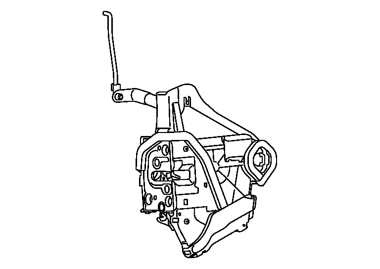
Door Lock Assembly
COMPONENT FUNCTION WITHIN SYSTEM
-
Door lock actuator locks/unlocks door.
-
Detects door open/close condition.
-
Unlock sensor detects lock/unlock status of driver side front door.
INDIVIDUAL COMPONENT FUNCTION
-
Door lock actuator receives lock/unlock signal from BCM, and then locks/unlocks door.
-
Unlock sensor transmits lock/unlock status of driver side front door to BCM.
-
Transmits door switch signal to BCM.
COMPONENT OPERATION
| Condition | |
|---|---|
| Door lock | Door unlock |
|
|
|
| Condition | |
|---|---|
| Door close | Door open |
|
|
|
COMPONENT PARTS LOCATION
-
Door lock actuator and door switch is integrated in the door lock assembly.
-
Unlock sensor is integrated in front door lock assembly (driver side).
-
Door lock assemblies are installed in each doors. Refer to Component Parts Location.
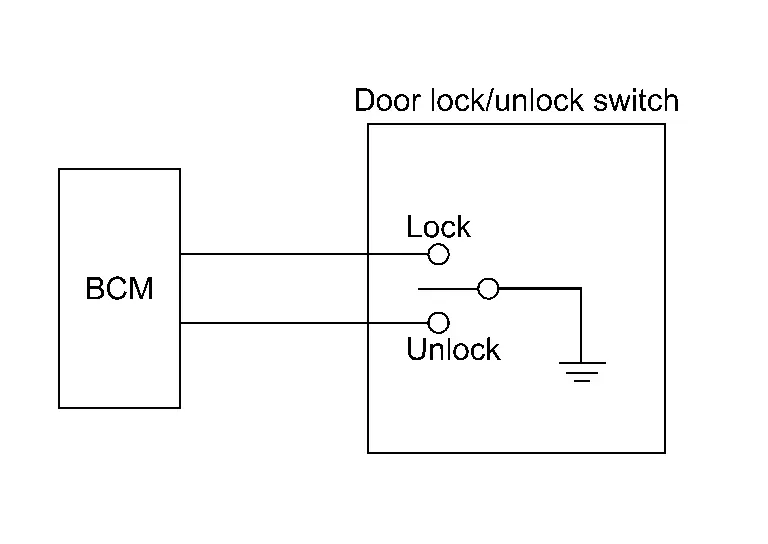
Door Lock/Unlock Switch
COMPONENT FUNCTION WITHIN SYSTEM
Detects door lock/unlock operation.
INDIVIDUAL COMPONENT FUNCTION
Transmits door lock/unlock switch signal to BCM.
COMPONENT OPERATION
| Condition | |
|---|---|
| Door lock/unlock operation | Door lock/unlock not operation |
|
|
|
COMPONENT PARTS LOCATION
-
Door lock/unlock switch is integrated in front door finisher.
-
For details: Refer to Component Parts Location.
Door Request Switch
COMPONENT FUNCTION WITHIN SYSTEM
Detects door lock/unlock operation.
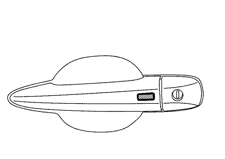
INDIVIDUAL COMPONENT FUNCTION
Transmits door request switch signal to Intelligent Key unit.
COMPONENT OPERATION
| Condition | |
|---|---|
| Released | Pressed |
|
|
|
COMPONENT PARTS LOCATION
Door request switches are installed in the outside handle. Refer to Component Parts Location.
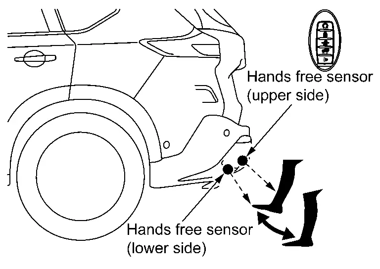
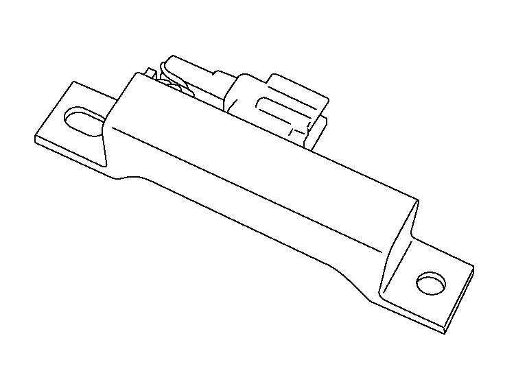
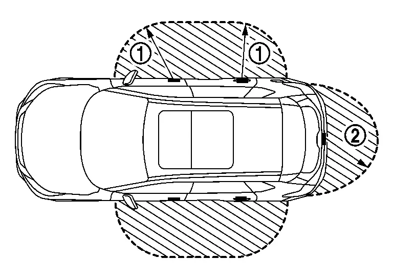
Hands Free Sensor
COMPONENT FUNCTION WITHIN SYSTEM
-
When the user performs a kick motion toward rear bumper while carrying Intelligent Key as shown in the figure, hands free sensor (upper side) detects shin motion of leg and hands free sensor (lower side) detects instep motion of foot. This varies the voltage waveform of hands free sensor. Hands free sensor control unit judges user operation by detecting the voltage change of hands free sensor.
 NOTE:
NOTE:
Quick forward kick and return while the Intelligent Key is within range. Wait approximately 2 seconds after kick.
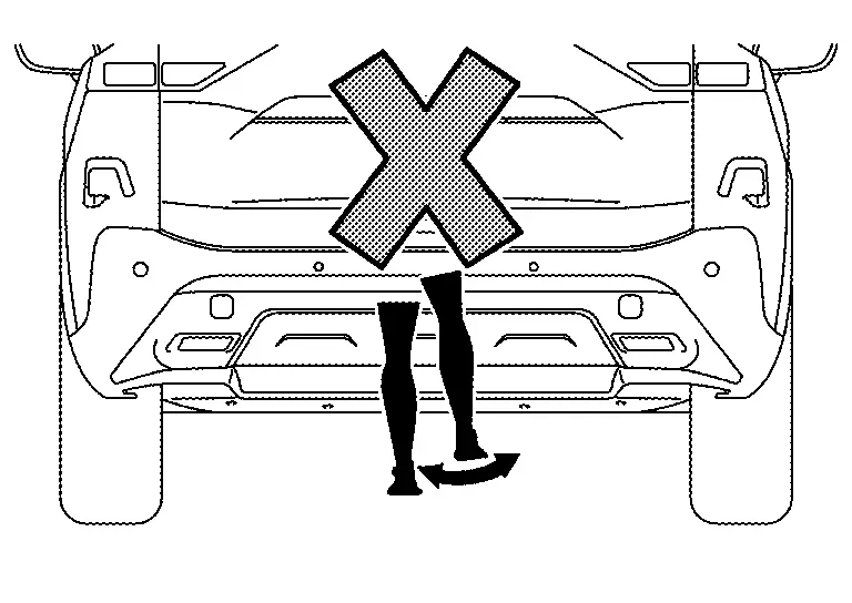 NOTE:
NOTE:
Do not swing foot side to side or pause during kick.
NOTE:
Voltage generated in communication circuit between hands free sensor and hands free sensor control unit is extremely low and therefore cannot be measured.
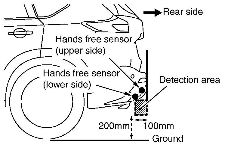
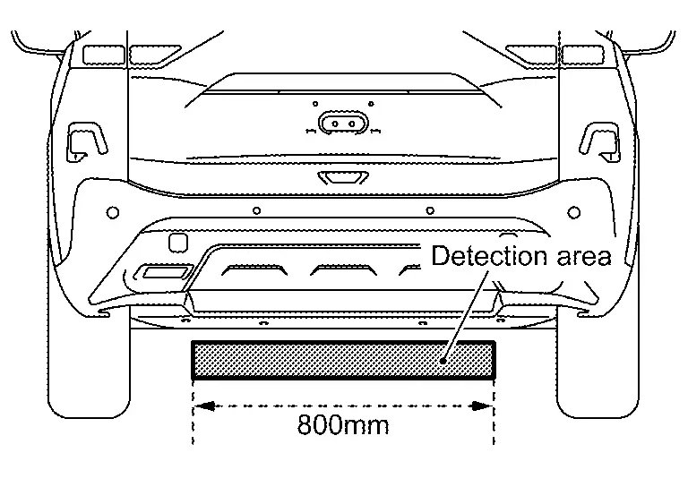
-
It is necessary to perform hands free within space as shown in the figure for activating the hands free sensor completely. The detection area may differ depending on the conditions of the surroundings.
-
Intelligent Key must be carried for starting the operation of the automatic back door open/close function by hands free sensor operation (hands free function) with the back door stopped. Intelligent Key does not need to be carried when stopping the back door operation during automatic back door open/close operation (automatic open/close temporary stop function).
INDIVIDUAL COMPONENT FUNCTION
The hands free sensor converts the approaching of feet to voltage and transmits it to the hands free sensor control unit.
COMPONENT PARTS LOCATION
Hands free sensor (upper side) and hands free sensor (lower side) are installed in the rear bumper fascia.
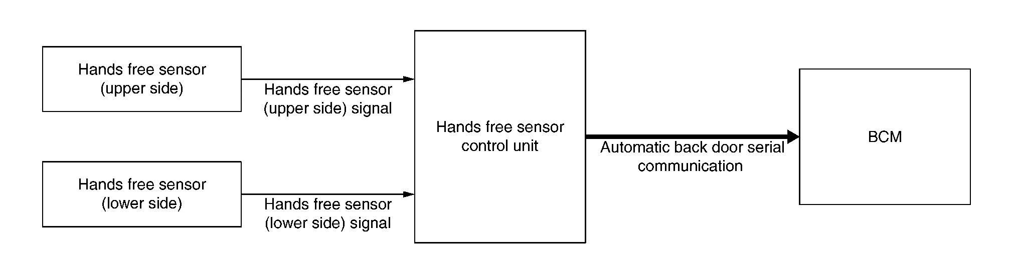
Hands Free Sensor Control Unit
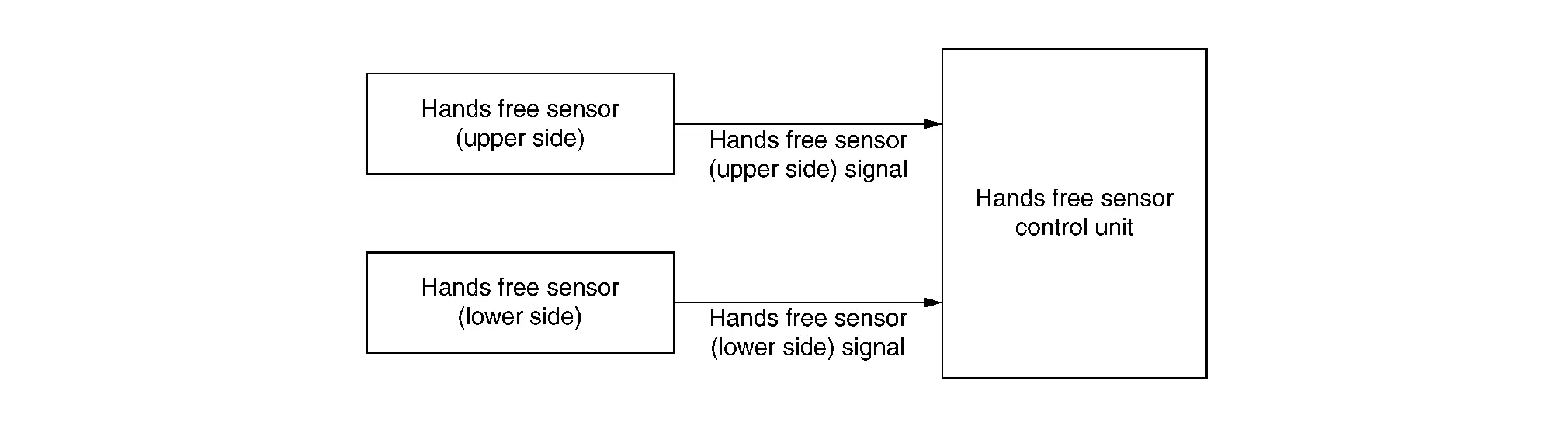
COMPONENT FUNCTION WITHIN SYSTEM
Only when hands free sensor (upper side) and hands free sensor (lower side) simultaneously detect that feet approach the sensors will the operation permission of the auto open/close function of the back door be judged.
INDIVIDUAL COMPONENT FUNCTION
Hands free sensor control unit judges user operation by detecting the voltage waveform change of hands free sensor (upper side) and hands free sensor (lower side). The hands free sensor control unit then transmits the automatic back door operation request signal to BCM via serial communication.
COMPONENT PARTS LOCATION
Hands free sensor control unit is installed in the rear bumper fascia. Refer to Component Parts Location.
Inside Key Antenna
COMPONENT FUNCTION WITHIN SYSTEM
Detects that Intelligent Key is within the inside detection area.
-
Inside key antenna
-
NATS antenna amp.

INDIVIDUAL COMPONENT FUNCTION
-
Transmits detection status to Intelligent Key unit.
-
Transmits request signal to Intelligent Key.
COMPONENT OPERATION
The Intelligent Key unit judges whether the Intelligent Key is detected within the detection range by the change of the inside key antenna signal (voltage waveform).
COMPONENT PARTS LOCATION
-
Push-button ignition switch (NATS antenna amp.) is installed in switch panel.
-
Inside key antenna is installed in behind the luggage rear plate. (Japan production models)
-
Inside key antenna is installed in behind the rear seat cushion. (USA production models)
For details: Refer to Component Parts Location.
Intelligent Key Unit
COMPONENT FUNCTION WITHIN SYSTEM
Intelligent Key unit controls the Intelligent Key system.

INDIVIDUAL COMPONENT FUNCTION
When the door request switch or Intelligent Key button is pressed, Intelligent Key unit transmits door lock/unlock request signal to BCM via CAN communication.
COMPONENT PARTS LOCATION
Intelligent Key unit is behind instrument pad B. Refer to Component Parts Location.
Intelligent Key Warning Buzzer
COMPONENT FUNCTION WITHIN SYSTEM
The Intelligent Key warning buzzer checks the operation of the Intelligent Key, the door request switch, notifies the user of the start of operations automatic back door system, and warns the user outside of the Nissan Ariya vehicle when they are operated inappropriately.
INDIVIDUAL COMPONENT FUNCTION
-
Operates when signal is received from Intelligent Key unit.
-
Notifies the user of the start of operations automatic back door system.
COMPONENT PARTS LOCATION
Intelligent Key warning buzzer is installed behind the rear bumper fascia. Refer to Component Parts Location.
Outside Key Antenna
COMPONENT FUNCTION WITHIN SYSTEM
Detects that Intelligent Key is within the outside detection area.
INDIVIDUAL COMPONENT FUNCTION
-
Transmits detection status to Intelligent Key unit.
-
Transmits request signal to Intelligent Key.
COMPONENT OPERATION
The outside key antenna detection area is in the range of approximately 0.8 m (31.50 in) surrounding the door request switch and back door request switch . However, this operating range depends on the ambient conditions.
COMPONENT PARTS LOCATION
-
Outside key antenna (rear door) are installed in backside of rear door finisher.
-
Outside key antenna (rear bumper) is installed in backside of rear bumper fascia.
-
For details: Refer to Component Parts Location.
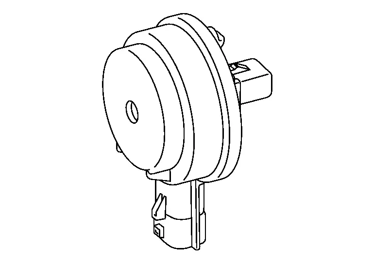
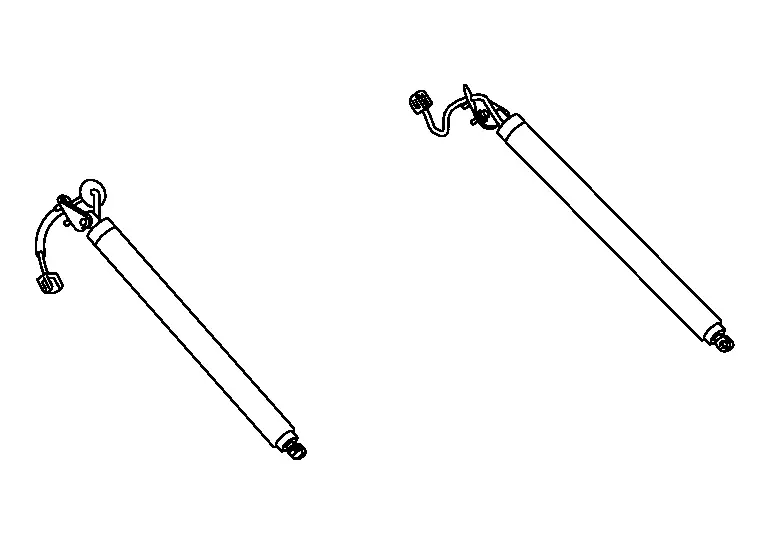
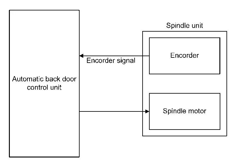
Spindle Unit
COMPONENT FUNCTION WITHIN SYSTEM
-
Encoder: Automatic back door control unit receives the pulse signals from encoders A and B that occurred due to synchronization with the back door operation. The automatic back door control unit calculates the back door position, operation direction, and operation speed according to the received pulse signals.
-
Spindle motor: Inputs open/close signal from automatic back door control unit and activates the automatic back door open/close operation.
INDIVIDUAL COMPONENT FUNCTION
Transmit encoder signal to automatic back door control unit.
COMPONENT PARTS LOCATION
Spindle unit installed in back door. Refer to Component Parts Location.
Touch Sensor
COMPONENT FUNCTION WITHIN SYSTEM
During back door close operation, the touch sensor detects any trapped foreign material.
INDIVIDUAL COMPONENT FUNCTION
Transmits touch sensor signal to automatic back door control unit.
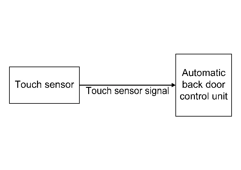
COMPONENT PARTS LOCATION
Touch sensor is installed in back door panel. Refer to Component Parts Location.
Other materials:
P2615 Intake Camshaft Position Sensor
DTC Description
DTC DETECTION LOGIC DTC
CONSULT screen terms
(Trouble diagnosis content)
DTC detection condition
P2615
00
A camshaft posi signal B1
(Camshaft A Position Signal Output Circuit Low Bank 1)
Diagnosis condition
Engine running at idle
Signal (terminal)
...
P11aa Vcr Position Learning
DTC Description
DTC DETECTION LOGIC DTC
CONSULT screen terms
(Trouble diagnosis content)
DTC detection condition
P11AA
00
VCR position learning
(Variable compression ratio position learning)
Diagnosis condition
Ignition switch ON
Signal (terminal)
—
Thresho ...
Symptom Diagnosis. Interior Lighting System Symptoms
Symptom Table
NOTE:
Perform self diagnosis result with CONSULT before the symptom diagnosis. Perform the trouble diagnosis if any DTC is detected.
Symptom Possible cause Inspection item
All the following lamps do not turn ON:
Map lamp assembly
Room lamp
Personal lamp
Lu ...