Nissan Rogue (T33) 2021-Present Service Manual: System Description :: Component Parts
Power Seat System
Component Parts Location

| No. | Component | Function |
|---|---|---|
| 1. | Sliding motor LH (RH similar) | Refer to Sliding Motor. |
| 2. | Power seat switch LH (RH similar) | Refer to Power Seat Switch. |
| 3. | Lifting motor LH | Refer to Lifting Motor LH. |
| 4. | Thigh support motor LH | Refer to Thigh Support motor LH. |
| 5. | Reclining motor LH (RH similar) | Refer to Reclining Motor. |
Power Seat Switch
-
The power seat switch is installed on the seat cushion outer finisher.

(Power seat switch LH shown, RH similar).
-
Built-in reclining switch, sliding switch and lifting switch, controls the power supplied to each power seat motor.
Sliding Motor
-
The sliding motor is installed to the seat frame assembly.
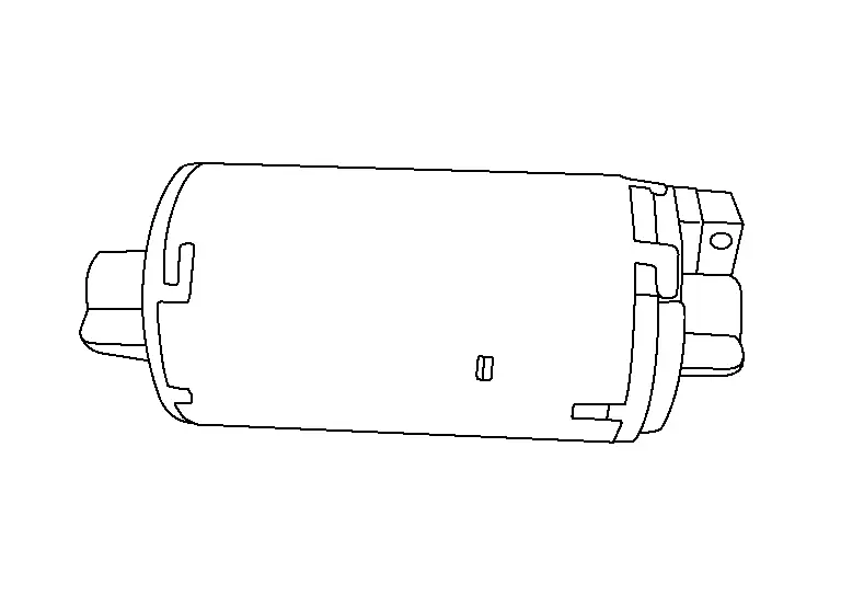
(Front seat LH shown, RH similar).
-
The seat is moved forward/backward by changing the rotation direction of the sliding motor.
Thigh Support motor LH
-
The thigh support motor LH is installed to the seat frame assembly.
-
The seat is moved upward/downward by changing the rotation direction of the thigh support motor LH.
Lifting Motor LH
-
The lifting motor LH is installed to the seat frame assembly.

-
The seat is moved upward/downward by changing the rotation direction of the lifting motor LH.
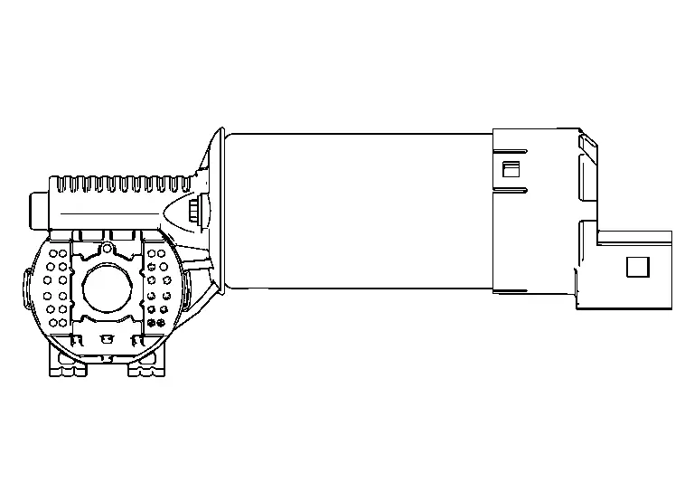
Reclining Motor
-
The reclining motor is installed to the seat back assembly.

(Front seat LH shown, RH similar).
-
The seat back is reclined forward/backward by changing the rotation direction of the reclining motor.
Lumbar Support System
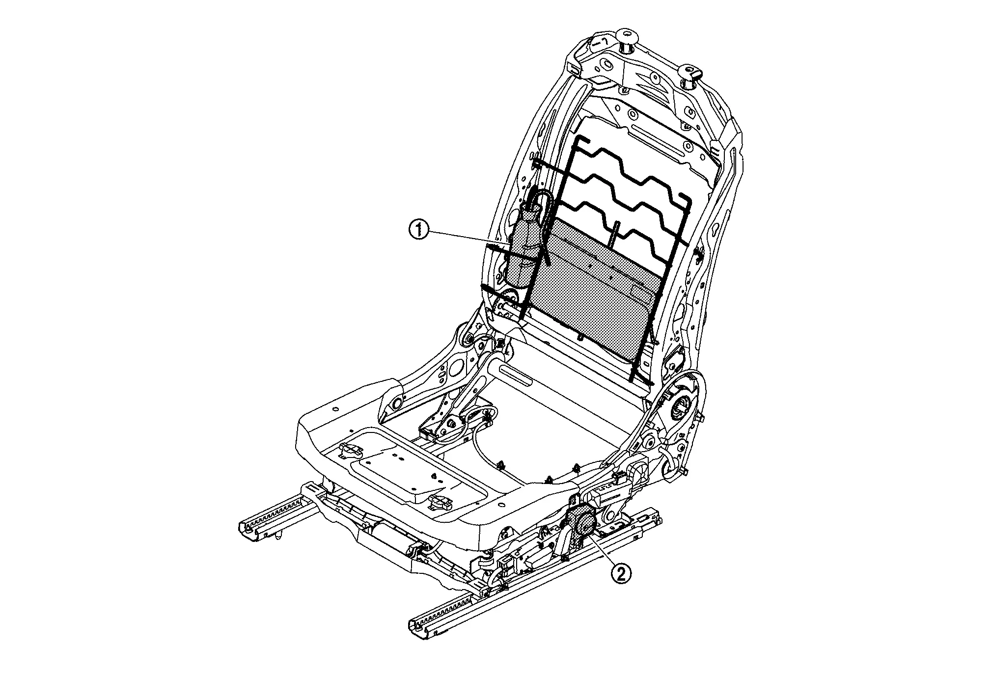
Component Parts Location
| No. | Component | Function |
|---|---|---|
| 1. | Pneumatic lumbar support unit | Refer to Pneumatic Lumbar Support Unit. |
| 2. | Lumbar support switch | Refer to Lumbar Support Switch. |
Pneumatic Lumbar Support Unit
-
The pneumatic lumbar support unit is installed on the seat back assembly.

-
With power supplied to the lumbar support switch, the pneumatic lumbar support unit operates the forward and backward position adjustment of the seat back support.
Lumbar Support Switch
-
The lumbar support switch is installed on the front seat cushion outer finisher.
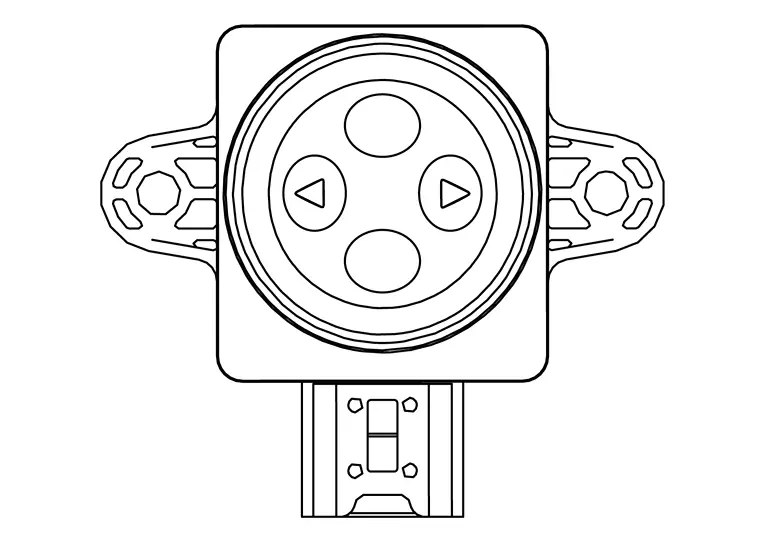
-
The lumbar support switch controls the power supplied to the pneumatic lumbar support unit.
Heated Seat System
Component Parts Location
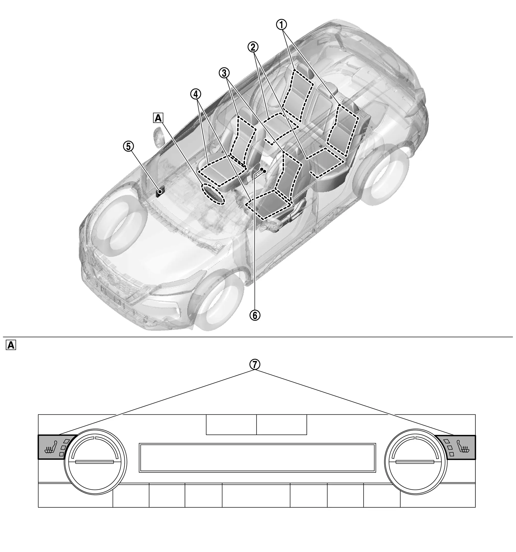
| A. | A/C switch assembly (view with A/C switch assembly removed) |
| No. | Component | Function |
|---|---|---|
| 1. | Rear seat back heater (if so equipped) | Refer to Rear Seat Heater. |
| 2. | Seat cushion heater (if so equipped) | |
| 3. | Front seat back heater | Refer to Front Seat Heater. |
| 4. | Seat cushion heater | |
| 5. | A/C amp. |
|
| 6. | Rear seat heater switch (if so equipped) | Refer to Rear Seat Heater Switch. |
| 7. | Front seat heater switch | Refer to Front Seat Heater Switch. |
Front Seat Heater
-
Front seat heater is installed in the seat cushion trim and seat back trim.
-
The seat heater consists of a seat back heater
 , seat cushion heater
  , heat sensor
  , CPU
, CPU  and thermostat
  , and controls the heated seat system.
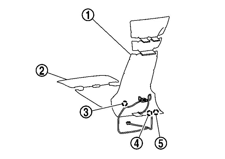
-
Controls the temperature of the front seat by turning the front seat heater ON/OFF using the signals transmitted from the A/C amp. via LIN communication.
-
Front seat heater consists of a CPU that controls the temperature of the front seat by turning the front seat heater ON/OFF.
Rear Seat Heater
-
Rear seat heater is installed in the rear seat cushion trim and rear seat back trim.

-
Controls the temperature of the rear seat by turning the rear seat heater ON/OFF using the signals transmitted from the A/C amp. via LIN communication.
-
Rear seat heater consists of a CPU that controls the temperature of the rear seat by turning the rear seat heater ON/OFF.
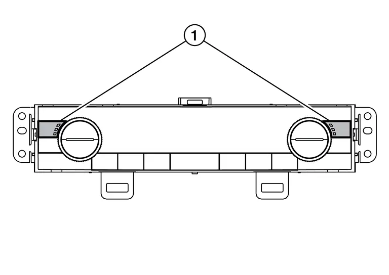
Front Seat Heater Switch
-
Front seat heater switch (1) is integrated with the A/C switch assembly.
-
A/C switch assembly transmits the front seat heater switch request signal to the A/C amp. via LIN communication.
-
A/C switch assembly receives the front seat heater switch indicator signal from the A/C amp. via LIN communication.
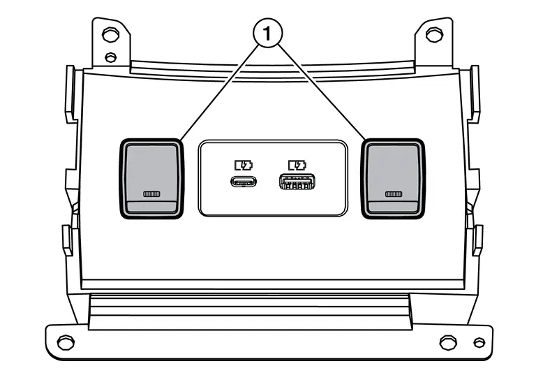
Rear Seat Heater Switch
-
Rear seat heater switch (1) is installed on the rear of the center console.
-
Rear seat heater switch transmits the rear seat heater switch request signal to the A/C switch assembly.
-
A/C switch assembly turns the rear seat heater switch indicator ON/OFF based on the signal received from the A/C amp. via LIN communication.
Other materials:
Basic information
The Nissan Rogue offers several Driver Assistance features that support the driver in different situations. Availability depends on vehicle equipment.
Forward Driving Aids
Automatic Emergency Braking (AEB) with Pedestrian Detection
Provides alerts and braking assistance when a forward collisi ...
Ivc Branch Line Circuit
Diagnosis Procedure
CHECK CONNECTOR
Turn the ignition switch OFF.
Disconnect the battery cable from the negative terminal.
Check the following terminals and connectors for damage, bend and loose connection (unit side and connector side).
TCU
8CH CAN gateway
Is the ...
P2251 Ho2s2
DTC Description
To judge malfunctions, the diagnosis checks that the A/F signal
computed by ECM from the A/F sensor 1 signal fluctuates according to
fuel feedback control.DTC DETECTION LOGIC DTC
CONSULT screen terms
(Trouble diagnosis content)
DTC detection condition
P2251
00
...