Nissan Rogue (T33) 2021-Present Service Manual: System Description :: System
Power Seat System
System Description
Power seat can be operated regardless of ignition switch status, because power supply is always supplied to the power seat switch.
SLIDING OPERATION
While operating the sliding switch located in the power seat switch, the sliding motor operates and makes seat forward and backward position adjustment possible.
RECLINING OPERATION
While operating the reclining switch located in the power seat switch, the reclining motor operates and makes seat back forward and backward position adjustment possible.
LIFTING OPERATION (FRONT SEAT LH)
While operating the lifting switch located in the power seat switch, the lifting motor LH operates and makes seat up and down position adjustment possible.
THIGH SUPPORT OPERATION (FRONT SEAT LH)
While operating the thigh support switch located in the power seat switch, the thigh support motor LH operates and makes seat cushion (front side) up and down position adjustment possible.
Lumbar Support System
System Description
-
Lumbar support can operate regardless of ignition switch status, because power supply is always supplied to the lumbar support switch.
-
While operating the lumbar support switch, the pneumatic lumbar support unit operates and makes forward and backward position adjustment of the seat back support possible.
Heated Seat System
System Description
SYSTEM DIAGRAM
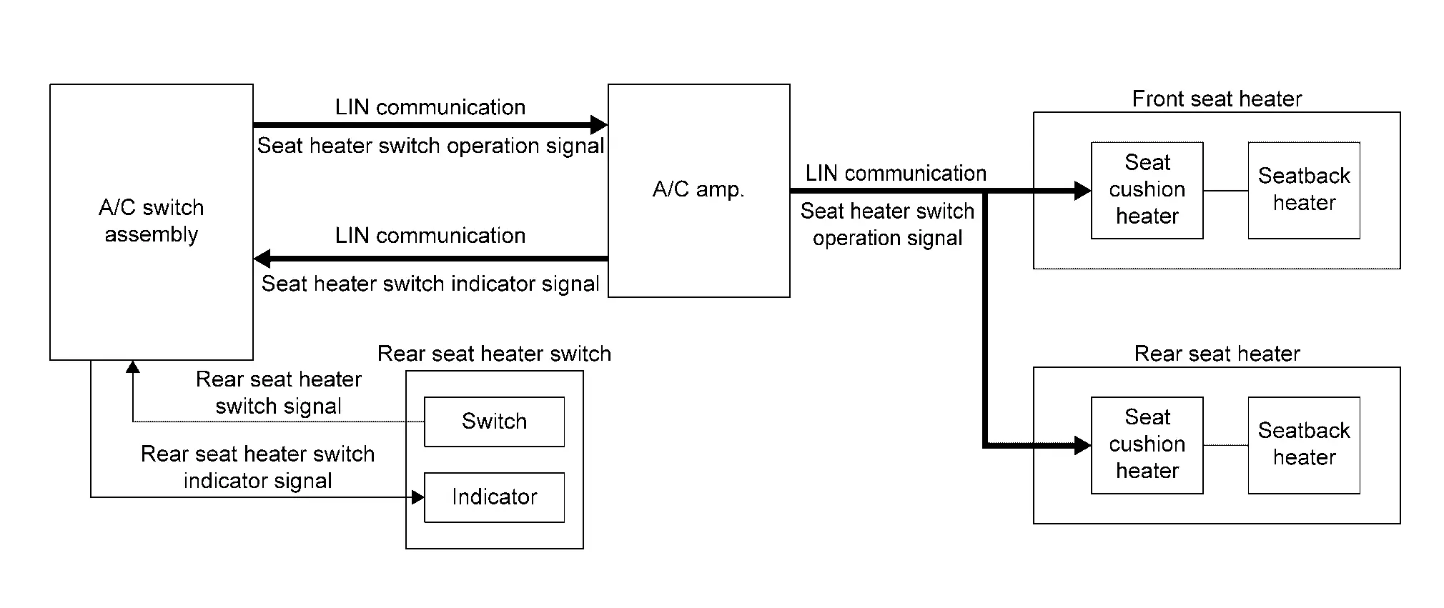
| Component | Function |
|---|---|
| A/C amp. | A/C amp. receives switch operation signals transmitted from the A/C switch assembly via LIN communication and transmits the switch operation signals to the seat heaters via LIN communication. |
| Front seat heater | Refer to Front Seat Heater. |
| Rear seat heater | Refer to Rear Seat Heater. |
| A/C switch assembly |
|
| Rear seat heater switch | Rear seat heater switch is used to turn the rear seat heaters ON/OFF and set the temperature (Low, Mid, or High). |
DESCRIPTION
-
Heated seat system is activated by the seat heater switch while the engine is running.
-
The seat heater temperature can be adjusted at 3 levels (Low, Mid, High) respective to the heating function by operating the seat heater switch.
-
The operation status of the heated seat system can be checked by checking the indicators of the seat heater switch.
OPERATION DESCRIPTION
-
When the front seat heater switch is operated, the A/C switch assembly recognizes switch operation.
-
When the rear seat heater switch is operated, the A/C switch assembly receives a switch operation signal.
-
The A/C switch assembly transmits a switch operation signal to A/C amp. via LIN communication.
-
When the A/C amp. receives a switch operation signal, it operates the heated seat system.
-
A/C amp. operates the heated seat system and simultaneously sends the switch indicator signal to the A/C switch assembly via LIN communication.
-
When the A/C switch assembly receives a switch indicator signal, it illuminates the indicator on the seat heater switch.
Heating Control
-
The seat cushion heater is integrated with a heat sensor that detects the seat temperature. The heat sensor transmits the seat temperature as the heat sensor signal to the CPU integrated with the seat cushion heater.
-
The CPU recognizes the seat temperature from heat sensor signal. It adjusts the seat temperature by stopping the operation when the seat temperature reaches the operation stop temperature
 , and starting operation when the seat temperature reaches the operation start temperature
  .
.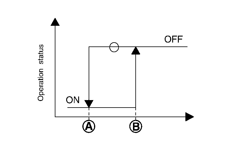
Preset temperature Temperature °F (°C) Temperature at operation stop Temperature at operation start Low 101.3 (38.5) 95.9 (35.5 ) Mid 104.9 (40.5) 99.5(37.5) High 108.5 (42.5) 103.1 (39.5)
Fail-safe
-
Seat heater equips fail-safe function.
-
When a malfunction occurs in the systems shown below, seat heater performs fail-safe control.
| Malfunction condition | Fail-safe | Reset condition |
|---|---|---|
| Seat heater output circuit short or open | Seat heater operation is suspended. | Ignition switch OFF |
| Heat sensor circuit short or open | Seat heater operation is suspended. | Ignition switch OFF |
| High temperature of the seat heater is detected by the heat sensor | Seat heater operation is suspended. | Ignition switch OFF |
| The thermostat integrated with the seat heater detects malfunction | Seat heater operation is suspended. | Ignition switch OFF |
| Seat heater output circuit short to the ground (detected 800 times) | All operations are suspended. | ― |
| The CPU integrated with the seat cushion heater is hot | All operations are suspended. | Ignition switch OFF |
| The data that configures the software of the CPU integrated with the seat cushion heater is in an abnormal condition | The program is initialized. | Ignition switch ON |
| The power supplied to the seat heater is in an abnormal condition (less than 8.5 V, or 16.5 V or more) | Seat heater operation are suspended. | Power supply is normalized (10.5 V - 15.5 V or less) |
| An abnormal LIN communication has occurred | Seat heater operation are suspended. | LIN communication is normalized |
Other materials:
Variable Compression Ratio Motor
Component Inspection
CHECK VCR MOTOR
Turn ignition switch OFF.
Disconnect VCR motor harness connector.
Check the continuity between VCR motor terminals as per the following.
VCR motor Continuity
Terminal
2
3
Existed
1
3
1
Check harness for short ...
Rear View Monitor. Preparation. Preparation
Preparation
Commercial Service Tools
Tool Description
Power tool
Loosening screws
...
B2720-11 Corner Sensor [rl]
DTC Description
DTC DETECTION LOGIC DTC CONSULT screen items (Trouble diagnosis content) DTC detection condition
B2720-11
CORNER SENSOR [RL]
(Corner sensor [rear left])
Diagnosis condition
When ignition switch is ON
Signal (terminal)
Rear sonar sensor signal LH outer
Th ...