Nissan Rogue (T33) 2021-Present Service Manual: System
Meter System
System Description
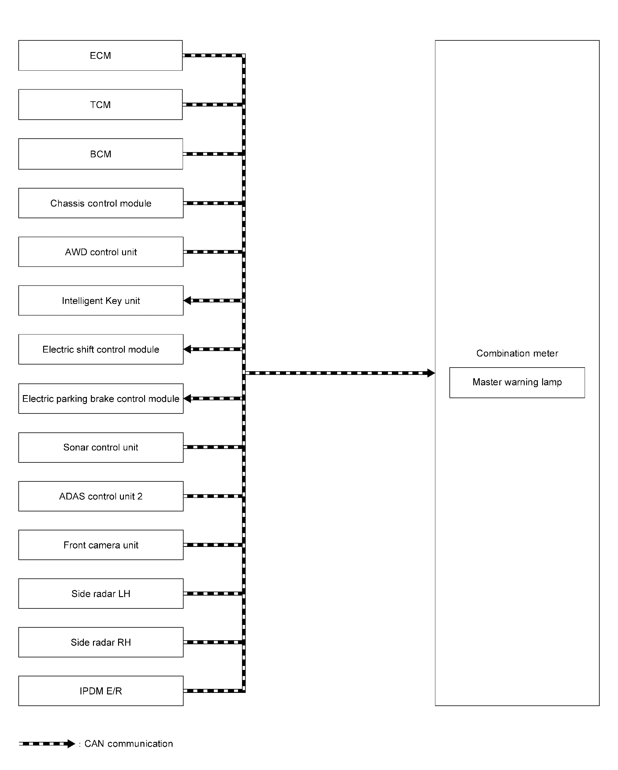
SYSTEM DIAGRAM
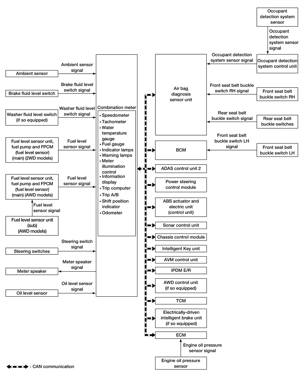
| Parts name | Description |
|---|---|
| Ambient sensor | Refer to Ambient Sensor. |
| BCM | Transmits the BCM status to the combination meter via CAN communication. |
| Combination meter | Refer to Combination Meter. |
| ECM | Transmits the ECM status to the combination meter via CAN communication. |
| Fuel Level Sensor Unit, Fuel Pump and FPCM (Fuel Level Sensor)(Main) - 2WD Models | Refer to Fuel Level Sensor Unit, Fuel Pump and FPCM (Fuel Level Sensor) (Main) - 2WD Models. |
| Fuel Level Sensor Unit, Fuel Pump and FPCM (Fuel Level Sensor)(Main) and Fuel Level Sensor Unit (Sub) - AWD Models | Refer to Fuel Level Sensor Unit, Fuel Pump and FPCM (Fuel Level Sensor) (Main) and Fuel Level Sensor Unit (Sub) - AWD Models. |
| Illumination control switch | Refer to Illumination Control Switch. |
| Meter speaker | Refer to Meter Speaker. |
| TCM | Transmits the TCM status to the combination meter via CAN communication. |
| Steering switches | Refer to Steering Switches. |
Combination Meter Input Signal (CAN Communication Signal)
| Transmit unit | Signal name |
|---|---|
| BCM | Buzzer output signal |
| Dimmer signal | |
| Door switch signal | |
| Front fog light status signal | |
| High beam assist indicator signal | |
| High beam status signal | |
| Light reminder warning signal | |
| Low beam status signal | |
| Low tire pressure warning lamp signal | |
| Low tire pressure wheel location signal | |
| Position light status signal | |
| Seat belt buckle switch (front LH) signal | |
| Sleep wake up signal | |
| TPMS malfunction warning lamp signal | |
| ECO advice signal | |
| TCM | Shift position signal |
| CVT warning message signal | |
| Electric shift warning message signal | |
| Electric shift warning lamp signal | |
| Shift P range request display signal | |
| Shift refuse buzzer signal | |
| Neutral hold mode signal | |
| ECM | Battery warning request signal (ECM) |
| ECO mode indicator signal | |
| ECO pedal guide signal | |
| Engine coolant temperature signal | |
| Engine oil pressure warning lamp signal | |
| Engine speed signal | |
| Engine status signal | |
| Fuel consumption monitor signal | |
| Remaining distance signal | |
| Nissan Ariya Vehicle speed display signal | |
| Power steering control module | Power steering warning lamp signal |
| ADAS control unit 2 | Buzzer output signal |
| Meter display signal | |
| AEB warning lamp signal | |
| RAB warning lamp signal | |
| Air bag diagnosis sensor unit | Occupant detection signal |
| SRS air bag warning lamp signal | |
| Seat belt buckle switch (rear) signal | |
| Seat belt warning (front RH) signal | |
| IPDM E/R | Battery warning request signal (IPDM E/R) |
| Headlamp warning signal | |
| Starter relay status signal | |
| Intelligent Key unit | Buzzer output signal |
| Meter display signal | |
| Chassis control module | Meter display signal |
| Automatic brake hold indicator lamp signal | |
| Drive mode signal | |
| Around view monitor control unit | Buzzer output signal |
| MOD setting status signal | |
| Sonar control unit | Parking sensor error signal |
| Sonar indicator signal | |
| ABS actuator and electric unit (control unit) | ABS warning lamp signal |
| Brake warning lamp signal | |
| Buzzer output signal | |
| Electric parking brake indicator lamp signal | |
| Electric parking brake warning lamp signal | |
| Electric parking brake status signal | |
| Odometer signal | |
| VDC OFF indicator lamp signal | |
| VDC warning lamp signal | |
| AWD control unit | AWD warning display signal |
| Torque distribution indicator signal | |
| Driver seat control unit | Memory guidance display request signal |
DESCRIPTION
Combination Meter
-
The combination meter receives necessary signals from each unit, switch, and sensor to control the following functions.
-
Measuring instruments
-
Speedometer
-
Tachometer
-
Engine coolant temperature gauge
-
Fuel gauge
-
Odometer
-
Distance to empty
-
Clock
-
Ambient temperature
-
-
Warning lamps
-
Indicator lamps
-
Meter illumination control
-
Meter effect function
-
Information display
-
-
The combination meter incorporates a chime function that sounds an audible alarm with the meter speaker. For further details, refer to Combination Meter
. -
The combination meter includes an on board diagnosis function.
-
The combination meter can be diagnosed with CONSULT.
METER CONTROL FUNCTION LIST
| System | Description | Reference | |||
|---|---|---|---|---|---|
| Measuring instruments | Speedometer | Indicates Nissan Ariya vehicle speed. | System Description | ||
| Tachometer | Indicates engine speed. | System Description | |||
| Engine coolant temperature gauge | Indicates engine coolant temperature. | System Description | |||
| Fuel gauge | Indicates fuel level. | System Description | |||
| Odometer | Indicates the mileage. | System Description | |||
| Distance to empty | Indicates distance to empty. | System Description | |||
| Clock | Indicates current time. | System Description | |||
| Ambient temperature | Indicates ambient temperature. | System Description | |||
| Warning lamp/indicator lamp | The warning lamp/indicator lamp turns ON or turns OFF, according to system malfunction or Nissan Ariya vehicle condition. | Design | |||
| Meter illumination control | Meter illumination control function | Switch back and forth between daytime mode and night mode, according to a light switch position. | System Description | ||
| Back light illumination control function | The operation of the illumination control switch allows the brightness adjustment of meter illumination. | ||||
| Meter effect function | Engine-start effect function | Meter illumination at ignition switch ON from OFF to produce illumination effects. | System Description | ||
| Information display | The Information display displays status, according to system malfunction or Nissan Ariya vehicle condition. | System Description | |||
Speedometer
System Description
SYSTEM DIAGRAM
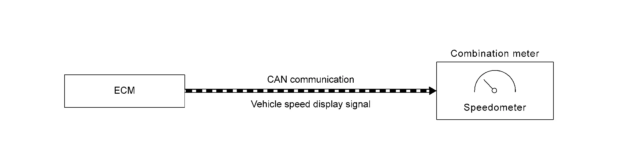
DESCRIPTION
-
The ECM transmits a vehicle speed display signal to the combination meter via CAN communication.
-
The combination meter indicates a Nissan Ariya vehicle speed to the speedometer, based on the vehicle speed display signal received from the ECM.
Tachometer
System Description
SYSTEM DIAGRAM

DESCRIPTION
-
ECM converts the pulse signal provided by the crankshaft position sensor to an engine speed signal and transmits it to the combination meter via CAN communication.
-
The combination meter indicates the engine speed to the tachometer according to the engine speed signal received via CAN communication.
Engine Coolant Temperature Gauge
System Description
SYSTEM DIAGRAM
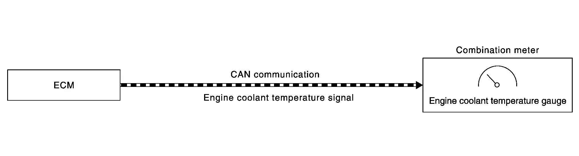
DESCRIPTION
-
ECM reads the engine coolant temperature signal from the engine coolant temperature sensor and transmits the signal to the combination meter via CAN communication.
-
The combination meter indicates the engine coolant temperature to the engine coolant temperature gauge according to the engine coolant temperature signal received via CAN communication.
Fuel Gauge
System Description
SYSTEM DIAGRAM
2WD Models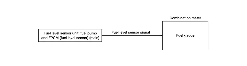
AWD Models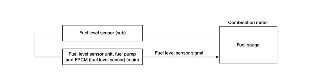
DESCRIPTION
Control Outline
The combination meter reads the fuel level sensor signal from the fuel level sensor unit and indicates the fuel level to the fuel gauge.
Refuel Control
The combination meter accelerates the fuel gauge if the all conditions listed below are met, or the ignition switch is ON from OFF.
-
Ignition switch is ON position.
-
The vehicle is not moving.
-
The fuel level change by 4
 (7/8 Imp gal) or more.
Odometer
System Description
SYSTEM DIAGRAM
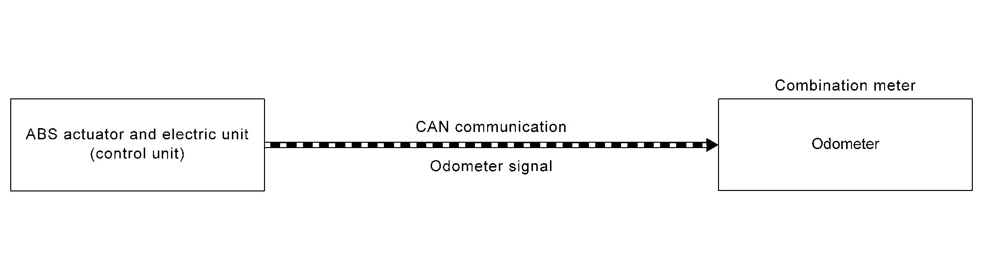
DESCRIPTION
The combination meter calculates mileage, based on the following signals and displays the mileage on the information display.
| Signal name | Signal path |
|---|---|
| Ignition signal | ŌĆö |
| Odometer signal | ABS actuator and electric unit (control unit)  Combination meter Combination meter |
Indication Range
| Odometer | 0 km - 999999 km |
Distance to Empty
System Description
SYSTEM DIAGRAM
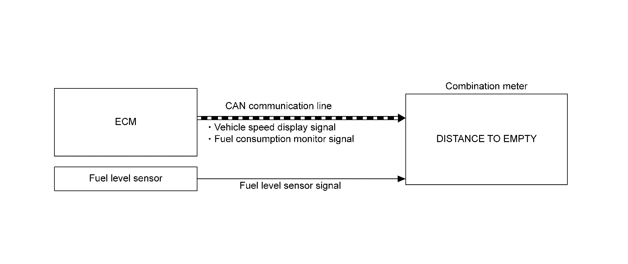
DESCRIPTION
The combination meter calculates distance to empty based on the following signals, and the calculated value is displayed on the information display.
| Signal name | Signal source |
|---|---|
| Ignition signal | ŌĆö |
| Fuel level sensor signal | Fuel level sensor unit  Combination meter Combination meter |
| Fuel consumption monitor signal | ECM Combination meter |
| Nissan Ariya Vehicle speed display signal | ECM Combination meter |
 NOTE:
NOTE:
-
Distance to empty on the information display is updated approximately every 30 seconds.
-
When the ignition switch is placed ON right after battery removal and installation, ŌĆ£ŌłÆŌłÆŌłÆŌĆØ is displayed until after a travel of 30 seconds.
-
The indicated values may not match each other when refueling with the ignition switch ON.
Ambient Temperature
System Description
SYSTEM DIAGRAM
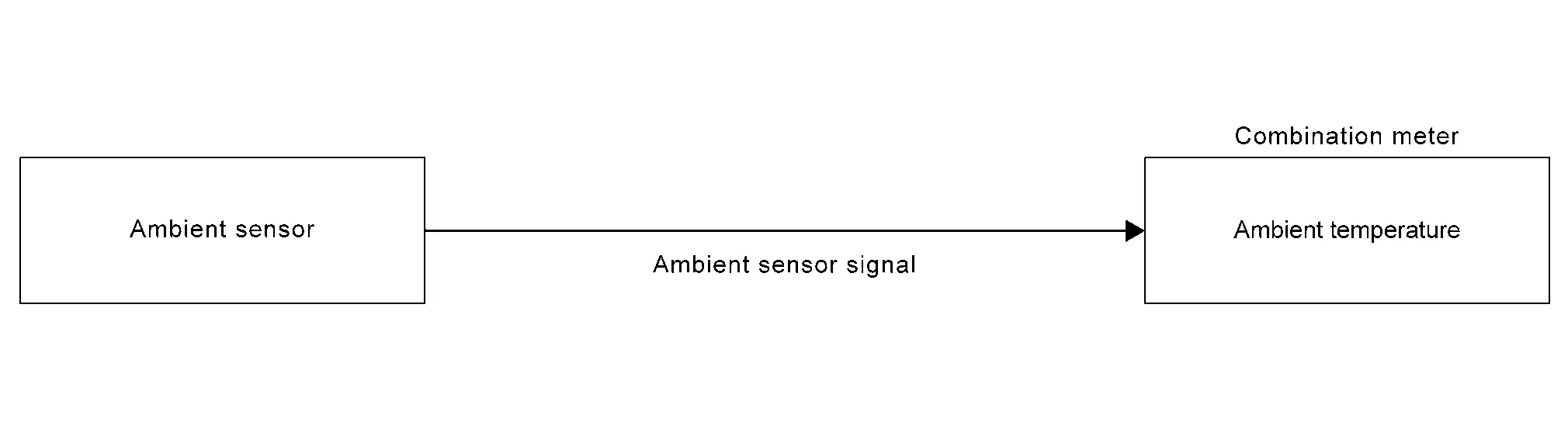
DESCRIPTION
The combination meter calculates ambient temperature based on the following signals, and the calculated value is displayed on the information display.
| Signal name | Signal path |
|---|---|
| Ignition signal | ŌĆö |
| Ambient sensor signal | Ambient sensor Combination meter |
| Nissan Ariya Vehicle speed display signal | ECM Combination meter |
NOTE:
-
The indicated temperature is corrected based on an ignition signal, ambient temperature detected by the ambient sensor, and Nissan Ariya vehicle speed signal. The indicated temperature is not raised under vehicle speed less than 20 km/h (12 MPH).
-
The ambient sensor input value that is displayed on ŌĆ£Data MonitorŌĆØ of CONSULT is the value before the correction. It may not match the indicated temperature on the information display.
-
Depending on engine heat or heat on the road surfaces, an ambient temperature may be indicated higher than actual one.
Clock
System Description
SYSTEM DIAGRAM
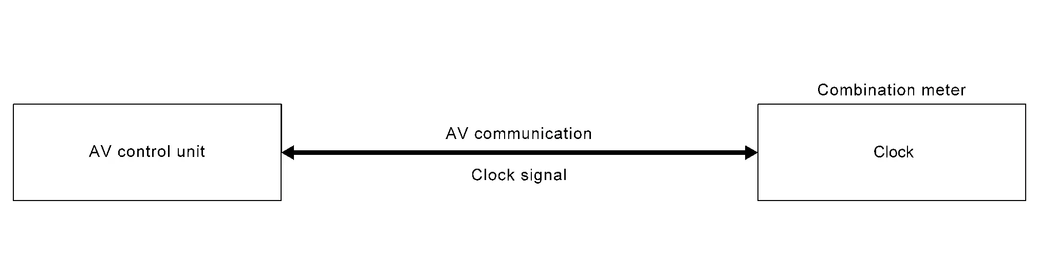
DESCRIPTION
The combination meter calculates time and displays it on the information display.
NOTE:
The settings screen of the information display allows the selection of time indication between 12-hour and 24-hour formats.
Warning Lamps/indicator Lamps
12V Battery Charge Warning Lamp
DESIGN/PURPOSE
12V battery charge warning lamp warns the driver for the unexpected power generation.

BULB CHECK
For 2 seconds after placing the ignition switch ON.
SYNCHRONIZATION WITH MASTER WARNING LAMP
Not applicable
OPERATION AT COMBINATION METER CAN COMMUNICATION CUT-OFF OR UNUSUAL SIGNAL
For actions on CAN communications blackout in the combination meter, refer to Fail-Safe.
SYSTEM DIAGRAM
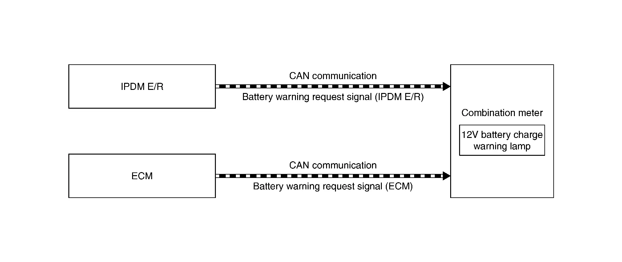
SIGNAL PATH
-
ECM transmits battery warning request signal (ECM) to combination meter via CAN communication when overvoltage or low voltage is detected on battery positive terminal or generator malfunction.
-
IPDM E/R transmits battery warning request signal (IPDM E/R) to combination meter via CAN communication when overvoltage or low voltage is detected on battery positive terminal.
-
Combination meter indicates 12V battery charge warning lamp judged with battery warning request signal received from ECM or IPDM E/R.
LIGHTING CONDITION
When any of the following symptoms occur while generator is operating:
-
Communication between generator and ECM is malfunction detected.
-
Communication between combination meter and ECM is malfunction detected.
-
Communication between combination meter and IPDM E/R is malfunction detected.
-
Generator detected internal malfunction.
-
Overvoltage detected on battery positive terminal.
-
Low voltage detected on battery positive terminal.
SHUTOFF CONDITION
Ignition switch is OFF.
ABS Warning Lamp
DESIGN/PURPOSE
The ABS warning lamp warns the driver of a malfunction in the ABS function or EBD function of ABS actuator and electric unit (control unit).
-
For USA

-
Except for USA
NOTE:
The ABS warning lamp may turn ON simultaneously with the brake warning lamp, VDC warning lamp. For details, refer to System Description.
BULB CHECK
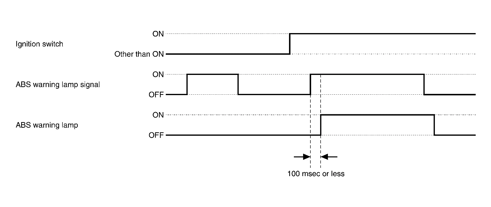
The ABS warning lamp turns ON and stays ON for 1 second after placing the ignition switch ON.
SYNCHRONIZATION WITH MASTER WARNING LAMP
Not applicable
OPERATION AT COMBINATION METER CAN COMMUNICATION CUT-OFF OR UNUSUAL SIGNAL
For actions on CAN communications blackout in the combination meter. Refer to Fail-Safe.
SYSTEM DIAGRAM
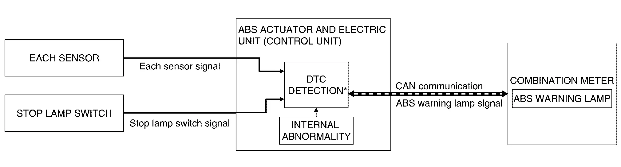
*: For DTCs that the ABS warning lamp turns ON. Refer to DTC Index.
SIGNAL PATH
-
The ABS actuator and electric unit (control unit) transmits an ABS warning lamp signal to the combination meter via CAN communication when detecting a malfunction.
-
The combination meter turns ON the ABS warning lamp when receiving an ABS warning lamp signal.
-
For the relationship between warning lamp and DTC. Refer to DTC Index.
LIGHTING CONDITION
The warning lamp turns ON when:
-
A malfunction is detected in the ABS function or EBD function of the ABS actuator and electric unit (control unit).
-
For the relationship between warning lamp and DTC. Refer to DTC Index.
SHUTOFF CONDITION
-
When the condition listed below is satisfied while the ignition switch ON:
-
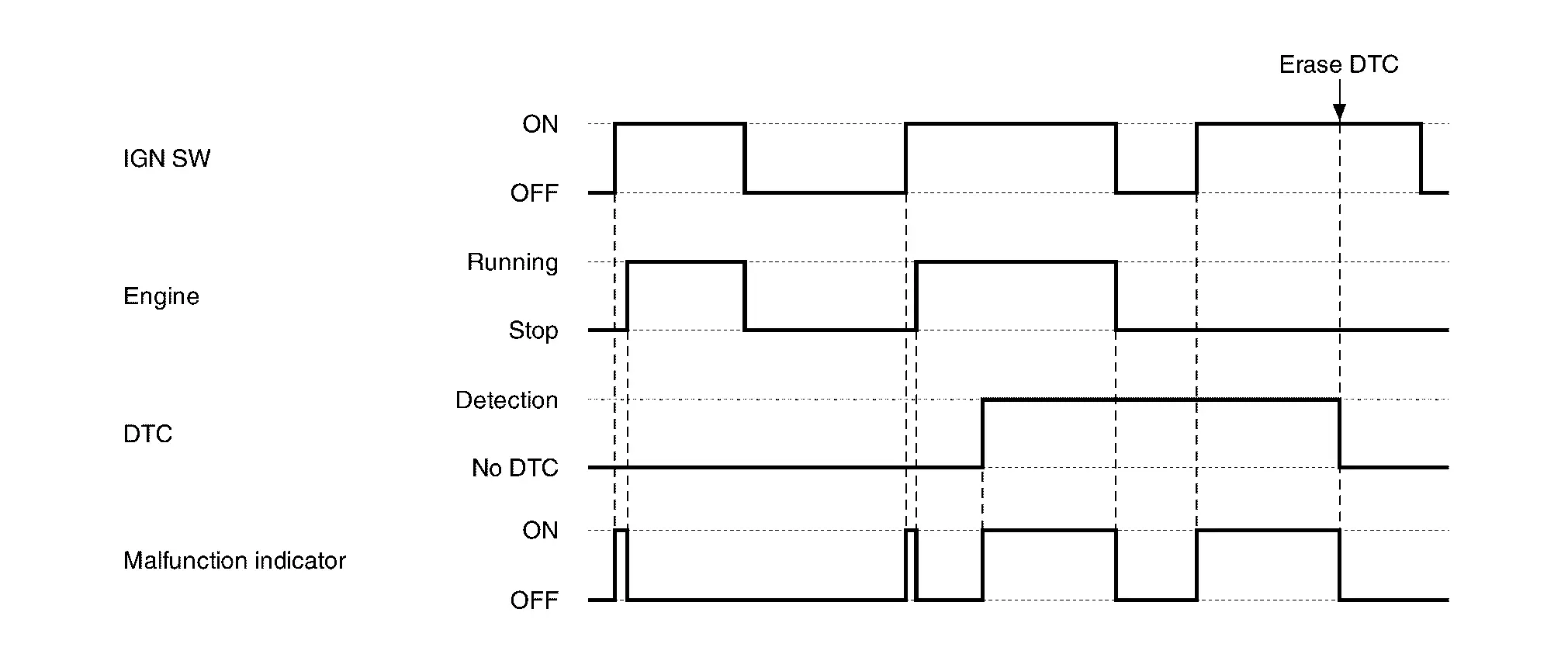
Erase DTC
-
-
The ignition switch is in a position other than ON.
TIMING CHART
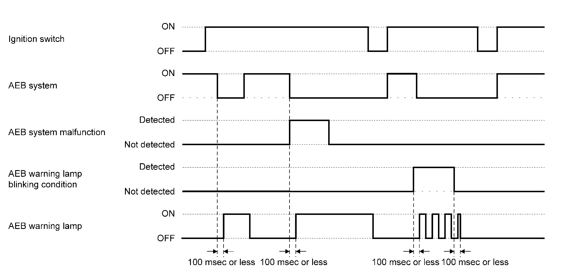
AEB Warning Lamp
DESIGN/PURPOSE
-
The AEB warning lamp warns the driver that AEB system is OFF.
-
The AEB warning lamp warns the driver of a malfunction in the AEB system.
BULB CHECK
AEB warning lamp turns ON after placing the ignition switch ON.
SYNCHRONIZATION WITH MASTER WARNING LAMP
Not applicable
OPERATION AT COMBINATION METER CAN COMMUNICATION CUT-OFF OR UNUSUAL SIGNAL
For actions on CAN communications blackout in the combination meter, refer to Fail-Safe.
SYSTEM DIAGRAM

SIGNAL PATH
-
The ADAS control unit 2 receives a system selection signal from the combination meter via CAN communication when AEB system ON is not selected.
-
The ADAS control unit 2 transmits an AEB warning lamp signal to the combination meter via CAN communication when detecting a malfunction or AEB system ON is not selected.
-
The combination meter turns ON the AEB warning lamp when receiving an AEB warning lamp signal.
LIGHTING CONDITION
-
When any of the following conditions, the AEB warning lamp illuminates:
-
An abnormal condition is present in the AEB system
-
The AEB system is turned OFF
-
-
When any of the following conditions, the AEB warning lamp blinks:
-
The distance sensor area of the front of the Nissan Ariya vehicle is covered with dirt or is obstructed
-
The interior temperature of the vehicle is extremely high
-
The windshield is dirty, frosted, fogged up, or damaged in front of the front camera unit
-
The front camera unit or the front camera unit bracket is not mounted properly
-
SHUTOFF CONDITION
When any of the following conditions, the AEB warning lamp is turned OFF:
-
The AEB system is turned ON.
-
The DTC is deleted.
-
The condition is improved.
-
The ignition switch is in a position other than ON.
TIMING CHART
Automatic Brake Hold Indicator Lamp
DESIGN/PURPOSE
-
Notifies the driver that automatic brake hold function can be operated (in the standby state). (white)

-
Notifies the driver that automatic brake hold function is applied. (green)
BULB CHECK
Not applicable
SYNCHRONIZATION WITH MASTER WARNING LAMP
Not applicable
OPERATION AT COMBINATION METER CAN COMMUNICATION CUT-OFF OR UNUSUAL SIGNAL
For actions on CAN communications blackout in the combination meter. Refer to Fail-Safe.
SYSTEM DIAGRAM
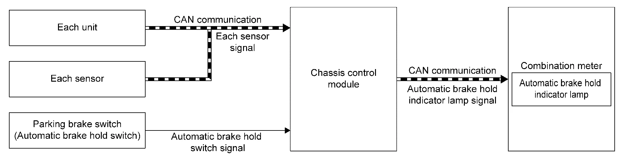
SIGNAL PATH
Automatic Brake Hold Function Standby State (Automatic Brake Hold Indicator Lamp: White)
-
Chassis control module receives automatic brake hold switch signal from automatic brake hold switch.
-
Chassis control module functions are turned ON by automatic brake hold switch signal. If the conditions to enter the standby state are satisfied, the module transmits automatic brake hold indicator lamp signal to combination meter via CAN communication.
-
Once receiving the automatic brake hold indicator lamp signal, the combination meter turns ON the automatic brake hold indicator lamp (white).
Automatic Brake Hold Function Operating State (Automatic Brake Hold Indicator Lamp: Green)
-
If the operating conditions are satisfied and automatic brake hold function operates when automatic brake hold indicator lamp (white) is turned ON, chassis control module transmits automatic brake hold indicator lamp signal to combination meter via CAN communication.
-
Once receiving the automatic brake hold indicator lamp signal, the combination meter turns ON the automatic brake hold indicator lamp (green).
Automatic Brake Hold Function Release
-
If an automatic brake hold function operation is canceled by a starting operation by the driver, chassis control module transmits automatic brake hold indicator lamp signal to combination meter via CAN communication.
-
Once receiving the automatic brake hold indicator lamp signal, the combination meter turns ON the automatic brake hold indicator lamp (white).
LIGHTING CONDITION
Automatic Brake Hold Indicator Lamp (White)
-
All of the following conditions are satisfied (standby state)
-
Ignition switch ON
-
Automatic brake hold switch ON(automatic brake hold switch indicator is turn ON)
-
Automatic brake hold function not operated
-
Driver seat belt is fastened
-
Electric parking brake is release
-
Shift position is not in the P
-
-
Automatic brake hold function operation is canceled by starting operation by the driver
Automatic Brake Hold Indicator Lamp (Green)
Automatic brake hold function applied
SHUTOFF CONDITION
-
When any of the condition listed below is satisfied while the ignition switch ON
-
Automatic brake hold switch is OFF (automatic brake hold switch indicator is turn OFF)
-
Driver seat belt is not fastened
-
Electric parking brake operated
-
-
Ignition switch OFF
-
Shift position is in the P
-
Door (driver side) is opened.
TIMING CHART
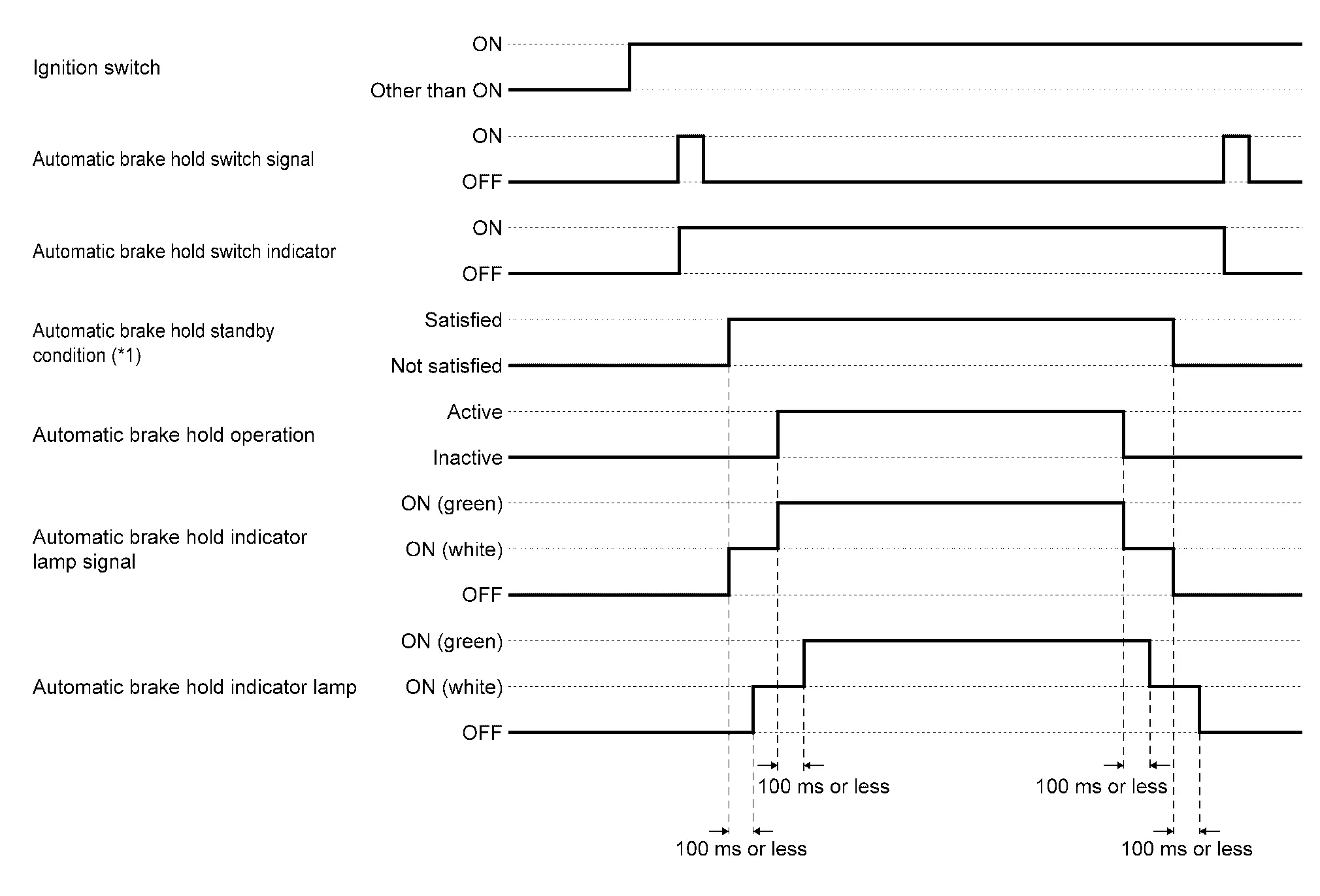
*1: For standby conditions of automatic brake hold function. Refer to System Description.
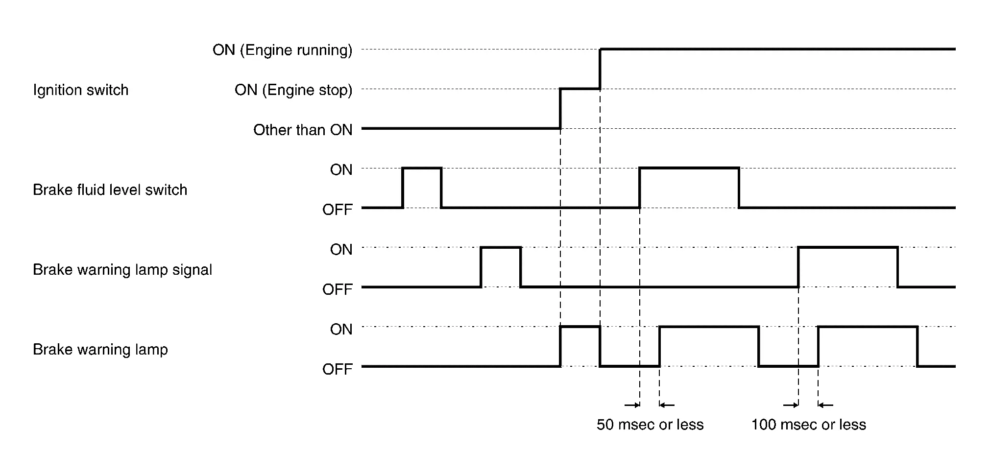
Brake Warning Lamp
DESIGN/PURPOSE
-
The brake warning lamp warns the driver of brake fluid shortages.
-
For USA

-
Except for USA

-
-
The brake warning lamp warns the driver of a malfunction in the EBD function of ABS actuator and electric unit (control unit).
NOTE:
The brake warning lamp may turn ON simultaneously with the ABS warning lamp, VDC warning lamp. For details. Refer to System Description.
BULB CHECK
The brake warning lamp turns ON and stays ON for 2 second after placing the ignition switch ON.
SYNCHRONIZATION WITH MASTER WARNING LAMP
Not applicable
SYNCHRONIZATION WITH WARNING CHIME
Not applicable
OPERATION AT COMBINATION METER CAN COMMUNICATION CUT-OFF OR UNUSUAL SIGNAL
For actions on CAN communications blackout in the combination meter. Refer to Fail-Safe.
SYSTEM DIAGRAM
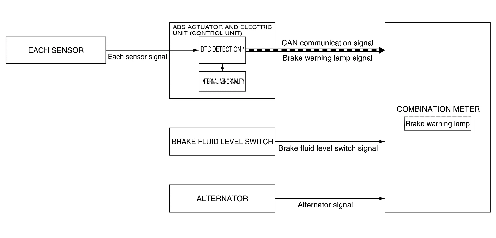
*: For DTCs that the brake warning lamp turns ON. Refer to DTC Index.
SIGNAL PATH
When Brake Fluid Is Insufficient
The combination meter turns ON/OFF the brake warning lamp, according to the ON/OFF state of the brake fluid level switch.
When The EBD Function Is In Abnormal State
-
The ABS actuator and electric unit (control unit) transmits a brake warning lamp signal to the combination meter via CAN communication when detecting a malfunction in the EBD function.
-
The combination meter turns ON the brake warning lamp when receiving a brake warning lamp signal.
-
For the relationship between warning lamp and DTC. Refer to DTC Index.
When The Brake Vacuum Sensor System Is In Abnormal State
-
The ABS actuator and electric unit (control unit) transmits a brake warning lamp signal to the combination meter via CAN communication when detecting a malfunction in the brake vacuum sensor system.
-
The combination meter turns ON the brake warning lamp when receiving a brake warning lamp signal.
-
For the relationship between warning lamp and DTC. Refer to DTC Index.
LIGHTING CONDITION
When any of the condition listed below is satisfied while the engine is running:
-
Brake fluid level switch ON.
-
A malfunction is detected in the EBD function of the ABS actuator and electric unit (control unit).
-
A malfunction is detected in the brake vacuum sensor system.
-
For the relationship between warning lamp and DTC. Refer to DTC Index.
SHUTOFF CONDITION
-
When the condition listed below is satisfied while the ignition switch ON:
-
Brake fluid level switch is OFF.
-
When EBD function of the ABS actuator and electric unit (control unit) is normal.
-
When brake vacuum sensor system is normal.
-
Erase DTC
-
-
The ignition switch is in a position other than ON (engine stop).
TIMING CHART
Dipped Beam Indicator Lamp
DESIGN/PURPOSE
Dipped beam indicator lamp informs the driver that headlamp (LO) is in ON status.

BULB CHECK
Not applicable
SYNCHRONIZATION WITH MASTER WARNING LAMP
Not applicable
OPERATION AT COMBINATION METER CAN COMMUNICATION CUT-OFF OR UNUSUAL SIGNAL
For actions on CAN communications blackout in the combination meter. Refer to Fail-Safe.
SYSTEM DIAGRAM

SIGNAL PATH
-
BCM transmits low beam status signal to combination meter via CAN communication.
-
When combination meter receives low beam status signal, combination meter turns dipped beam indicator lamp ON.
LIGHTING CONDITION
When headlamp (LO) is turned ON.
SHUTOFF CONDITION
When headlamp (LO) is turned OFF.
Electric Parking Brake Indicator Lamp
DESIGN/PURPOSE
-
The electric parking brake indicator lamp warns the driver that the parking brake is engaged.
-
For USA

-
Except for USA

-
-
The electric parking brake indicator lamp warns the driver of a malfunction in the electric parking brake system.
BULB CHECK
Applicable
SYNCHRONIZATION WITH MASTER WARNING LAMP
Applicable
OPERATION AT COMBINATION METER CAN COMMUNICATION CUT-OFF OR UNUSUAL SIGNAL
For actions on CAN communications blackout in the combination meter. Refer to Fail-Safe.
SYSTEM DIAGRAM
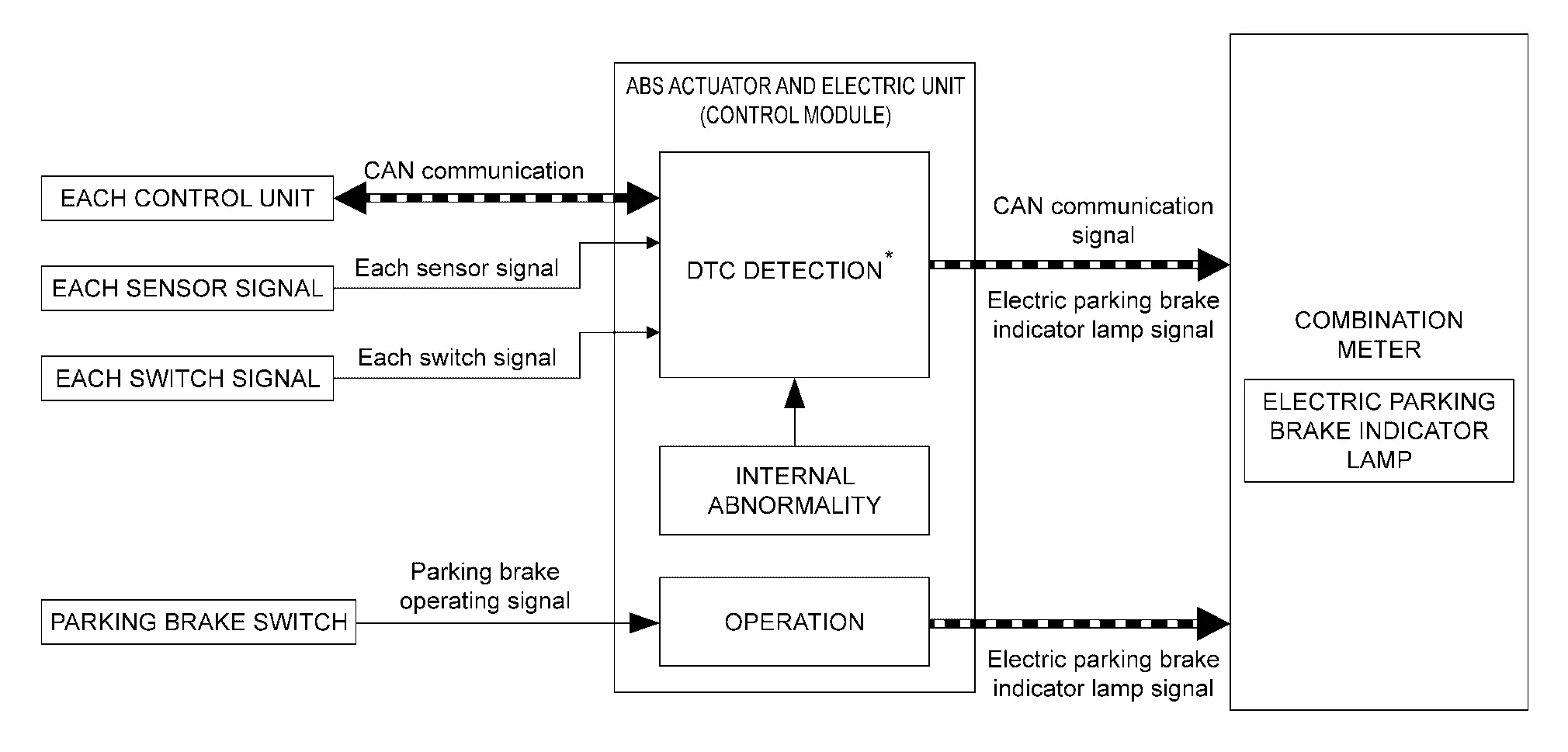
*: For DTCs that the electric parking brake indicator lamp turns ON. Refer to DTC Index.
SIGNAL PATH
When Operating The Parking Brake
-
The ABS actuator and electric unit (control unit) receives a parking brake switch operation signal from the parking brake switch is pulling.
-
The ABS actuator and electric unit (control unit) transmits a electric parking brake indicator lamp signal to the combination meter via CAN communication according to the received electric parking brake indicator lamp signal.
-
The combination meter turns ON the electric parking brake indicator lamp when receiving a electric parking brake indicator lamp signal.
When The Electric Parking Brake System Is In Abnormal State (Blinking)
-
The ABS actuator and electric unit (control unit) transmits a electric parking brake indicator lamp signal to the combination meter via CAN communication when detecting a malfunction (following condition) in the electric parking brake system.
-
When a status cannot be judged between applied and released.
-
When the parking brake switch is operated under the condition that the parking brake switch is malfunction.
-
When the parking brake switch is operated under the condition that the parking brake actuator is malfunction.
-
When the initial position adjustment of the parking brake actuator is incomplete.
-
-
The combination meter blinking the electric parking brake indicator lamp when receiving a electric parking brake indicator lamp signal.
-
For the relationship between indicator lamp and DTC. Refer to DTC Index.
LIGHTING CONDITION
When any of the condition listed below is satisfied.
-
Electric parking brake is engaged.
-
When the parking brake switch is pulled while driving the Nissan Ariya vehicle, resulting in parking brake activation.
-
While measuring braking force.
-
For the relationship between warning lamp and DTC. Refer to DTC Index.
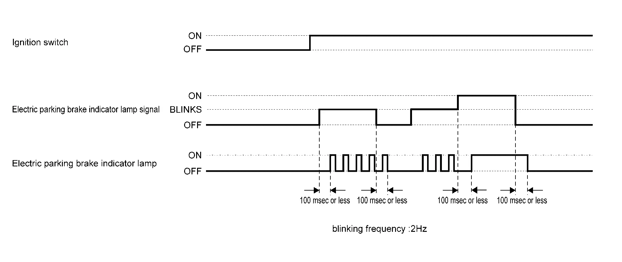
BLINKING CONDITION
-
When any of the condition listed below is satisfied.
-
The combination meter not receives a signal from ABS actuator and electric unit (control unit) via CAN communication.
-
When the electric parking brake system is not activated. (Unable to judge malfunction)
-
When the parking brake switch is operated under the condition that the parking brake switch is malfunction.
-
When the parking brake switch is operated under the condition that the parking brake actuator is malfunction.
-
-
When the parking brake is not automatically activated even when placing the ignition switch OFF.
-
For the relationship between warning lamp and DTC.DTC Index
SHUTOFF CONDITION
-
When any of the condition listed below is satisfied.
-
Erase DTC
-
Other control unit is normal.
-
-
Parking brake is release status.
-
Nissan Ariya Vehicle condition is sleep status.
TIMING CHART
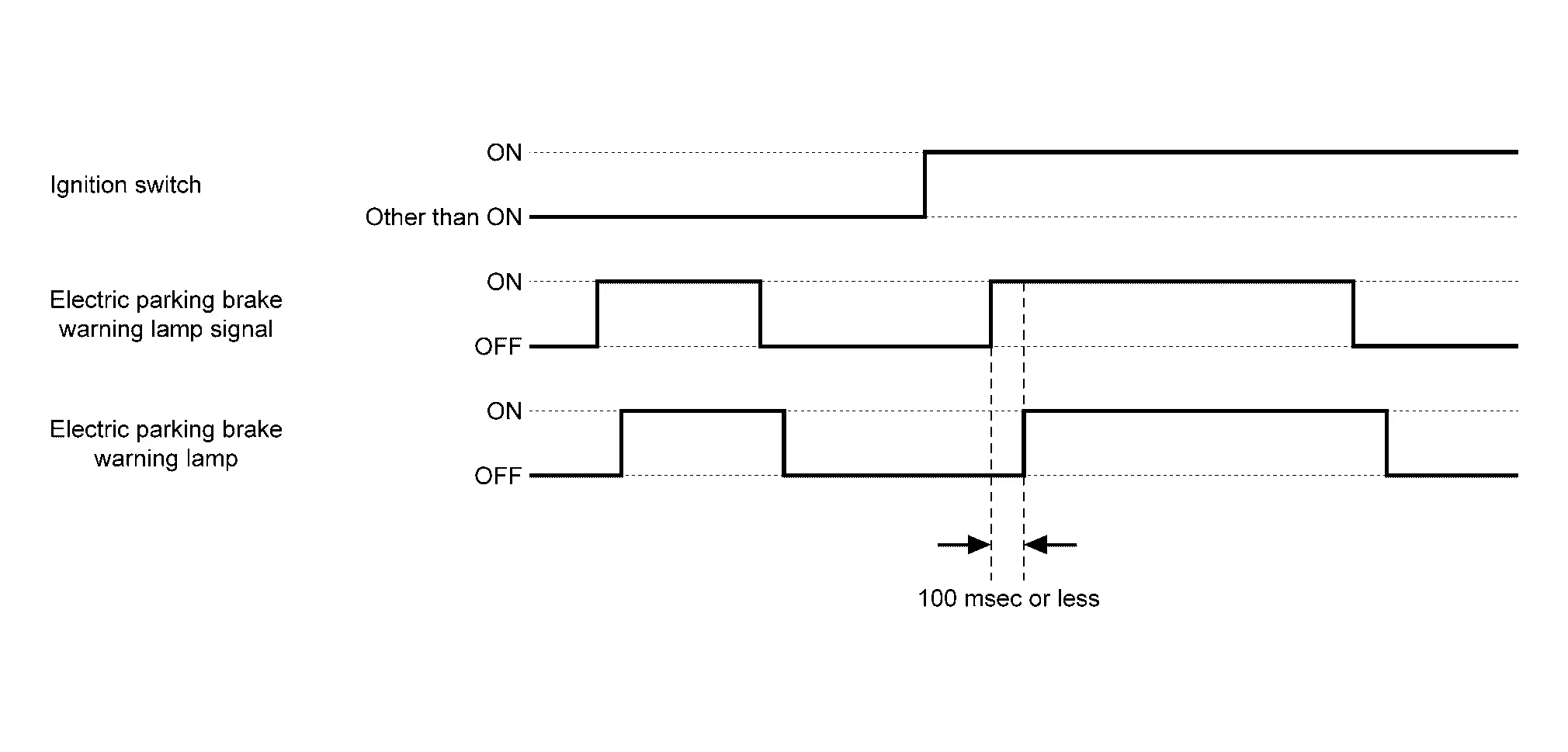
Electric Parking Brake Warning Lamp
DESIGN/PURPOSE
The electric parking brake Warning Lamp (Yellow) warns the driver of a malfunction in the electric parking brake system.

BULB CHECK
Applicable
SYNCHRONIZATION WITH MASTER WARNING LAMP
Applicable
OPERATION AT COMBINATION METER CAN COMMUNICATION CUT-OFF OR UNUSUAL SIGNAL
For actions on CAN communications blackout in the combination meter. Refer to Fail-Safe.
SYSTEM DIAGRAM
*: For DTCs that the electric parking brake Warning Lamp (Yellow) turns ON. Refer to DTC Index.
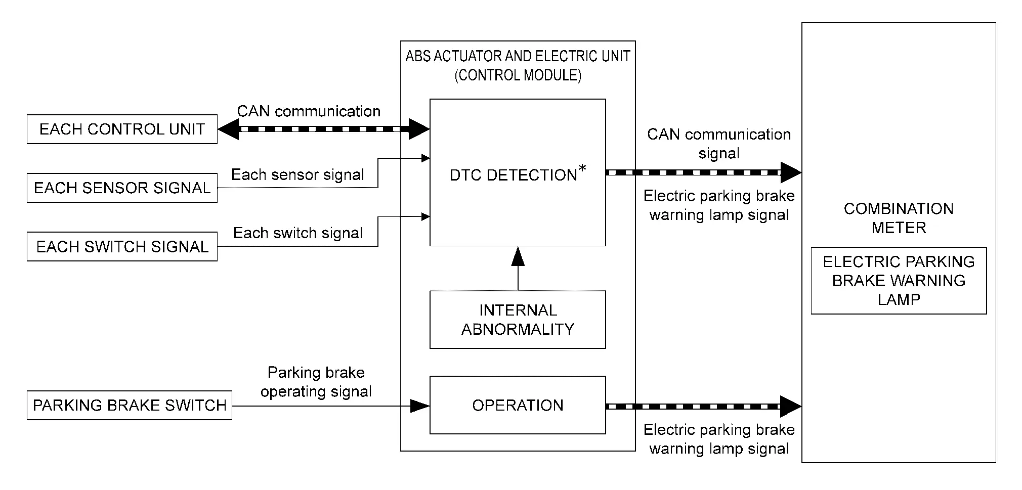
SIGNAL PATH
-
The ABS actuator and electric unit (control unit) transmits a electric parking brake warning lamp signal to the combination meter via CAN communication.
-
The combination meter turns ON the electric parking brake warning lamp (Yellow) when receiving a electric parking brake warning lamp signal.
-
For the relationship between warning lamp and DTC. Refer to DTC Index.
LIGHTING CONDITION
-
When combination meter is not receiving signal from ABS actuator and electric unit (control unit) via CAN communication.
-
When a malfunction is detected in parking brake switch.
-
When a malfunction is detected in other control unit (malfunction of CAN communication or malfunction of signal).
-
When a not operate the electric parking brake system (impossible of malfunction confirmation).
-
When a malfunction is detected in electric parking brake system.
-
For the relationship between warning lamp and DTC. Refer to DTC Index.
SHUTOFF CONDITION
-
When the condition listed below is satisfied.
-
Erase DTC
-
Other control unit is normal
-
-
Vehicle condition is sleep status.
TIMING CHART
Electric Shift Warning Lamp
KR15DDT
DESIGN/PURPOSE
The electric shift warning lamp illuminates when:
-
electric shift system is not normal. (Case 1)
-
driver door is not normal. (Case 2)

BULB CHECK
For 2 seconds after placing the ignition switch ON.
SYNCHRONIZATION WITH MASTER WARNING LAMP
Not applicable
OPERATION AT COMBINATION METER CAN COMMUNICATION CUT-OFF OR UNUSUAL SIGNAL
For actions on CAN communications blackout in the combination meter, refer to Fail-Safe.
SYSTEM DIAGRAM
Case 1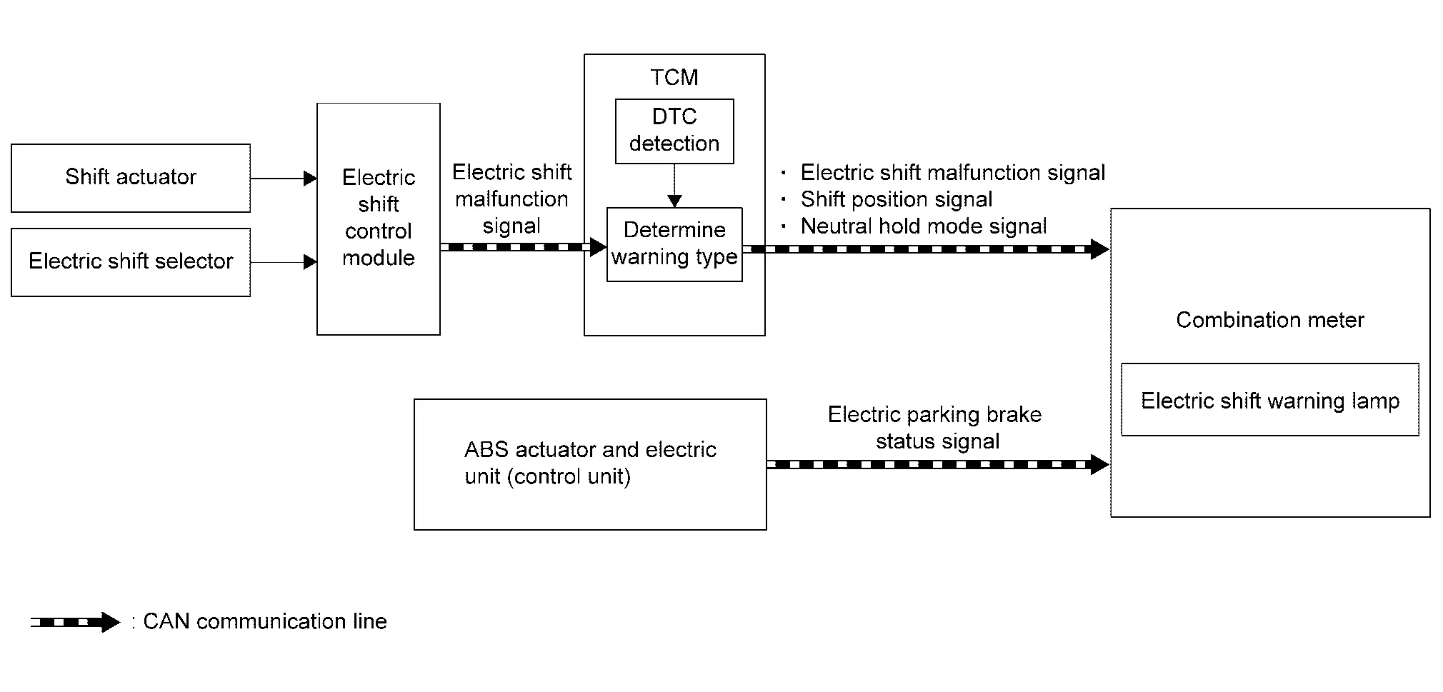
Case 2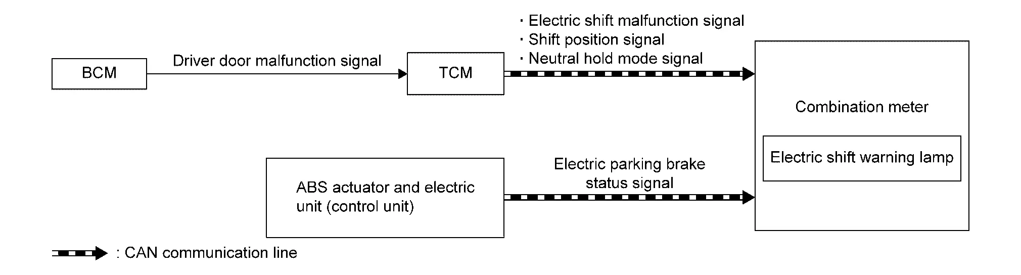
SIGNAL PATH
Case 1
-
Electric shift control module transmits an electric shift malfunction signal to the TCM when detecting malfunction in the electric shift system.
-
The TCM detects DTC when TCM receives an electric shift malfunction signal.
-
The TCM transmits an electric shift malfunction signal, a shift position signal, and a neutral hold mode signal to the combination meter when detecting DTC in TCM.
-
ABS actuator and electric unit (control unit) transmits an electric parking brake status signal to the combination meter.
-
The combination meter turns ON the electric shift warning lamp according to each signal. Refer to LIGHTING CONDITION.
Case 2
-
BCM transmits a driver door malfunction signal to the TCM when detecting a malfunction of driver door switch.
-
The TCM transmits an electric shift malfunction signal, a shift position signal, and a neutral hold mode signal to the combination meter when the TCM receives a malfunction signal from the BCM.
-
The ABS actuator and electric unit (control unit) transmits an electric parking brake status signal to the combination meter.
-
The combination meter turns ON the electric shift warning lamp according to each signal. Refer to LIGHTING CONDITION.
LIGHTING CONDITION
When all of the following conditions are satisfied. (Case 1 )
-
Electric shift system malfunction (Transmission does not shift to P position due to electric shift system malfunction)
-
Except neutral hold mode
-
Shift position is except P position
-
Nissan Ariya Vehicle speed is less than the specified vehicle speed
-
Parking brake is not applied
When all of the following conditions are satisfied. (Case 2)
-
Driver door malfunction signal is detected.
-
Except neutral hold mode
-
Shift position is except P position
-
Nissan Ariya Vehicle speed is less than the specified vehicle speed
-
Parking brake is not applied
SHUTOFF CONDITION
When any of the conditions listed below is satisfied. (Case 1)
-
In neutral hold mode
-
Shift position is P position
-
Electric shift system is normal
-
Nissan Ariya Vehicle speed is the specified vehicle speed or more
-
Parking brake is applied
When any of the conditions listed below is satisfied. (Case 2)
-
In neutral hold mode
-
Shift position is P position
-
Driver door malfunction signal is not detected
-
Nissan Ariya Vehicle speed is the specified vehicle speed or more
-
Parking brake is applied
Engine Oil Pressure Warning Lamp
DESIGN/PURPOSE
When engine oil pressure is low, the oil pressure warning lamp informs the driver of low oil pressure to prevent damage to the engine.

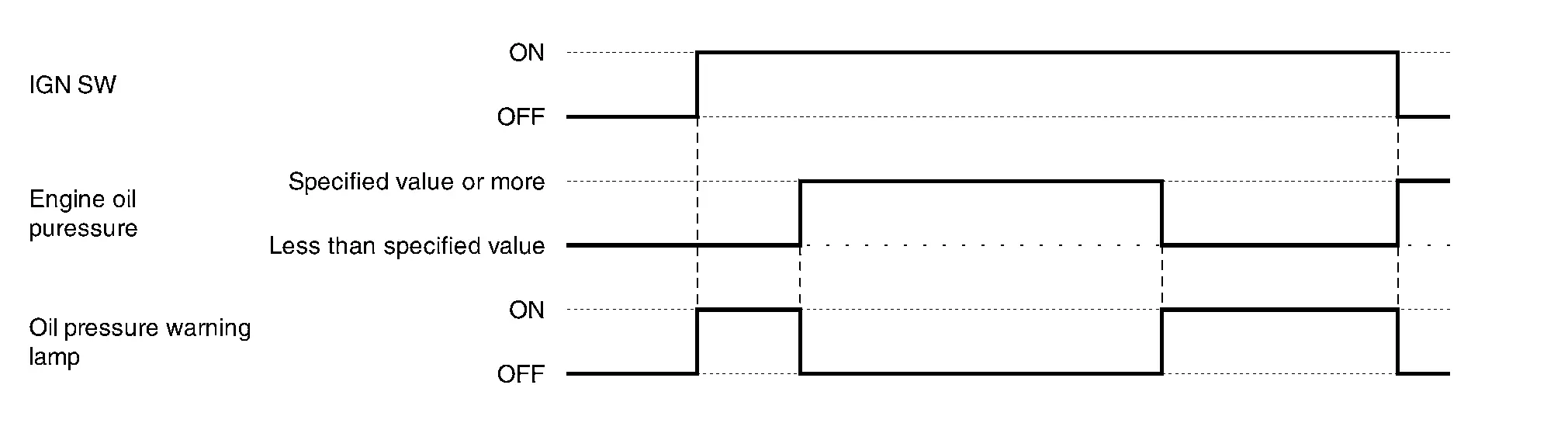
BULB CHECK
The bulb turns ON after placing the ignition switch ON and turns OFF after restarting the engine.
OPERATION AT COMBINATION METER CAN COMMUNICATION CUT-OFF OR UNUSUAL SIGNAL
For the operation for CAN communications blackout or abnormal signal reception, refer to Fail-Safe.
SYSTEM DIAGRAM
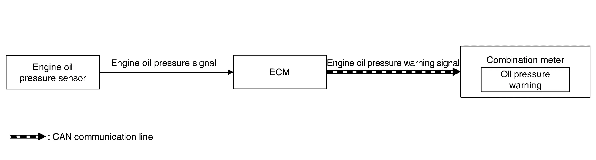
SIGNAL PATH
-
ECM reads the resistance value of an engine oil pressure sensor and transmits the engine oil pressure warning signal to combination meter via CAN communication.
-
The information display (on combination meter) is SHOWN/HIDDEN the engine oil pressure warning, according to the engine oil pressure sensor signal received from ECM.
LIGHTING CONDITION
When all of the following conditions is satisfied:
-
Ignition switch: ON
-
Engine running
-
Engine oil pressure is less than specified value.
SHUTOFF CONDITION
-
Ignition switch: OFF
-
Engine stop
-
Engine oil pressure is the specified value or more.
TIMING CHART
Front Fog Lamp Indicator Lamp
DESIGN/PURPOSE
Front fog lamp indicator lamp informs the driver that front fog lamp is in ON status.

BULB CHECK
Not applicable
SYNCHRONIZATION WITH MASTER WARNING LAMP
Not applicable
OPERATION AT COMBINATION METER CAN COMMUNICATION CUT-OFF OR UNUSUAL SIGNAL
For actions on CAN communications blackout in the combination meter. Refer to Fail-Safe.
SYSTEM DIAGRAM

SIGNAL PATH
-
BCM transmits front fog light status signal to combination meter via CAN communication.
-
When combination meter receives front fog light status signal, combination meter turns front fog lamp indicator lamp ON.
LIGHTING CONDITION
When front fog lamp is turned ON.
SHUTOFF CONDITION
When front fog lamp is turned OFF.
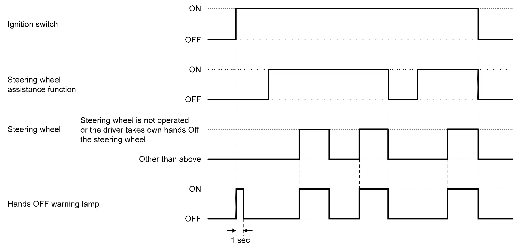
Hands OFF Warning Lamp
DESIGN/PURPOSE
The hands OFF warning lamp warns the driver that the steering wheel is not operated or the driver takes own hands Off the steering wheel for a period of time.

BULB CHECK
Hands OFF warning lamp turns ON after placing the ignition switch ON.
SYNCHRONIZATION WITH MASTER WARNING LAMP
Not applicable
OPERATION AT COMBINATION METER CAN COMMUNICATION CUT-OFF OR UNUSUAL SIGNAL
For actions on CAN communications blackout in the combination meter, refer to Fail-Safe.
SYSTEM DIAGRAM
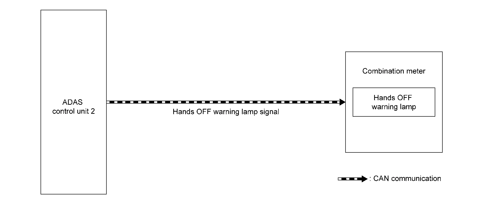
SIGNAL PATH
-
During steering support control, based on the steering torque signal received via CAN communication from the power steering control module, the ADAS control unit 2 detects operation of the steering wheel by the driver.
-
The ADAS control unit 2 transmits an hands OFF warning lamp signal to the combination meter via CAN communication when the steering wheel is not operated or the driver takes own hands Off the steering wheel for a period of time.
-
The combination meter turns ON the hands OFF warning lamp when receiving an hands OFF warning lamp signal.
LIGHTING CONDITION
The warning lamp turns ON when the steering wheel is not operated or the driver takes own hands Off the steering wheel for a period of time.
SHUTOFF CONDITION
The warning lamp turns OFF when the driver holds and operates the steering wheel again.
TIMING CHART
High Beam Assist Indicator Lamp
DESIGN/PURPOSE
High beam assist indicator lamp informs the driver that the high beam assist system is in operating status.
BULB CHECK
Not applicable
SYNCHRONIZATION WITH MASTER WARNING LAMP
Not applicable
OPERATION AT COMBINATION METER CAN COMMUNICATION CUT-OFF OR UNUSUAL SIGNAL
For actions on CAN communications blackout in the combination meter. Refer to Fail-Safe.
SYSTEM DIAGRAM
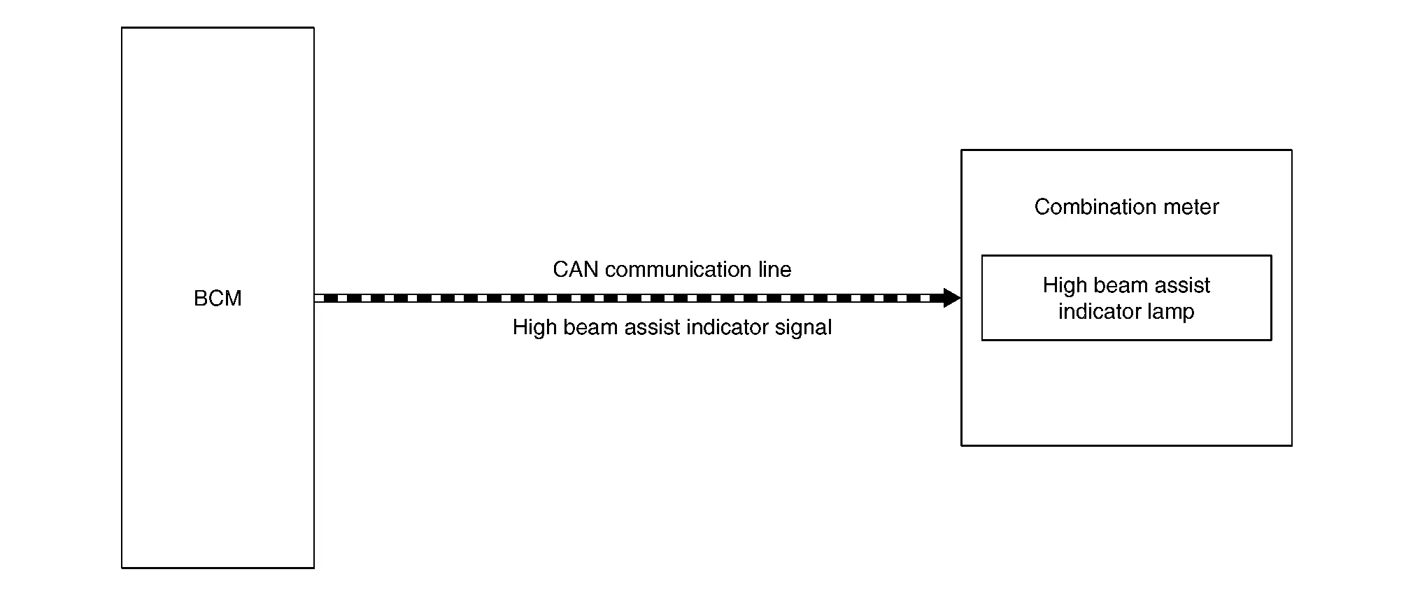
SIGNAL PATH
-
BCM transmits the high beam assist indicator signal to the combination meter via CAN communication when the high beam assist system operation permission conditions are satisfied.
-
When combination meter receives high beam assist indicator signal, combination meter turns high beam assist indicator lamp ON.
LIGHTING CONDITION
High beam assist system operation permission conditions are satisfied. (when all of following conditions are satisfied)
-
Ignition switch ON
-
Lighting switch AUTO (Only when the illuminating judgement by auto light function is ON. Refer to System Description.) (Except for Canada)
-
Lighting switch AUTO or 1ST (Only when the illuminating judgement by auto light function is ON. Refer to System Description.) (For Canada)
-
High beam assist switch ON
SHUTOFF CONDITION
High beam assist system operation permission conditions are not satisfied.
High Beam Indicator Lamp
DESIGN/PURPOSE
High beam indicator lamp informs the driver that headlamp (HI) is in ON status.

BULB CHECK
Not applicable
SYNCHRONIZATION WITH MASTER WARNING LAMP
Not applicable
OPERATION AT COMBINATION METER CAN COMMUNICATION CUT-OFF OR UNUSUAL SIGNAL
For actions on CAN communications blackout in the combination meter. Refer to Fail-Safe.
SYSTEM DIAGRAM
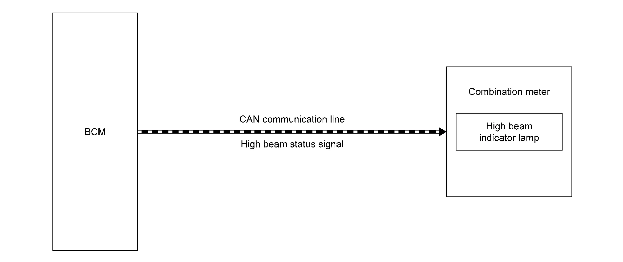
SIGNAL PATH
-
BCM transmits high beam status signal to combination meter via CAN communication.
-
When combination meter receives high beam status signal, combination meter turns high beam indicator lamp ON.
LIGHTING CONDITION
When headlamp (HI) is turned ON.
SHUTOFF CONDITION
When headlamp (HI) is turned OFF.
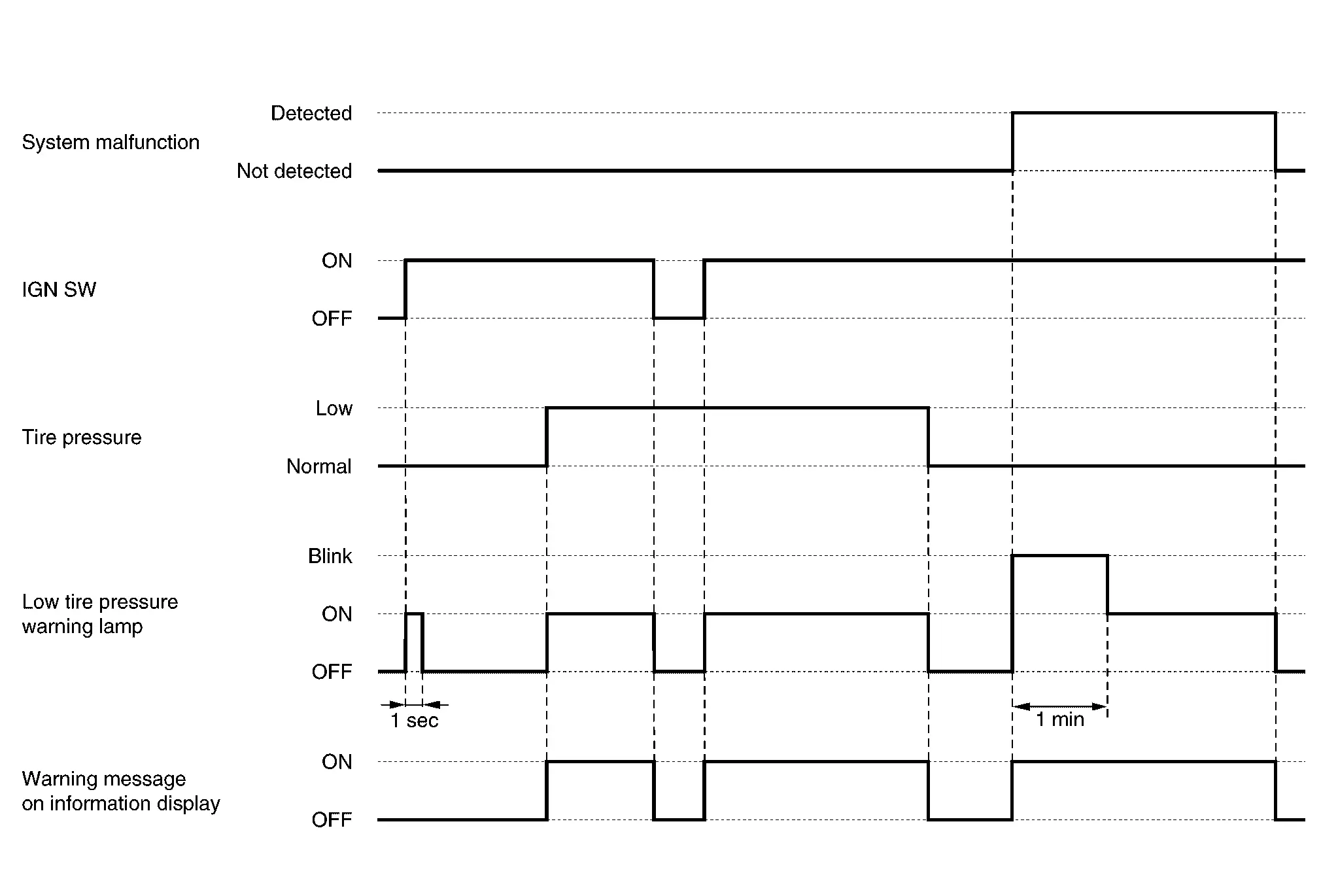
Low Tire Pressure Warning Lamp
DESIGN/PURPOSE
-
When tire pressure is low, TPMS (Tire Pressure Monitoring System) turns low tire pressure warning lamp ON to warn the driver.

-
When the TPMS detects the system malfunction, the system blinks (1 minute) ŌćÆ turns ON low tire pressure warning lamp.
Details for TPMS (Tire Pressure Monitoring System), refer to System Description.
BULB CHECK
Turns ON for 1second, then turns OFF.
SYNCHRONIZATION WITH MASTER WARNING
Applicable
For master warning, refer to Master Warning Lamp.
OPERATION AT COMBINATION METER CAN COMMUNICATION CUT-OFF OR UNUSUAL SIGNAL
For the operation for CAN communication blackout in the combination meter, refer to Fail-Safe.
SYSTEM DIAGRAM
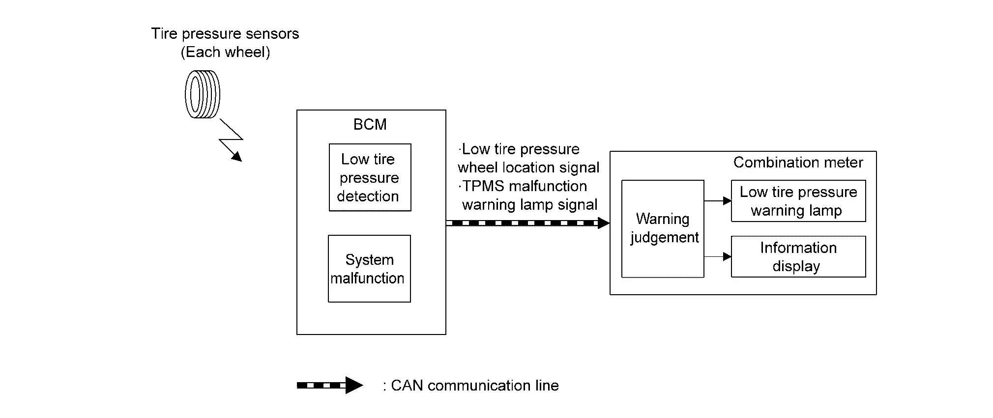
SIGNAL PATH
-
BCM receives a signal transmitted from the tire pressure sensors/transmitters installed in each wheel.
-
If BCM detects following condition, it sends the signal to the combination meter via CAN communication.
-
Tire pressure is low
-
System malfunction is detected
-
-
Combination meter turns the low tire pressure warning lamp ON according to the signal. In addition, warning message will be displayed in the Nissan Ariya vehicle information display.
LIGHTING CONDITION
When any of the following conditions is satisfied:
-
Tire pressure is low.
-
System malfunction is detected.
-
CAN communication line malfunction is detected.
For DTC, refer to DTC Index.
SHUTOFF CONDITION
When any of the following conditions is satisfied:
-
Ignition switch is not in ON position.
-
All tire pressures are normal.
-
System malfunction is not detected.
TIMING CHART
Malfunction Indicator Lamp (MIL)
DESIGN/PURPOSE
When a malfunction which increases exhaust gases is detected, ECM turns ON MIL and informs the driver of the necessity of inspection and repair.
When a malfunction which causes damage to the catalyst is detected, ECM immediately blinks MIL to alert the driver.
BULB CHECK
The bulb turns ON after placing the ignition switch ON and turns OFF after restarting the engine.
OPERATION AT COMBINATION METER CAN COMMUNICATION CUT-OFF OR UNUSUAL SIGNAL
For the operation for CAN communication blackout in the combination meter, refer to Fail-Safe.
SYSTEM DIAGRAM
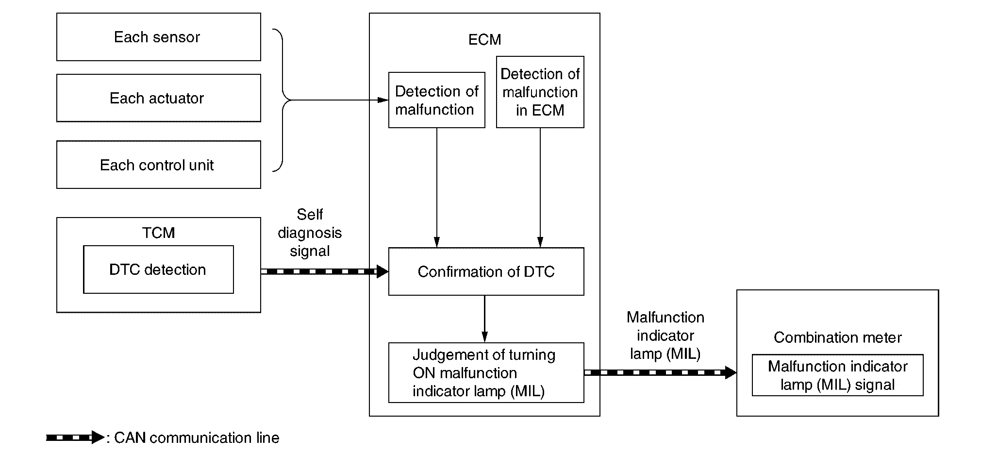
SIGNAL PATH
-
When the lighting conditions of the malfunction indicator lamp (MIL) are satisfied, ECM transmits a malfunction indicator lamp (MIL) signal to the combination meter via CAN communication.
-
The combination meter turns ON or blinks the malfunction indicator lamp (MIL), according to a signal received from ECM.
LIGHTING CONDITION
When all of the following conditions are satisfied:
-
Ignition switch: ON
-
DTC which influences on exhaust gasses is judged.
For DTCs that the malfunction indicator lamp turns ON and the number of DTC diagnosis trips, refer to DTC Index.
SHUTOFF CONDITION
When any of the following conditions is satisfied:
-
Ignition switch: OFF
-
Erase DTC
TIMING CHART
Master Warning Lamp
DESIGN/PURPOSE
The master warning lamp warns to driver when information display warning displayed.

SYSTEM DIAGRAM
DESCRIPTION
The master warning lamp (red) and master warning lamp (yellow) turn ON/OFF in coordination with warning on the information display.
X: Applicable
| Information display warning item | Master warning lamp | Reference | |
|---|---|---|---|
| Red | Yellow | ||
| Door open warning (While driving) | X | Refer to Door Open Warning. | |
| Door open warning (While driving) (Trunk) | X | ||
| Intelligent Key system malfunction | X | Refer to Intelligent Key System Malfunction. | |
| Take away warning | X | Refer to Take Away Warning (Information Display). | |
| Shift P warning | X | Refer to Shift P Warning. | |
| Headlamp warning | X | Refer to Headlamp Warning. | |
| Engine warning | X | Refer to Indicator/Information. | |
| CVT system warning | X | Refer to CVT System Warning. | |
| Oil Level warning | X | Refer to Oil Level Warning. | |
| AWD warning | X | Refer to AWD Warning. | |
| Electric shift warning | X | X | Refer to Electric Shift Warning. |
| Low tire pressure warning | X | Refer to Low Tire Pressure Warning. | |
| Washer fluid warning | X | Refer to Washer fluid warning. | |
| Parking brake warning | X | Refer to Parking Brake Warning. | |
| Automatic brake hold warning | X | Refer to Automatic Brake Hold Warning. | |
| Chassis control warning | X | Refer to Chassis control warning. | |
| Parking sensor error | X | Refer to System Description. | |
Position Lamp Indicator Lamp
DESIGN/PURPOSE
Position lamp indicator lamp informs the driver that parking lamp, license plate lamp, side marker lamp and tail lamp are in ON status.

BULB CHECK
Not applicable
SYNCHRONIZATION WITH MASTER WARNING LAMP
Not applicable
OPERATION AT COMBINATION METER CAN COMMUNICATION CUT-OFF OR UNUSUAL SIGNAL
For actions on CAN communications blackout in the combination meter. Refer to Fail-Safe.
SYSTEM DIAGRAM
SIGNAL PATH
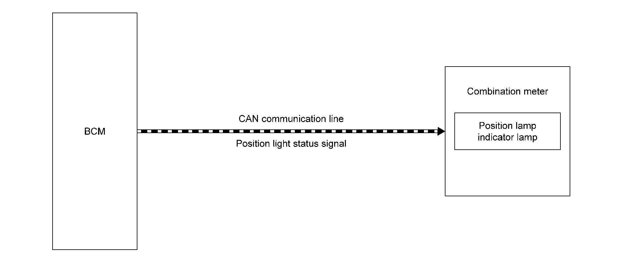
-
BCM transmits position light status signal to combination meter via CAN communication.
-
When combination meter receives position light status signal, combination meter turns position lamp indicator lamp ON.
LIGHTING CONDITION
When parking, license plate, side marker and tail lamp are turned ON.
NOTE:
When headlamp is turned ON while parking, license plate, side marker and tail lamp are ON the position lamp indicator lamp is turns OFF.
SHUTOFF CONDITION
When parking, license plate, side marker and tail lamp are turned OFF.
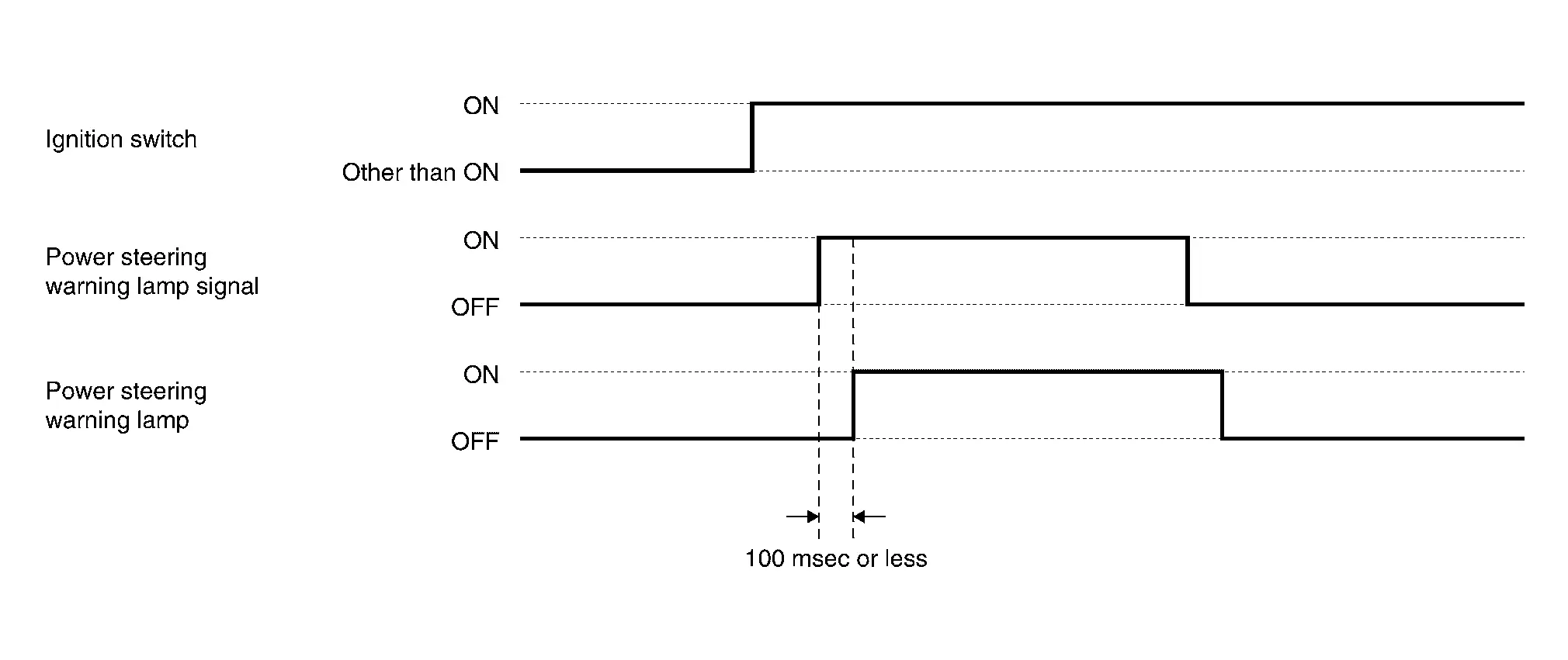
Power Steering Warning Lamp
DESIGN/PURPOSE
It indicates that fail-safe mode is engaged and enters a manual steering state (Control turning force steering wheel becomes heavy).

BULB CHECK
Also turns ON when ignition switch ON, for purpose of lamp check. Turns OFF after the engine starts, if system is normal.
SYNCHRONIZATION WITH MASTER WARNING LAMP
Not applicable
OPERATION AT COMBINATION METER CAN COMMUNICATION CUT-OFF OR UNUSUAL SIGNAL
For actions on CAN communications blackout in the combination meter, refer to Fail-Safe.
SYSTEM DIAGRAM
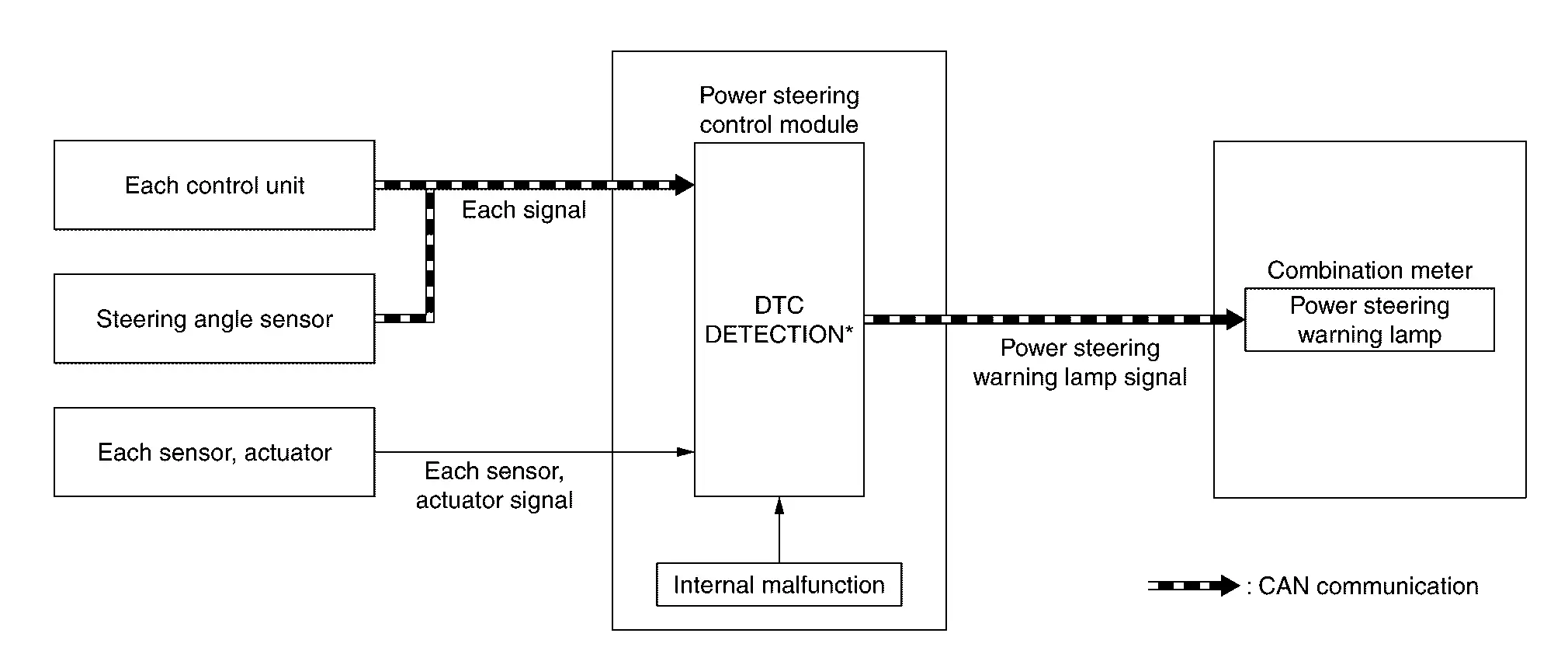
*: For DTCs that the steering warning lamp turns ON, refer to DTC Index.
SIGNAL PATH
-
If any malfunction occurs in the system and the system enters into a manual steering state according to fail-safe function, power steering control module transmits power steering warning lamp signal to combination meter.
-
Combination meter turns ON the power steering warning lamp according to the power steering warning lamp signal.
LIGHTING CONDITION
-
Any malfunction occurs in the EPS and steering assist torque is not generated.
-
For the relationship between warning lamp and DTC, refer to DTC Index.
SHUTOFF CONDITION
-
The ignition switch is in a position OFF.
-
DTC is deleted.
TIMING CHART
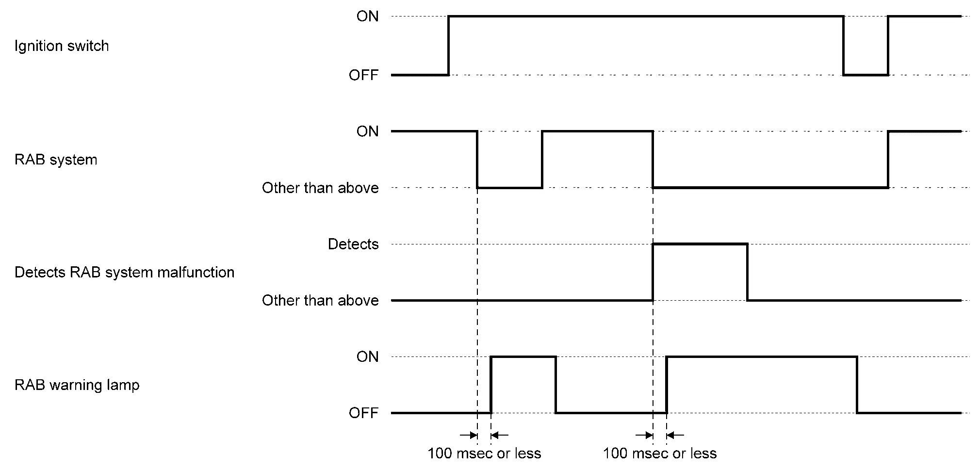
RAB Warning Lamp
DESIGN/PURPOSE
-
The RAB warning lamp warns the driver that RAB system is OFF.
-
The RAB warning lamp warns the driver of a malfunction in the RAB system.

BULB CHECK
RAB warning lamp turns ON after placing the ignition switch ON.
SYNCHRONIZATION WITH MASTER WARNING LAMP
Not applicable
OPERATION AT COMBINATION METER CAN COMMUNICATION CUT-OFF OR UNUSUAL SIGNAL
For actions on CAN communications blackout in the combination meter, refer to Fail-Safe.
SYSTEM DIAGRAM
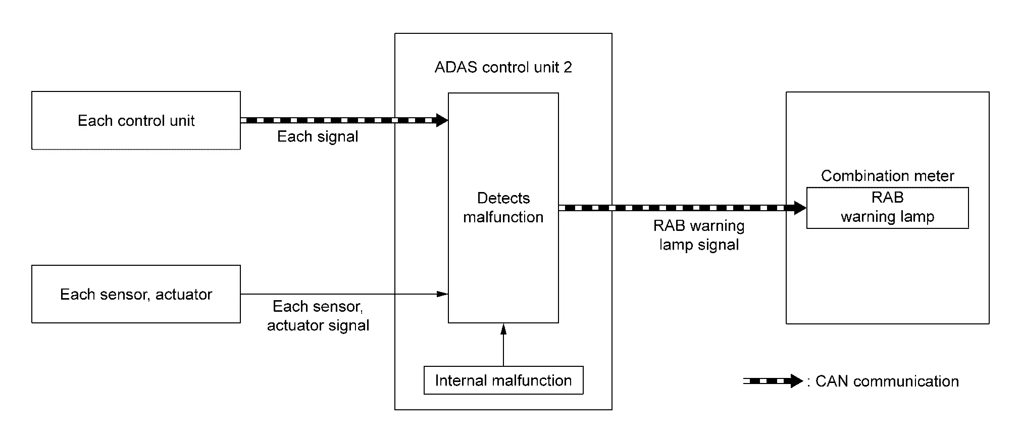
SIGNAL PATH
-
The ADAS control unit 2 receives a system selection signal from the combination meter via CAN communication when RAB system ON is not selected.
-
The ADAS control unit 2 transmits an RAB warning lamp signal to the combination meter via CAN communication when detecting a malfunction or RAB system ON is not selected.
-
The combination meter turns ON the RAB warning lamp when receiving an RAB warning lamp signal.
LIGHTING CONDITION
The warning lamp turns ON when:
-
RAB system OFF.
-
A malfunction is detected in the RAB system.
SHUTOFF CONDITION
The warning lamp turns OFF when:
-
RAB system ON.
-
DTC is deleted.
-
The ignition switch is in a position other than ON.
TIMING CHART
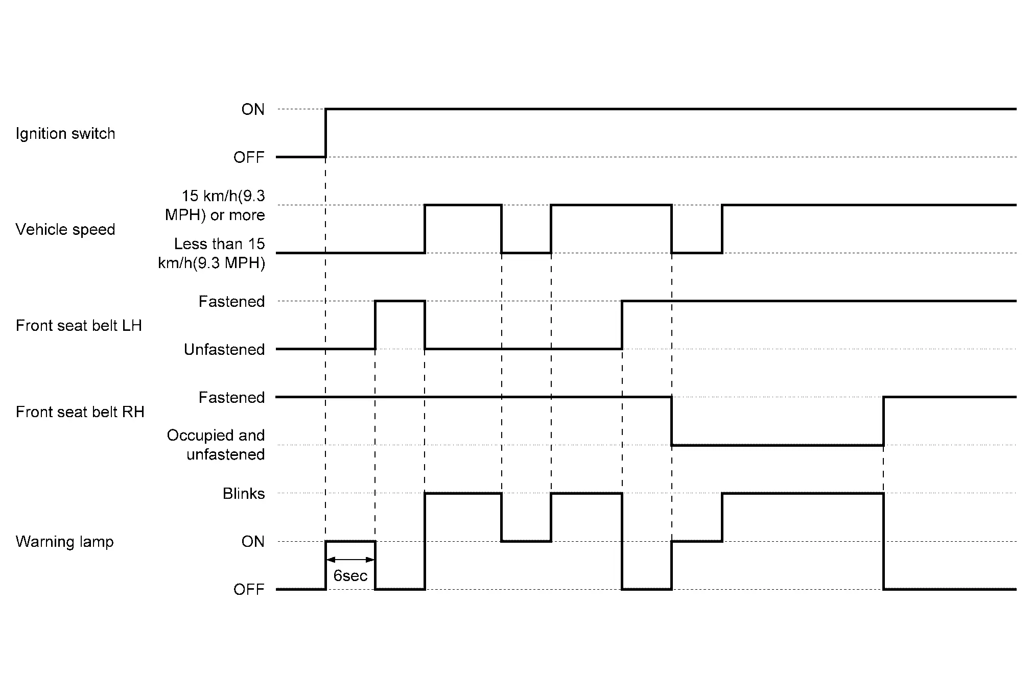
Seat Belt Warning Lamp
DESIGN/PURPOSE
Seat belt warning lamp warns the driver that front LH or front RH seat belt is unfastened.

BULB CHECK
Not applicable.
SYNCHRONIZATION WITH MASTER WARNING LAMP
Not applicable.
SYSTEM DIAGRAM
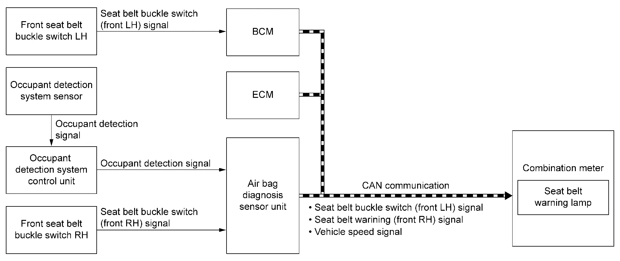
SIGNAL PATH
-
Combination meter turns seat belt warning lamp ON according to seat belt buckle switch (front LH) signal or seat belt warning (front RH) signal.
-
The seat belt warning (front RH) signal sent to combination meter when the air bag diagnosis sensor unit detects that a person sits in the front seat RH.
-
Subsequently, when a person does not sit in the front seat RH, the illumination control of the warning lamp of the front seat belt RH is not performed.
LIGHTING CONDITION
Combination meter turns seat belt warning lamp ON at 6 seconds when all of the following conditions are satisfied.
-
Ignition switch is ON.
-
When any of the conditions listed below are satisfied.
-
Front seat belt LH is unfastened.
-
Front seat belt RH is unfastened and person sit in the front seat RH.
-
BLINKS CONDITION
Combination meter turns seat belt warning lamp blinks when all of the following conditions are satisfied.
-
Ignition switch is ON.
-
Vehicle speed is 15 km/h (9.3 MPH) or more.
-
When any of the conditions listed below are satisfied.
-
Front seat belt LH is unfastened.
-
Front seat belt RH is unfastened and person sit in the front seat RH.
-
NOTE:
When blinking, it turn ON when all of the following conditions are satisfied.
-
Nissan Ariya Vehicle speed is less than 3 km/h (1.8 MPH).
-
Shift position is P or parking brake ON
SHUTOFF CONDITION
Combination meter turns seat belt warning lamp OFF when any of the following conditions are satisfied.
-
Ignition switch is OFF.
-
When all of the conditions listed below are satisfied while the ignition switch is ON
-
Front seat belt LH is fastened.
-
Front seat belt RH is fastened or person does not sit in the front seat RH.
-
TIMING CHART
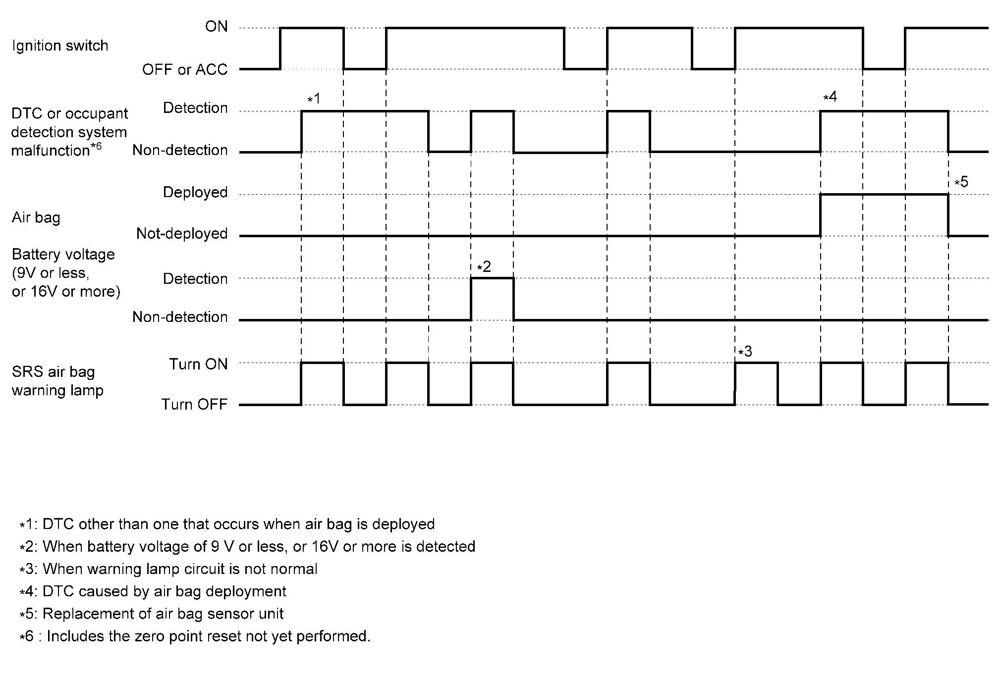
SRS Air Bag Warning Lamp
DESIGN/PURPOSE
The warning lamp warns the driver that SRS air bag system is not normal.

BULB CHECK
For 7 seconds after placing the ignition switch ON.
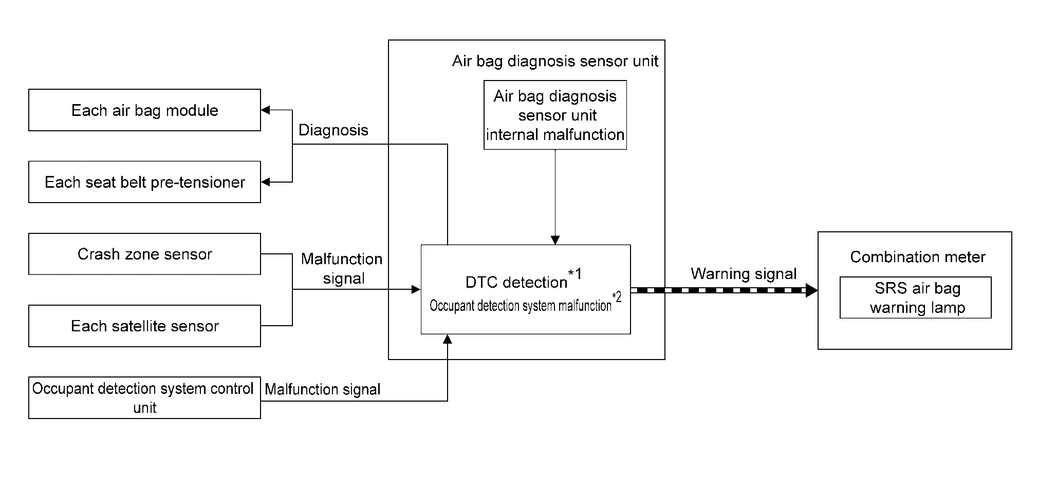
SYSTEM DIAGRAM
NOTE:
-
*1: For DTCs of the SRS air bag system, refer to DTCŌĆéIndex.
-
*2: For occupant detection system control unit, malfunction signal includes the zero point reset not yet performed.
SIGNAL PATH
-
When a malfunction is detected, air bag diagnosis sensor unit transmits the warning signal to combination meter.
-
Combination meter turns SRS air bag warning lamp ON, according to the received signal.
LIGHTING CONDITION
When a malfunction of the following part or status is detected.
-
Deployment of air bag
-
Air bag diagnosis sensor unit
-
Combination meter
-
Circuit between air bag diagnosis sensor unit and combination meter
-
Battery voltage not normal (approximately 9 V or less, or 16 V or more)
-
Each air bag module main unit
-
Each seat belt pre-tensioner main unit
-
Crash zone sensor main unit
-
Each satellite sensor
-
Circuit between each air bag module and air bag diagnosis sensor unit
-
Circuit between each seat belt pre-tensioner and air bag diagnosis sensor unit
-
Circuit between crash zone sensor and air bag diagnosis sensor unit
-
Circuit between each satellite sensor and air bag diagnosis sensor unit
-
Occupant detection system control unit (Includes the zero point reset not yet performed.)
NOTE:
For the relation between warning lamp and DTC, refer to DTCŌĆéIndex.
SHUTOFF CONDITION
When Being Turned ON Due to Deployment of Air Bag
Replace air bag diagnosis sensor unit.
When Turned ON Due to a Malfunction of SRS Air Bag Warning Lamp Circuit
Repair SRS air bag warning lamp circuit system.
When Turned ON Due to a Malfunction of Air Bag Module or Air Bag Module Circuit
Repair the malfunctioning part. Erase self-diagnosis result memory.
When Turned ON Due to a Malfunction of Occupant Detection System Control Unit
-
Perform the zero point reset.
-
Replace Occupant detection system control unit or the malfunction parts.
TIMING CHART
Turn Signal Indicator Lamp
DESIGN/PURPOSE
Turn signal indicator lamp informs the driver that turn signal lamp is in ON status.

BULB CHECK
Not applicable
SYNCHRONIZATION WITH WARNING CHIME
Synchronization is applied.
For warning chime. Refer to System Description.
SYNCHRONIZATION WITH MASTER WARNING LAMP
Not applicable
OPERATION AT COMBINATION METER CAN COMMUNICATION CUT-OFF OR UNUSUAL SIGNAL
For actions on CAN communications blackout in the combination meter. Refer to Fail-Safe.
SYSTEM DIAGRAM

SIGNAL PATH
-
BCM transmits turn indicator signal to combination meter via CAN communication.
-
Combination meter blinks the turn signal indicator lamp according to the turn indicator signal.
LIGHTING CONDITION
Turn signal indicator lamp (LH)
-
When turn signal lamp (LH) is turned ON.
Turn signal indicator lamp (RH)
-
When turn signal lamp (RH) is turned ON.
SHUTOFF CONDITION
Turn signal indicator lamp (LH)
-
When turn signal lamp (LH) is turned OFF.
Turn signal indicator lamp (RH)
-
When turn signal lamp (RH) is turned OFF.
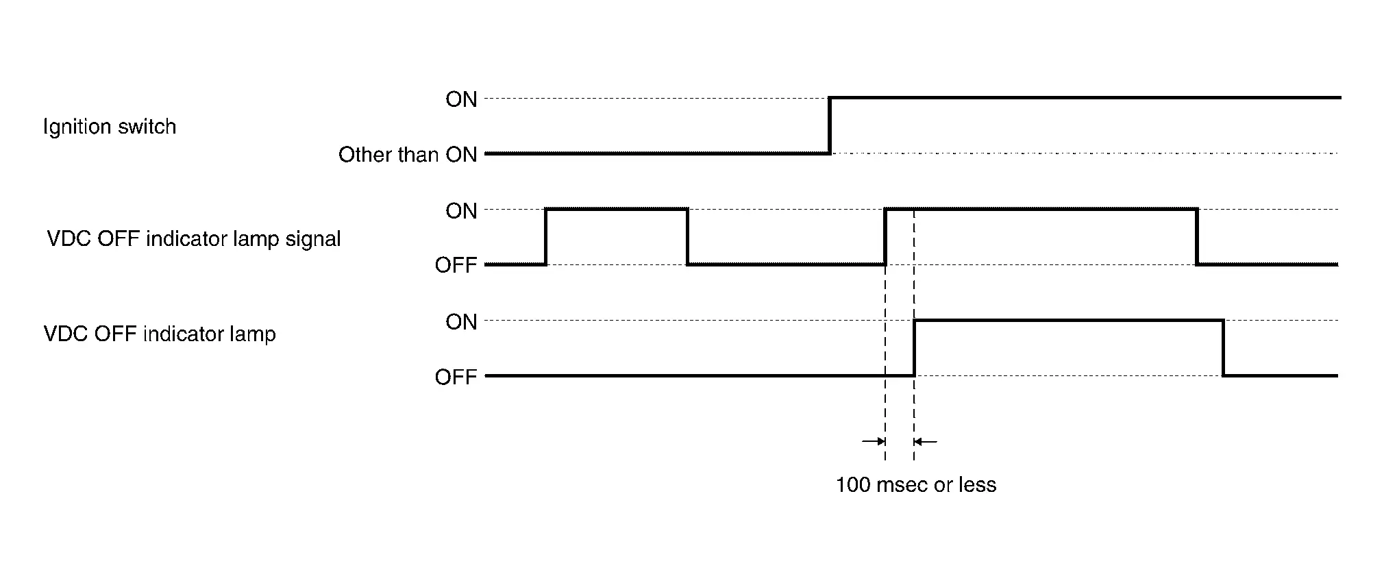
VDC OFF Indicator Lamp
DESIGN/PURPOSE
The VDC OFF indicator lamp warns the driver that VDC function and TCS function are OFF.
BULB CHECK
The VDC OFF indicator lamp turns ON and stays ON for 1 second after ON the ignition switch.
SYNCHRONIZATION WITH MASTER WARNING LAMP
Not applicable
OPERATION AT COMBINATION METER CAN COMMUNICATION CUT-OFF OR UNUSUAL SIGNAL
For actions on CAN communications blackout in the combination meter. Refer to Fail-Safe.
SYSTEM DIAGRAM
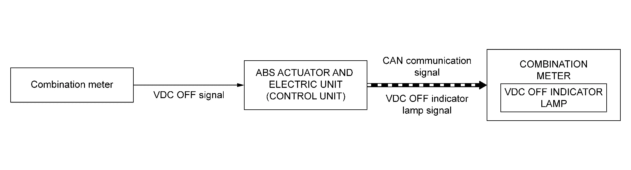
SIGNAL PATH
-
The ABS actuator and electric unit (control unit) receives a VDC OFF signal from the integral switch.
-
The ABS actuator and electric unit (control unit) transmits a VDC OFF indicator lamp signal to the combination meter via CAN communication according to the received VDC OFF signal.
-
The combination meter turns ON the VDC OFF indicator lamp when receiving a VDC OFF indicator lamp signal.
LIGHTING CONDITION
When all of the following conditions are satisfied:
-
Ignition switch ON
-
VDC OFF setting ON (VDC function and TCS function non-operational status)
SHUTOFF CONDITION
When the condition listed below is satisfied while the ignition switch ON:
-
Ignition switch other than ON
-
VDC OFF setting OFF (VDC function and TCS function standby status)
-
-
Ignition switch OFF
TIMING CHART
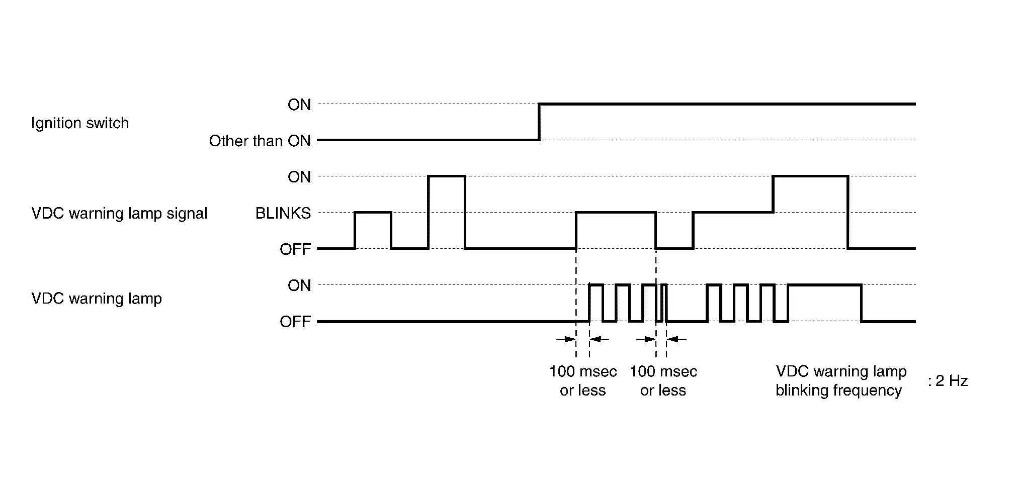
VDC Warning Lamp
DESIGN/PURPOSE
-
When VDC function, TCS function, or brake limited slip differential (BLSD) function is activated, the VDC warning lamp blinks to inform the driver of the activation of the function.
-
When VDC function, TCS function, ABS function, EBD function, brake limited slip differential (BLSD) function, brake assist function, brake force distribution function or hill start assist function of the ABS actuator and electric unit (control unit) has a malfunction, the VDC warning lamp turns ON to warn the driver of the malfunction.
NOTE:
The VDC warning lamp may turn ON when the brake warning lamp or ABS warning lamp turns ON. For details, refer to System Description.
BULB CHECK
The VDC warning lamp turns ON and stays ON for 1 second after ON the ignition switch.
SYNCHRONIZATION WITH MASTER WARNING LAMP
Not applicable
OPERATION AT COMBINATION METER CAN COMMUNICATION CUT-OFF OR UNUSUAL SIGNAL
For actions on CAN communications blackout in the combination meter. Refer to Fail-Safe.
SYSTEM DIAGRAM
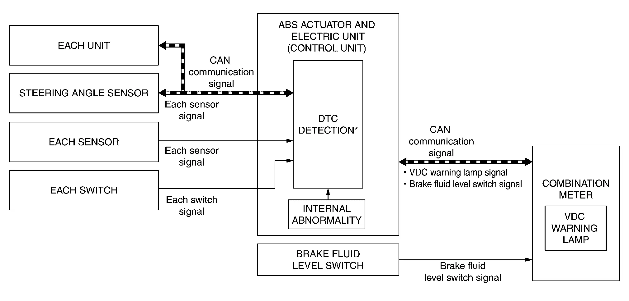
*: For DTCs that the VDC warning lamp turns ON. Refer to DTC Index.
SIGNAL PATH
When Operating VDC Function, TCS Function, Brake Limited Slip Differential (BLSD) Function
-
The ABS actuator and electric unit (control unit) transmits a VDC warning lamp signal to the combination meter via CAN communication when operating in the VDC function, TCS function, or brake limited slip differential (BLSD) function.
-
The combination meter blinks the VDC warning lamp when receiving a VDC warning lamp signal.
When VDC Function, TCS Function, ABS Function, EBD Function, Brake Limited Slip Differential (BLSD) Function, Brake Assist Function, Brake Force Distribution Function, hill start assist Function, Are In Abnormal State
-
The ABS actuator and electric unit (control unit) transmits a VDC warning lamp signal to the combination meter via CAN communication when detecting a malfunction in the VDC function, TCS function, brake limited slip differential (BLSD) function, brake assist function, brake force distribution function or hill start assist function.
-
The combination meter turns ON the VDC warning lamp when receiving a VDC warning lamp signal.
-
For the relationship between warning lamp and DTC. Refer to DTC Index.
LIGHTING CONDITION
-
A malfunction is detected in the VDC function, TCS function, ABS function, EBD function, brake limited slip differential (BLSD) function, brake assist function, brake force distribution function or hill start assist function of the ABS actuator and electric unit (control unit).
-
For the relationship between warning lamp and DTC. Refer to DTC Index.
BLINKING CONDITION
When VDC function, TCS function, or brake limited slip differential (BLSD) function is under operating conditions.
SHUTOFF CONDITION
-
When the condition listed below is satisfied while the ignition switch ON:
-
Erase DTC
-
-
When VDC function, TCS function, or brake limited slip differential (BLSD) function is not under operating conditions.
-
The ignition switch is in a position other than ON.
TIMING CHART
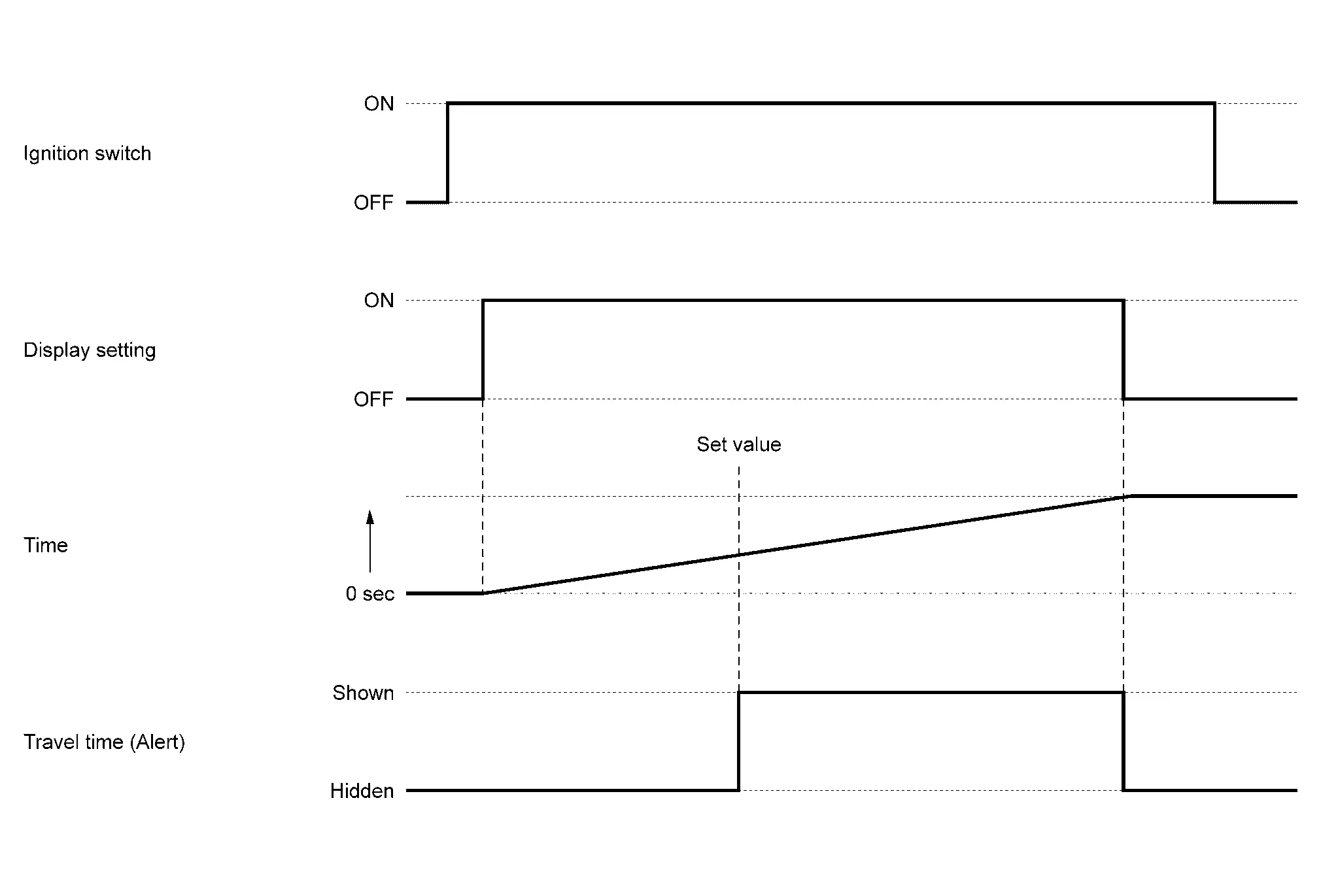
Warning/indicator (on Information Display)
Alert
DESIGN/PURPOSE
Travel Time
To warn the driver when driving the vehicle more than set value time.
| Symbol | Massage |
|---|---|
|
|
Time for a break? |

SYNCHRONIZATION WITH MASTER WARNING LAMP
Not applicable
SYSTEM DIAGRAM
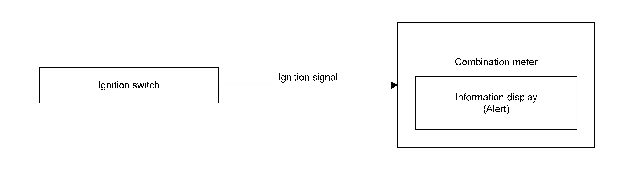
SIGNAL PATH
Combination meter will operate the timer after placing the ignition switch ON.
WARNING/INDICATOR OPERATING CONDITION
When all of the following conditions are satisfied:
-
Ignition switch ON
-
When time exceeds a set value
WARNING/INDICATOR CANCEL CONDITION
-
Ignition switch OFF
-
Press the OK, LEFT/BACK, or RIGHT switch
TIMING CHART
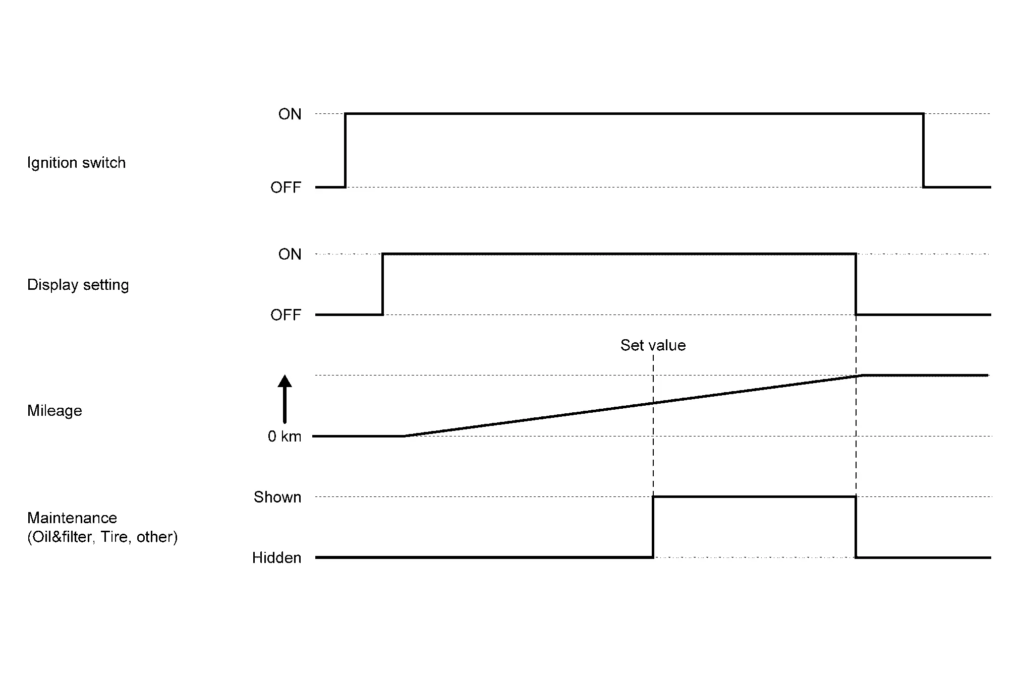
Maintenance
DESIGN/PURPOSE
The combination meter alerts the driver maintenance items (engine oil, oil filter, tires or other) when mileage exceeds a set value.
| Symbol | Message |
|---|---|
|
|
Oil and Filter |
|
|
Tire |
|
|
Other |


SYNCHRONIZATION WITH MASTER WARNING LAMP
Not applicable
SYSTEM DIAGRAM
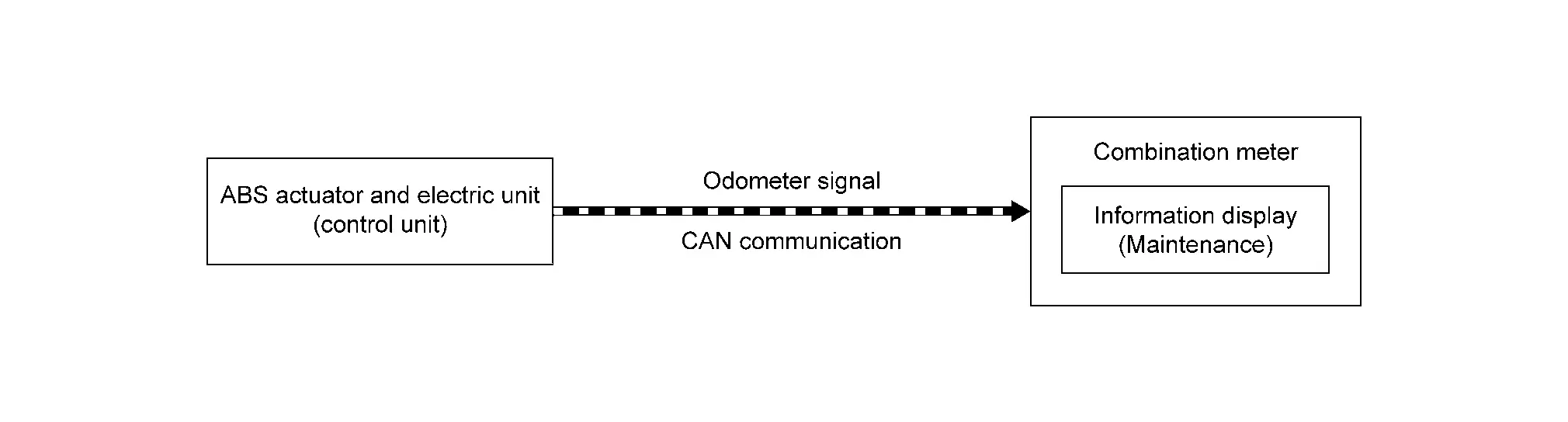
SIGNAL PATH
Combination meter will show the maintenance items according to odometer signal via CAN communication.
WARNING/INDICATOR OPERATING CONDITION
When all of the following conditions are satisfied:
-
Ignition switch ON
-
When mileage exceeds a set value
WARNING/INDICATOR CANCEL CONDITION
Press the OK, BACK/LEFT or RIGHT switch
TIMING CHART
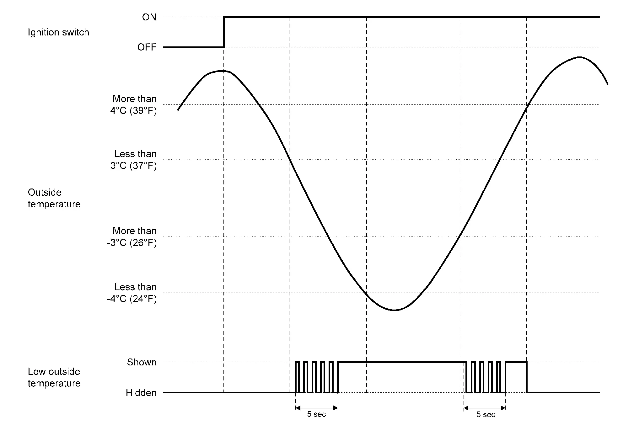
Low outside temperature display
DESIGN/PURPOSE
To warn the driver that the outside air temperature is low.

SYNCHRONIZATION WITH MASTER WARNING LAMP
Not applicable
SYSTEM DIAGRAM

SIGNAL PATH
Combination meter will show the display low outside temperature according to ambient sensor signal from ambient sensor.
For ambient temperature display, refer to System Description.
WARNING/INDICATOR OPERATING AND CANCEL CONDITION
| Outside temperature display | Status |
|---|---|
| Less than 3┬░C (37┬░F) | Blink (5 sec) ŌåÆ On |
| Less than -4┬░C (24┬░F) | On |
| More than -3┬░C (26┬░F) | Blink (5 sec) ŌåÆ On |
| More than 4┬░C (39┬░F) | Off |
TIMING CHART
Oil Level Warning
DESIGN/PURPOSE
The oil level indicator judges and displays engine oil level. When engine oil level is insufficient, the oil level indicator shows an engine oil level low warning to the driver. When oil level sensor is in abnormal conditions, an oil level sensor warning is displayed.
| Symbol | Message |
|---|---|
|
|
Low Oil Level |
| Symbol | Message |
|---|---|
|
|
Sensor Fault See OwnerŌĆÖs Manual |
SYNCHRONIZATION WITH MASTER WARNING LAMP
Refer to Master Warning Lamp.
SYSTEM DIAGRAM
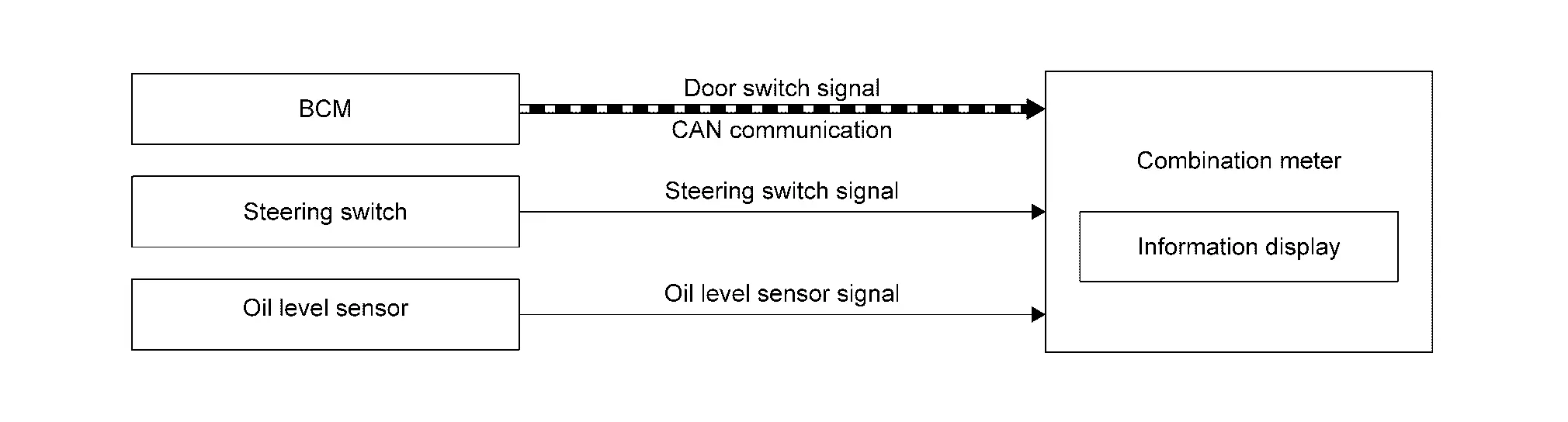
SIGNAL PATH
-
BCM transmits a door switch signal to the combination meter via CAN communication.
-
Oil level sensor transmits an oil level sensor signal to the combination meter.
-
Combination meter displays engine oil level to the information display.
-
Check engine oil level when the following condition is satisfied:
-
A lapse of approximately 5 minutes after placing the ignition switch ON.
-
Door switch (driver side): ON (Driver's door is open)
-
WARNING/INDICATOR OPERATING CONDITION
Oil level low warning and oil level sensor warning are displayed under the following conditions:
Oil Level Low Warning
-
Ignition switch: ON
-
When engine oil level is low (After engine oil level check)
Oil Level Sensor Warning
-
Ignition switch: ON
-
Oil level sensor abnormality
Meter Illumination Control
System Description
SYSTEM DIAGRAM
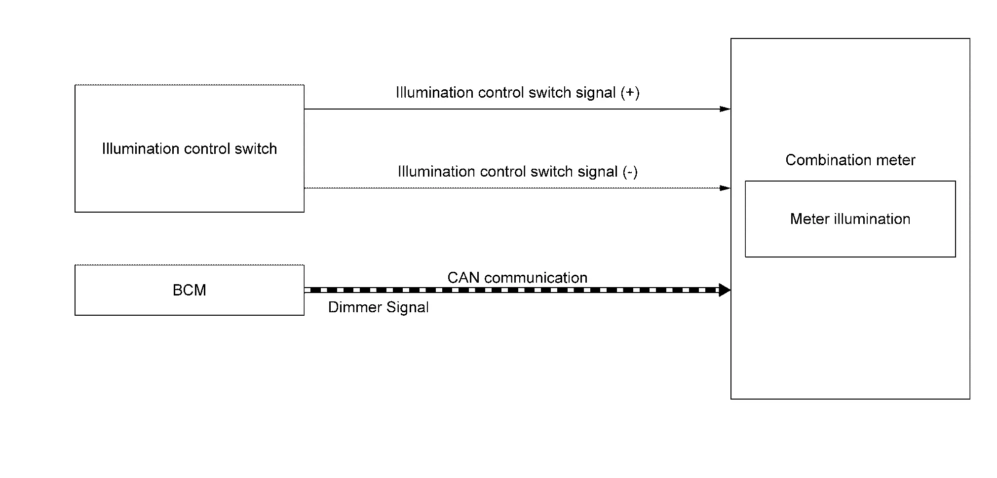
DESCRIPTION
Back Light Illumination Control Function
The operation of the illumination control switch allows the brightness adjustment of meter illumination.
| Meter illumination | The number of adjustable steps |
|---|---|
| Daytime | 22 step |
| Nighttime | 22 step |
Meter Illumination Control Function
-
Combination meter controls meter illumination, based on the dimmer signal.
-
When ignition is on the combination meter switches mode between Daytime mode and Nighttime mode, according to the following conditions.
Condition Meter illumination Combination switch
(lighting switch)1ST or 2ND position Outdoor: Bright* Daytime mode Outdoor: Dark* Nighttime mode AUTO POSITION Outdoor: Bright* Daytime mode Outdoor: Dark* Nighttime mode Off Daytime mode *: For further information, refer to System Description.
Signal Path
| Signal name | Signal path |
|---|---|
| Ignition signal | ŌĆö |
| Dimmer signal | BCM Combination meter |
Meter Effect Function
System Description
SYSTEM DIAGRAM
DESCRIPTION
Engine-start Effect Function
When recognizing an engine start, the combination meter controls the following items for producing the effect.
-
Speedometer
-
Tachometer
-
Information display
-
Meter illumination
Meter and Illumination Operations During Engine-start Effect
The combination meter controls the following items during the engine-start effect.
| Control item | Operation | |
|---|---|---|
| Speedometer | Sweeps the pointer. | |
| Tachometer | Sweeps the pointer. | |
| Illumination ring | Increases the brightness to the effect level in stages. | |
| Pointers | Turns on the illumination at the effect level. | |
| Information display | Display the animation. | |
NOTE:
The pointers are stopped and illumination is turned off while cranking the engine.
Engine Start Judgement
The combination meter judges ŌĆ£engine-startŌĆØ and activates the engine-start effect only once when the following operational conditions are all satisfied.
| Operational condition | |
|---|---|
| Ignition switch | ON position |
| Nissan Ariya Vehicle speed | Less than 1 km/h (0.6 MPH) |
| Engine state | After cranking the engine |
| Setting (Integral switch) | The setting of ŌĆ£Display EffectŌĆØ is ŌĆ£OnŌĆØ |
NOTE:
The engine-start effect exits when any of the above operational conditions is cancelled during the engine-start effect.
Signal Path
The combination meter judges ŌĆ£engine-startŌĆØ, according to the following signals and activates the engine-start effect function.
| Signal name | Signal source |
|---|---|
| Ignition signal | ŌĆö |
| Engine status signal | ECM Combination meter |
| Nissan Ariya Vehicle speed display signal | ECM Combination meter |
| Starter relay status signal | IPDM E/R Combination meter |
NOTE:
The engine-start effect function ends if any one of the above conditions is lost during the activation of this function.
Information Display
System Description
SYSTEM DIAGRAM
DESCRIPTION
-
The combination meter receives signals necessary for controlling the operation of the information display from each unit, sensor and switch.
-
The combination meter incorporates a trip computer that displays the warning/information according to the information received from each unit, sensor and switch.
-
The combination meter shows the following functions on the information display.
-
Warning/Indicator
-
Warning confirmation
-
Setting
-
Trip computer
-
Personal display
-
Meter illumination level
-
-
The items that displayed to information display can be selected by the steering switch, and illumination control switch. For further details, Refer to Steering Switch or Illumination Control Switch.
WARNING/INDICATOR LIST
| Warning | Reference |
|---|---|
| Headlamp warning | Refer to Headlamp Warning. |
| Light reminder warning | Refer to Light Reminder Warning (Information Display). |
| Washer fluid warning | Refer to Washer fluid warning. |
| AWD warning | Refer to AWD Warning. |
| Door open warning | Refer to Door Open Warning. |
| Intelligent Key low battery warning | Refer to Intelligent Key Low Battery Warning. |
| Intelligent Key system malfunction | Refer to Intelligent Key System Malfunction. |
| Take away warning | Refer to Take Away Warning (Information Display). |
| Chassis control warning | Refer to Chassis control warning. |
| Parking brake warning | Refer to Parking Brake Warning. |
| Automatic brake hold warning | Refer to Automatic Brake Hold Warning. |
| Low tire pressure warning | Refer to Low Tire Pressure Warning. |
| Low fuel warning | Refer to Low fuel warning. |
| Engine warning | Refer to Engine warning. |
| Electric shift warning | Refer to Electric Shift Warning. |
| CVT system warning | Refer to CVT System Warning. |
| Oil Level Warning | Refer to Oil Level Warning. |
| Shift P warning | Refer to Shift P Warning. |
| Indicator | Reference |
|---|---|
| Shift position indicator | Refer to Shift Position Indicator. |
| Neutral hold mode indicator | Refer to Neutral Hold Mode Indicator. |
| Remote engine start information | Refer to Remote Engine Start Information. |
| AWD torque distribution indicator | Refer to AWD Torque Distribution Indicator. |
| Engine start information | Refer to Engine Start Information. |
| Key ID verification information | Refer to Key ID Verification Information. |
| Audio indicator | Refer to System Description. |
| Hands-free phone indicator | Refer to System Description. |
| Sonar indicator | Refer to System Description. |
| Driving position memory | Refer to Driving Position Memory. |
| Tire pressure display | Refer to Tire Pressure Display. |
| Drive mode indicator | Refer to Drive Mode Indicator. |
| ASCD indicator | Refer to Indicator/Information. |
| Oil control system (OCS) indicator | Refer to Indicator/Information. |
| Alert | Refer to Alert. |
| Maintenance | Refer to Maintenance. |
| Low outside temperature display | Refer to Low outside temperature display. |
WARNING CONFIRMATION
-
The combination meter can cause an interrupt on the information display to indicate a warning, based on signals received from each unit and switch.
-
The indicated warning can be checked with ŌĆ£WARNINGŌĆØ during the satisfaction of an interrupt indication condition for each warning.
SETTINGS
The condition of following items can be set.
-
VDC Setting
-
Driver Assistance
-
Personal Display
-
Head-Up Display
-
ECO Mode Setting
-
TPMS Setting
-
Clock
-
Nissan Ariya Vehicle Settings
-
Maintenance
-
Customize Display
-
Unit/Language
-
Factory Reset
TRIP COMPUTER
Current Fuel Consumption
The combination meter calculates current fuel consumption based on the following signals, and the calculated value is displayed on the information display.
Current fuel consumption can be compared with average fuel consumption.
| Signal name | Signal source |
|---|---|
| Ignition signal | ŌĆö |
| Fuel consumption monitor signal | ECM Combination meter |
| Nissan Ariya Vehicle speed display signal | ECM Combination meter |
NOTE:
-
Current fuel consumption on the information display is updated approximately every 0.1 seconds.
-
Current fuel consumption on the information display shows 30 l/100km (0 mpg) when Nissan Ariya vehicle speed is 0 km/h (0 MPH).
Average Fuel Consumption
The combination meter calculates average fuel consumption based on the following signals, and the calculated value is displayed on the information display.
| Signal name | Signal source |
|---|---|
| Ignition signal | ŌĆö |
| Fuel consumption monitor signal | ECM Combination meter |
| Nissan Ariya Vehicle speed display signal | ECM Combination meter |
NOTE:
-
Average fuel consumption on the information display is updated approximately every 30 seconds.
-
Soon after a reset or when placing the ignition switch ON, ŌĆ£ŌłÆŌłÆŌłÆŌĆØ is displayed until after a travel of 30 seconds and approximately 500 m (0.31 mile).
Current Vehicle Speed
The combination meter calculates current vehicle speed based on the following signals, and the calculated value is displayed on the information display.
| Signal name | Signal path |
|---|---|
| Ignition signal | ŌĆö |
| Nissan Ariya Vehicle speed display signal | ECM Combination meter |
NOTE:
Current vehicle speed on the information display is updated approximately every 0.3 seconds.
Average Vehicle Speed
The combination meter calculates average vehicle speed based on the following signals, and the calculated value is displayed on the information display.
| Signal name | Signal source |
|---|---|
| Ignition signal | ŌĆö |
| Nissan Ariya Vehicle speed display signal | ECM Combination meter |
NOTE:
-
Average vehicle speed on the information display is updated approximately every 30 seconds.
-
Soon after a reset, ŌĆ£ŌłÆŌłÆŌłÆŌĆØ is displayed until after 30 seconds.
Travel Time
The combination meter measures and displays travel time (ignition switch ON time).
Travel Distance
The combination meter measures and displays travel distance.
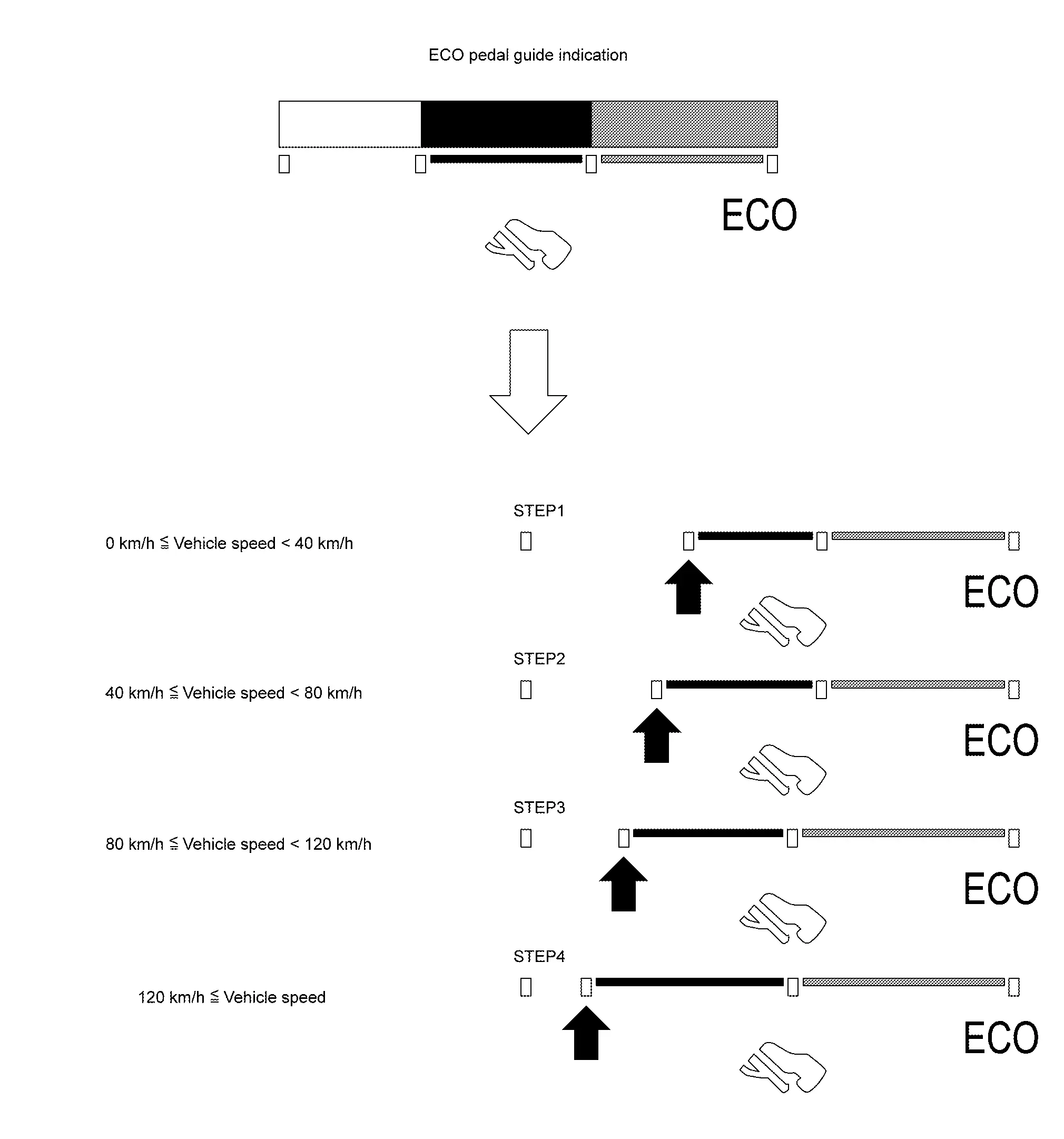
ECO Pedal Guide
The ECO pedal guide consists of Gauge 1  (displays accelerator pedal angle) and Gauge 2
  (displays the guideline of ECO driving).
GAUGE1
-
ECM corrects the accelerator pedal angle to the maximum angle for ECO driving, according to Nissan Ariya vehicle speeds.
The maximum accelerator pedal angle increases/decreases as the vehicle speed increases/decrease.
The maximum accelerator angle corrected by ECM is the limitation of ECO driving. The ECO driving is possible only when the number of unlit segments
of the indicator bar is equal to or less than that of Gauge 2.The less the number of unlit segments
of the indicator bar, the more the degree of ECO driving is. And the
more the number of unlit segments, the less the degree of ECO driving
is.
ECM judges the number of lighting segments according to the accelerator pedal angle and Nissan Ariya vehicle speed and transmits a CAN communication signal to the combination meter via CAN communication.
The combination meter indicates the number of segments necessary for the ECO pedal guide, according to an ECO pedal guide signal.
NOTE:
The combination meter corrects the number of lighting segments according to a Nissan Ariya vehicle speed signal.
GAUGE2
-
The combination meter turns ON/OFF the Gauge 2 (guide line for ECO driving) according to a Nissan Ariya vehicle speed signal.
ECO DRIVE INDICATOR
-
The combination meter displays level of ECO drive in conjunction with ECO pedal guide.
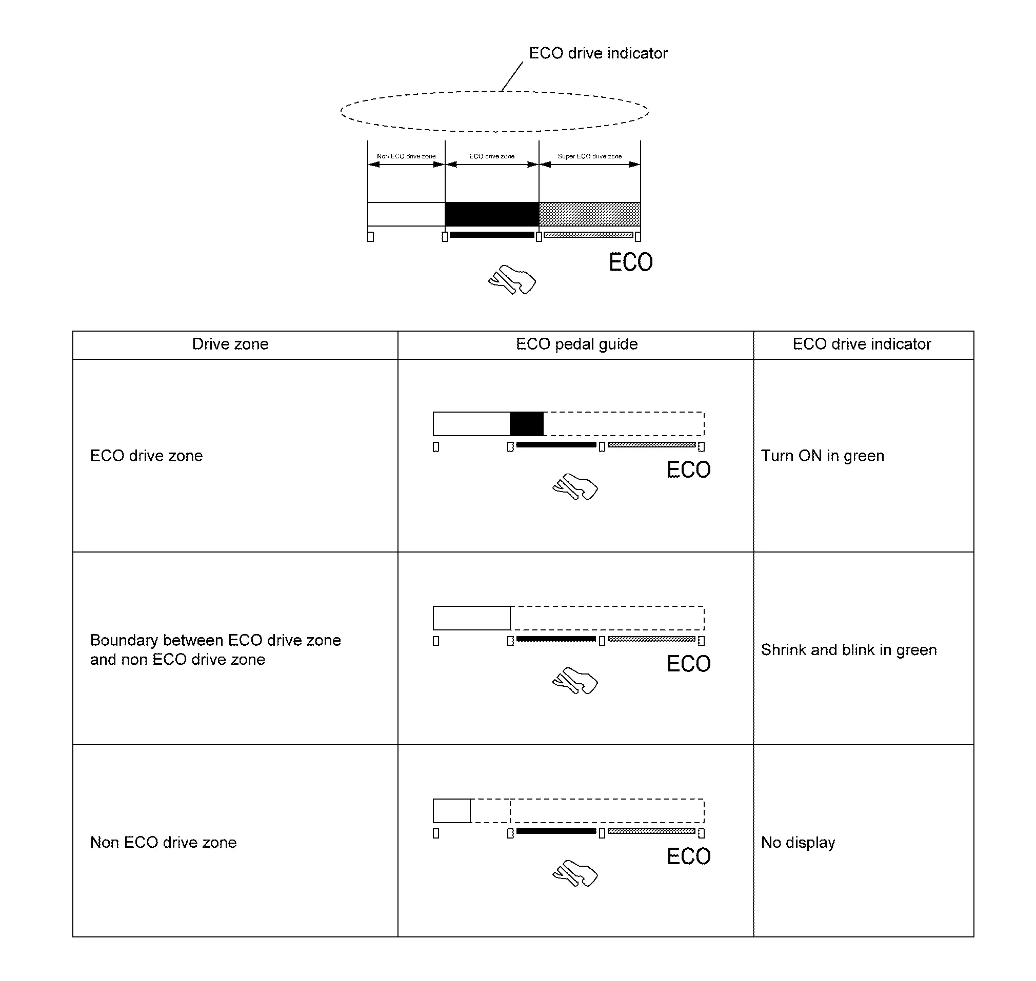
| Signal name | Signal path | |
|---|---|---|
| Ignition signal | ŌĆö | |
| ECO pedal guide signal | ECM Combination meter |
|
ECO Drive Report
-
The ECO drive report is a function which displays the last five data of average fuel consumption, present fuel economy (present value), and the best fuel economy (highest value) on the information display by calculating and recording average fuel consumption.
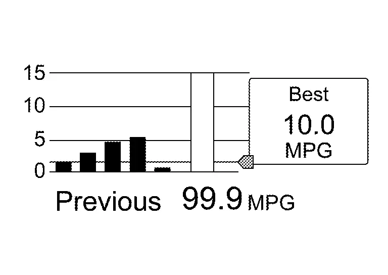
-
The combination meter calculates the average fuel consumption according to the signal below, detects the status of ECO mode , and displays ŌĆ£ECO drive reportŌĆØ on the information display when placing the ignition switch ONŌåÆOFF.
Signal name Signal path Ignition signal ŌĆö Fuel consumption monitor signal ECM Combination meter Nissan Ariya Vehicle speed display signal ECM Combination meter ECO mode indicator signal ECM Combination meter
PERSONAL DISPLAY
|
Enhance view
|
Classic view
|
The combination meter can displays the various information on personal display  .
.
The information displayed on the personal display can be selected by the combination meter setting menu.
METER ILLUMINATION LEVEL
The combination meter displays the illuminance level of the back light on the information display by turning the illumination control switch.
Refer to System Description.
Head up Display
System Description
SYSTEM DIAGRAM
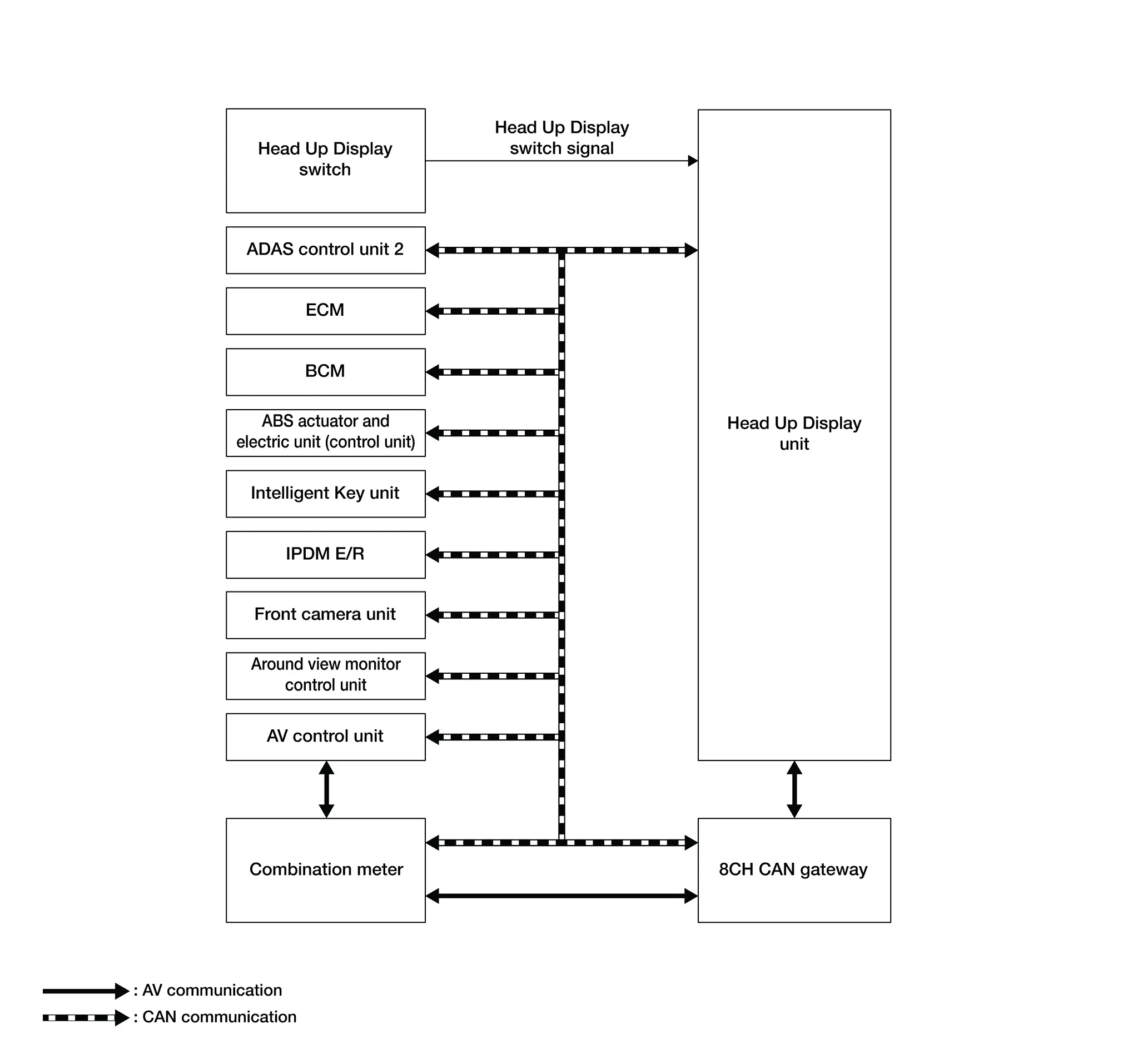
| Parts name | Description |
|---|---|
| Head Up Display unit | Refer to Head Up Display Unit. |
| Head Up Display switch | Refer to Head Up Display Switch. |
| ADAS control unit 2 | Transmits the display signal of drive assistance and warning to the Head up Display unit via CAN communication. |
| ECM | Transmits the ASCD status to the Head Up Display unit via CAN communication. |
| BCM |
Transmits the following signals to the Head Up Display unit via CAN communication.
|
| ABS actuator and electric unit (control unit) | Transmits the odometer signal to the Head Up Display unit via CAN communication. |
| Intelligent Key unit | Transmits the user identification signal to the Head Up Display unit via CAN communication. |
| IPDM E/R | Transmits the battery voltage signal to the Head Up Display unit via CAN communication. |
| AV control unit | Transmits the key link activation status signal to the Head Up Display unit via CAN communication. |
| Combination meter |
|
| 8CH CAN gateway | Transmits the signals between the Head Up Display unit and combination meter via AV communication. |
| Front camera unit | Transmits the display signal of drive assistance and warning to the Head up Display unit via CAN communication. |
| Around view monitor control unit | Transmits the display signal to the Head Up Display unit via CAN communication. |
Head Up Display Unit Input Signal
| Transmit unit | Signal name |
|---|---|
| ADAS control unit 2 | Display signal |
| ECM | ASCD status signal |
| BCM | Auto ACC status signal |
| Nissan Ariya Vehicle status signal | |
| ABS actuator and electric unit (control unit) | Odometer signal |
| Intelligent Key unit | User identification signal |
| IPDM E/R | Battery voltage signal |
| AV control unit | Key link activation status signal |
| Combination meter | Nissan Ariya Vehicle speed display signal |
| HUD setting signal | |
| Front camera unit | Display signal |
| Around view monitor control unit | Display signal |
| Transmit unit | Signal name |
|---|---|
| Combination meter | Navigation signal |
DESCRIPTION
-
The Head Up Display (HUD) displays information on the vehicle speed and driving assistance system on the windshield glass, and supports safe driving by suppressing the burden due to the movement of the driver's eyes.
-
The Head Up Display unit receives necessary signals from each ECU via CAN communication and local communication.
Operation
-
When the ignition switch is ON, pressing the main switch activates Head Up Display.
-
Head Up Display projects display on the windshield glass.
-
Image focus on 2.1 m (6.89 ft) from driver's eye point.
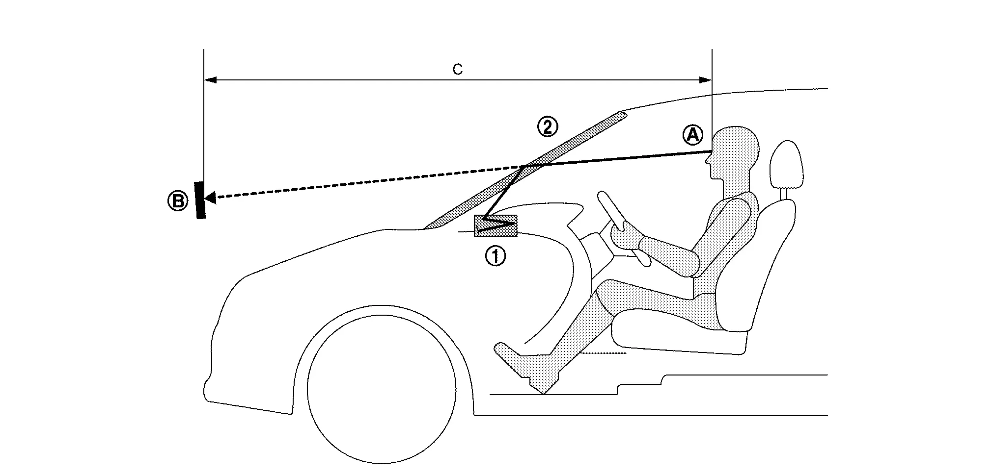
|
Head Up Display unit |  |
Windshield glass |
|
Eye point | |
Virtual image display |
| C. | 2.0 m (6.56 ft) |
Structure
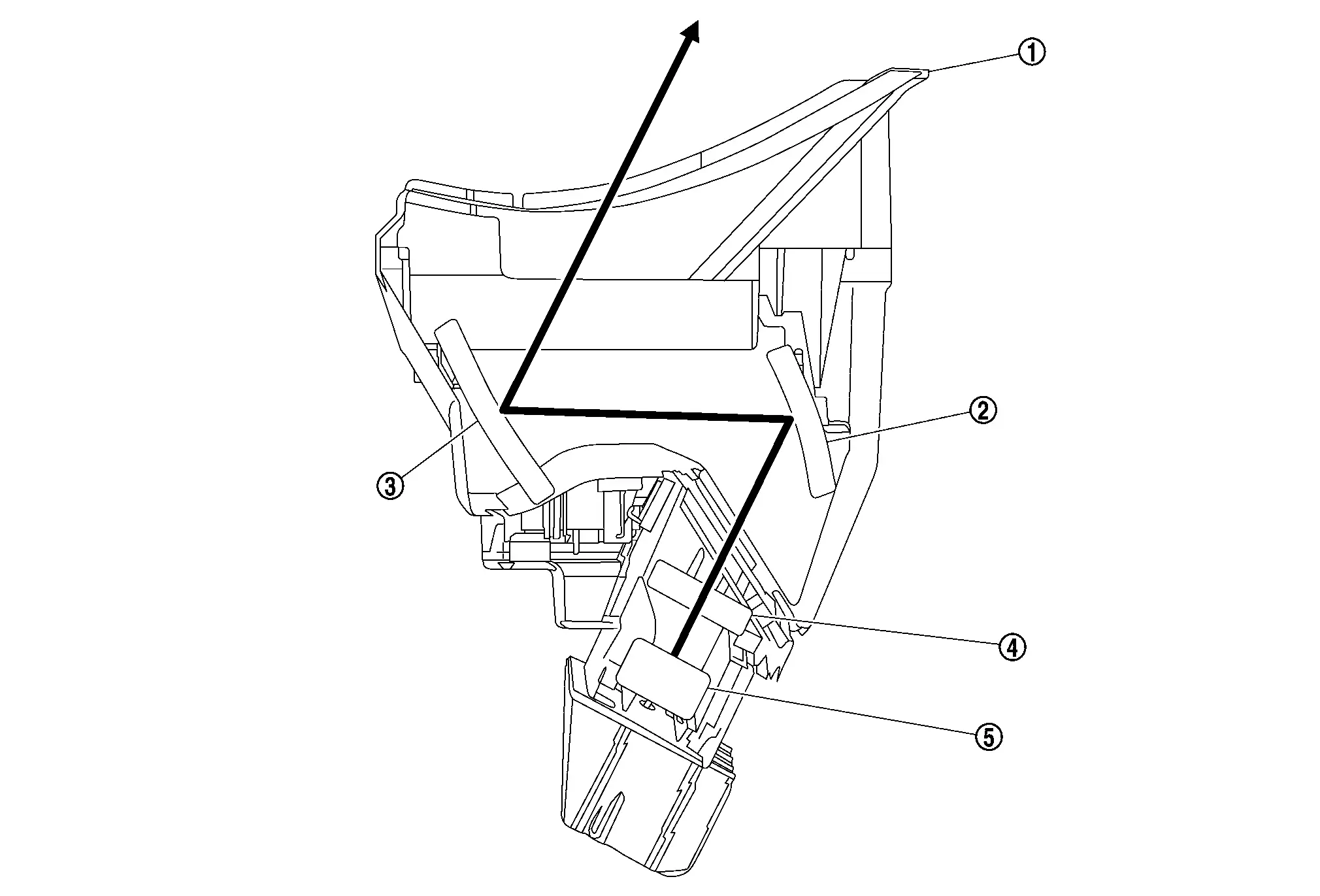
The Head Up Display unit projects the image to the windshield glass by reflecting the image of the TFT liquid crystal display on the concave mirror. Also, by manipulating the angle of the concave mirror, the projection position on the windshield glass can be adjusted.
|
Head Up Display unit | |
First mirror (Fixed mirror) |  |
Second mirror (Movable mirror) |
 |
TFT liquid crystal display |  |
Light source | ||
 |
: Projection path |
Display Item
-
The Head Up Display (HUD) can display one or more of the following features.
-
The Head Up Display unit can cause an interrupt on the HUD display to indicate a warning, based on signals received from each unit.
For U.S.A.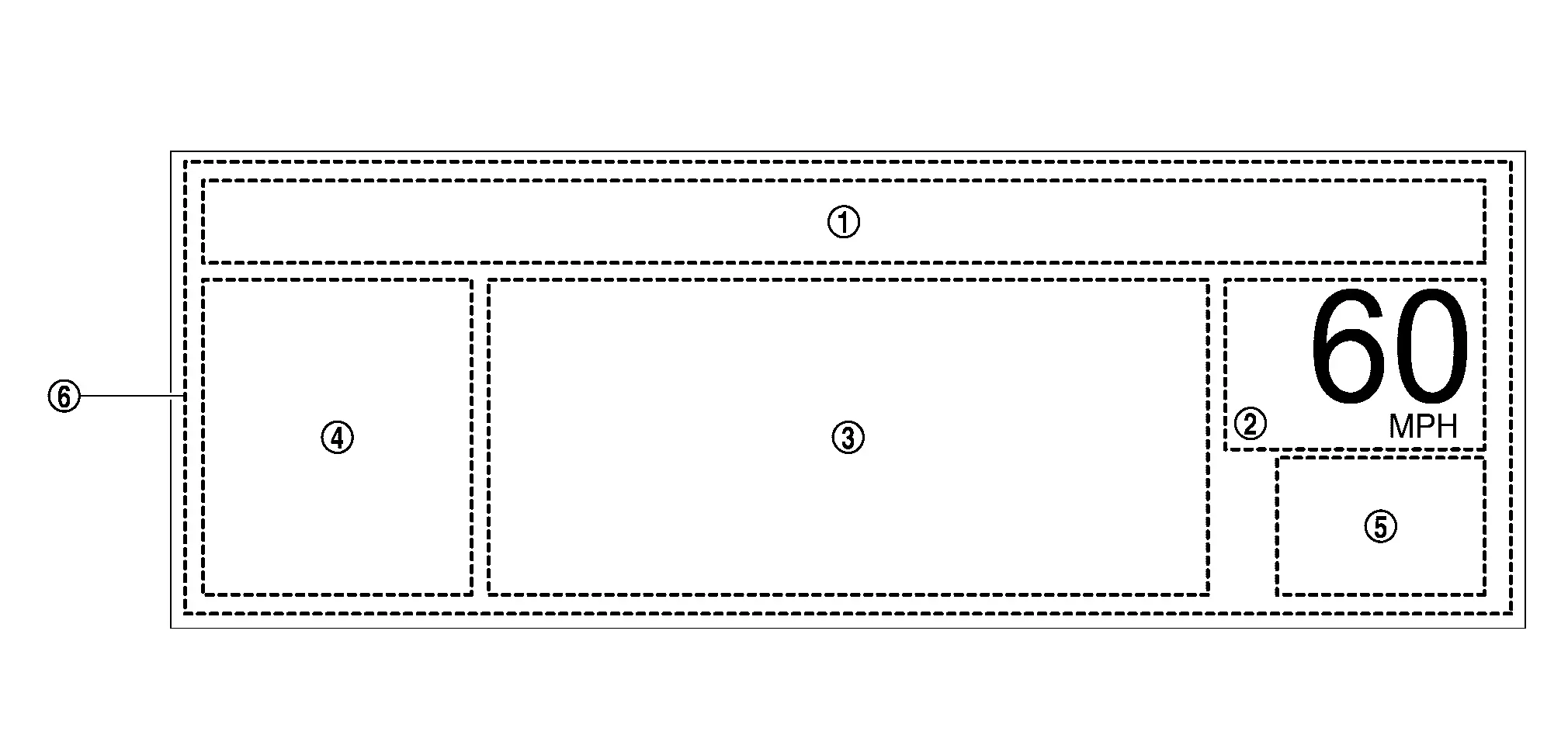
Except for U.S.A.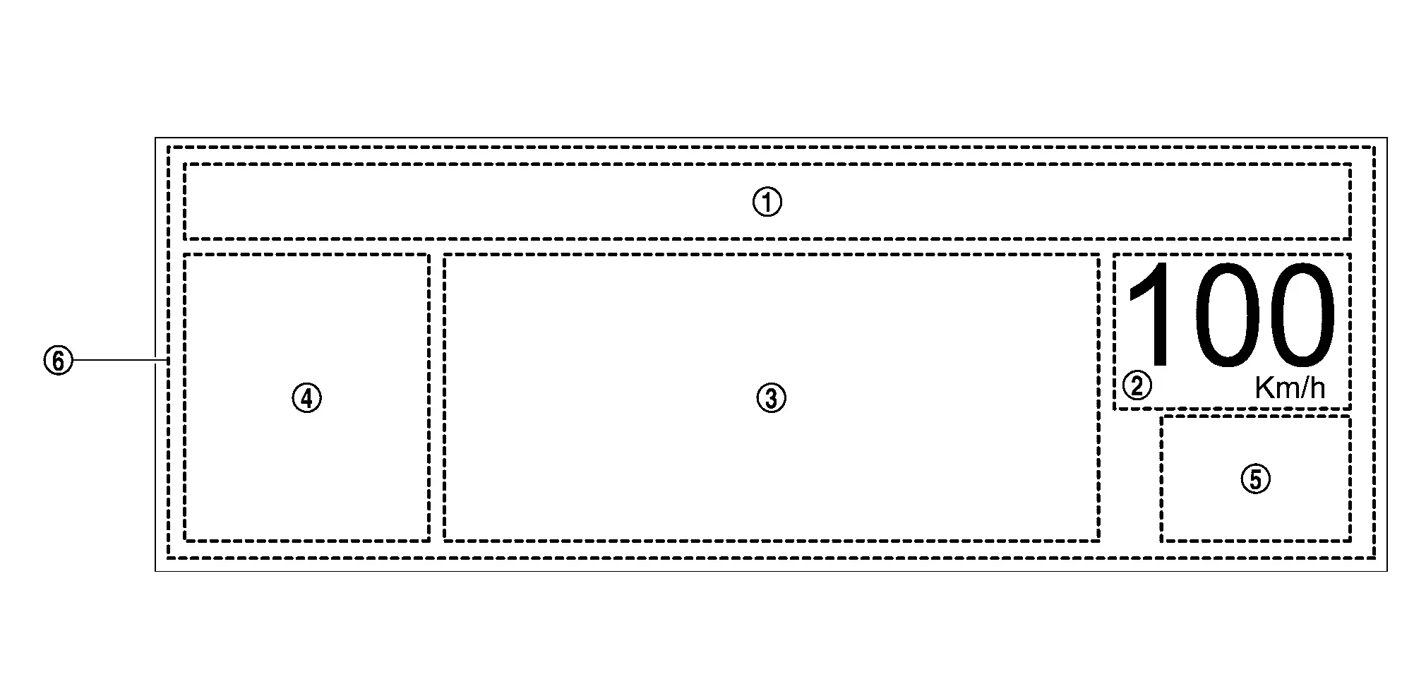
| No. | Display | Description | |
|---|---|---|---|
|
Message display |
|
|
|
Nissan Ariya Vehicle speed display | Always display the vehicle speed | |
|
Driving Aids | ASCD display | Displays setting Nissan Ariya vehicle speed during ASCD operation |
| ICC display | Displays information on setting Nissan Ariya vehicle speed and presence/absence of preceding vehicle during ICC operation | ||
| ProPILOT Assist system display | Displays setting ProPILOT Assist system status during ProPILOT Assist system operation | ||
| LDW system display | Displays LDW system display during LDW system operation | ||
| I-LI system display | Display I-LI system display during I-LI system operation | ||
| I-FCW system display | Display I-FCW display during I-FCW operation | ||
|
Turn by Turn display | Display arrows at intersection with navigation guidance and guide traveling direction | |
|
TSR system display | Display TSR system display during TSR system operation | |
 |
Interrupt display | ProPILOT Assist system warning display | Display ProPILOT Assist system display during ProPILOT Assist system operation |
| AEB warning display | Display AEB warning display during AEB operation | ||
| Turn by Turn display | Display arrows at intersection with navigation guidance and guide traveling direction | ||
| Audio operation display | Display audio operation display during audio switch operation | ||
NOTE:
-
The items displayed depend on vehicle specifications.
-
When placing the ignition switch ON, only Nissan Ariya vehicle speed is displayed.
-
Emergency information may display even if the Head Up Display is turned off.
-
The display position, display rotation, display brightness, and display setting adjustment of the Head Up Display can be set on the setting screen of the combination meter. Refer to Switch Name and Function.
Automatic Dimming Function
The Head Up Display unit reads the illuminance sensor value and adjusts the brightness of the display automatically.
NOTE:
The brightness of the display can be manually adjusted on the combination meter setting screen. Refer to Switch Name and Function.
Protection Function
LED protection function
The Head Up Display unit monitors the LED display temperature, and limits and protects the brightness of the backlight when the LED temperature becomes high temperature.
| Conditions | Function | Cancellation condition | |
|---|---|---|---|
| Head Up Display unit LED temperature | 120 ┬░C (248 ┬░F ) or higher | Decrease backlight brightness according to temperature rise | 105 ┬░C (221 ┬░F) or lower |
| 145 ┬░C (293 ┬░F) or higher | Completely turn off | ||
Other materials:
Symptom Diagnosis. Squeak and Rattle Trouble Diagnoses
Work Flow
CUSTOMER INTERVIEWInterview
the customer if possible, to determine the conditions that exist when
the noise occurs. Use the Diagnostic Worksheet during the interview to
document the facts and conditions when the noise occurs and any of
customer's comments. Refer to Diagnostic Work ...
U0644 Sent Communication
DTC Description
DTC DETECTION LOGIC DTC No.
CONSULT screen terms
(Trouble diagnosis content) DTC detecting condition
U0644
00
Lost comm with w/g posi sen (b1)
(Lost Communication With Wastegate Position Sensor "A")
Diagnosis condition
Battery voltage: 8 V or more
Igni ...
P34c8 Electric Intake Valve Timing Control Module
DTC Description
DTC DETECTION LOGIC DTC
CONSULT screen terms
(Trouble diagnosis content)
DTC detection condition
P34C8
00
Camshaft position control module
(Camshaft position control module performance)
Diagnosis condition
Ignition switch ON
Signal (terminal)
ŌĆö
...