Nissan Rogue (T33) 2021-Present Service Manual: Component Parts
Meter System
Component Parts Location
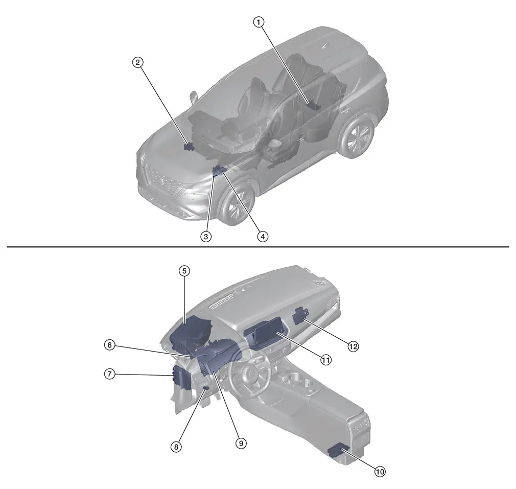
2WD MODELS
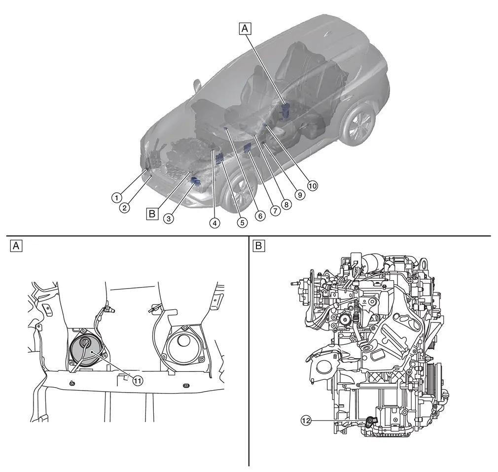
| A. | View with rear seat removed | B. | View with engine assembly removed |
| No. | Component | Function |
|---|---|---|
| 1. | Washer fluid level switch (if so equipped) |
Transmits the washer fluid level switch signal to the combination meter. Refer to Component Parts Location for detailed component location. |
| 2. | Ambient sensor | Refer to Ambient Sensor. |
| 3. | TCM (Transmission Control Module) |
Transmits each signal to the combination meter via CAN communication. Refer to Component Parts Location for detailed component location. |
| 4. | Brake fluid level switch |
Transmits the brake fluid level switch signal to the combination meter. Refer to Component Parts Location for detailed component location. |
| 5. | ECM (Engine Control Module) |
Transmits each signal to the combination meter via CAN communication. Refer to Component Parts Location for detailed component location. |
| 6. | Meter speaker | Refer to Meter Speaker. |
| 7. | BCM (Body Control Module) |
Based on the signals received from various units and switches, transmits the buzzer output signal to the combination meter via CAN communication. Refer to Component Parts Location for detailed component location. |
| 8. | Combination meter | Refer to Combination Meter. |
| 9. | Illumination control switch | Refer to Illumination Control Switch. |
| 10. | Steering switches | Refer to Steering Switches. |
| 11. | Fuel level sensor unit, fuel pump and FPCM (Fuel Pump Control Module) (fuel level sensor) (main) | Refer to Fuel Level Sensor Unit, Fuel Pump and FPCM (Fuel Level Sensor)(Main) - 2WD Models. |
| 12. | Oil level sensor | Refer to Oil Level Sensor. |
AWD MODELS
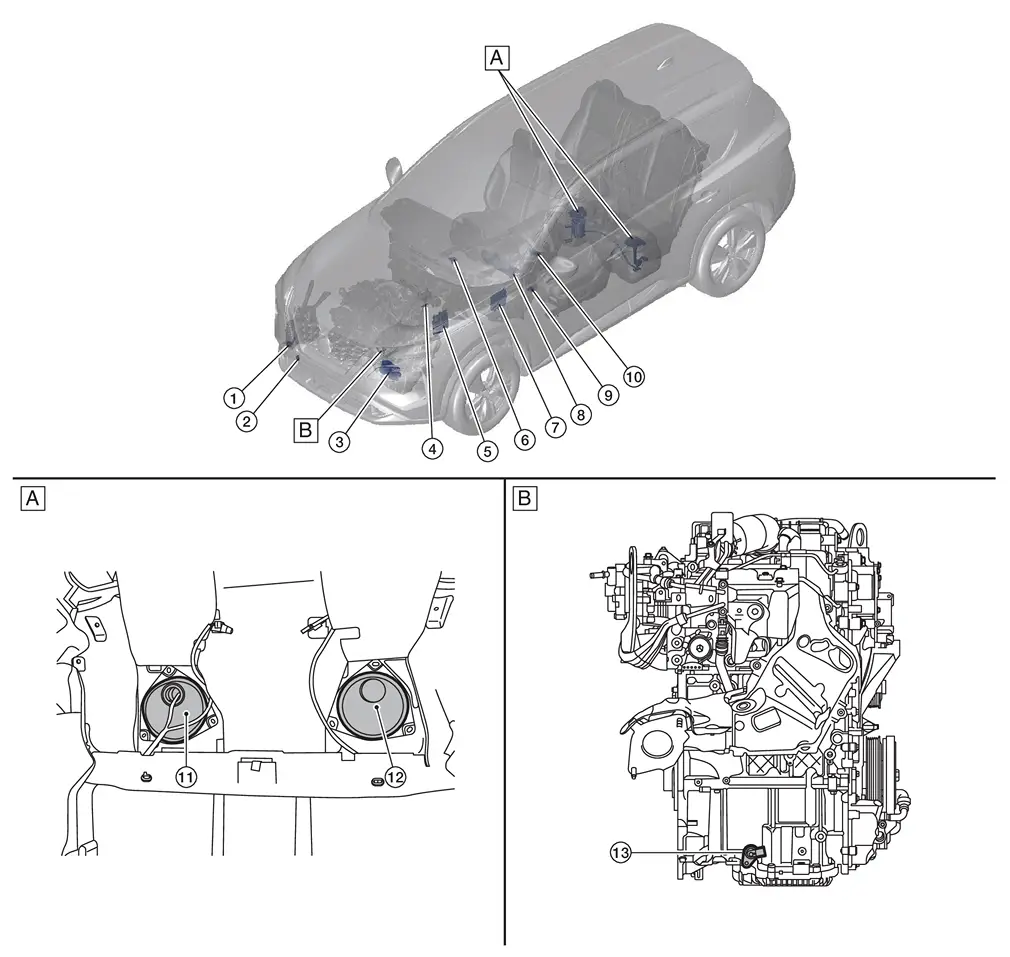
| A. | View with rear seat removed | B. | View with engine assembly removed |
| No. | Component | Function |
|---|---|---|
| 1. | Washer fluid level switch (if so equipped) |
Transmits the washer fluid level switch signal to the combination meter. Refer to Component Parts Location for detailed component location. |
| 2. | Ambient sensor | Refer to Ambient Sensor. |
| 3. | TCM (Transmission Control Module) |
Transmits each signal to the combination meter via CAN communication. Refer to Component Parts Location for detailed component location. |
| 4. | Brake fluid level switch |
Transmits the brake fluid level switch signal to the combination meter. Refer to Component Parts Location for detailed component location. |
| 5. | ECM (Engine Control Module) |
Transmits each signal to the combination meter via CAN communication. Refer to Component Parts Location for detailed component location. |
| 6. | Meter speaker | Refer to Meter Speaker. |
| 7. | BCM (Body Control Module) |
Based on the signals received from various units and switches, transmits the buzzer output signal to the combination meter via CAN communication. Refer to Component Parts Location for detailed component location. |
| 8. | Combination meter | Refer to Combination Meter. |
| 9. | Illumination control switch | Refer to Illumination Control Switch. |
| 10. | Steering switches | Refer to Steering Switches. |
| 11. | Fuel level sensor unit, fuel pump and FPCM (Fuel Pump Control Module) (fuel level sensor) (main) | Refer to Fuel Level Sensor Unit, Fuel Pump and FPCM (Fuel Level Sensor)(Main) and Fuel Level Sensor Unit (Sub) - AWD Models. |
| 12. | Fuel level sensor unit (sub) | Refer to Fuel Level Sensor Unit, Fuel Pump and FPCM (Fuel Level Sensor)(Main) and Fuel Level Sensor Unit (Sub) - AWD Models. |
| 13. | Oil level sensor | Refer to Oil Level Sensor. |
Design
ARRANGEMENT OF COMBINATION METER
ENHANCE VIEW
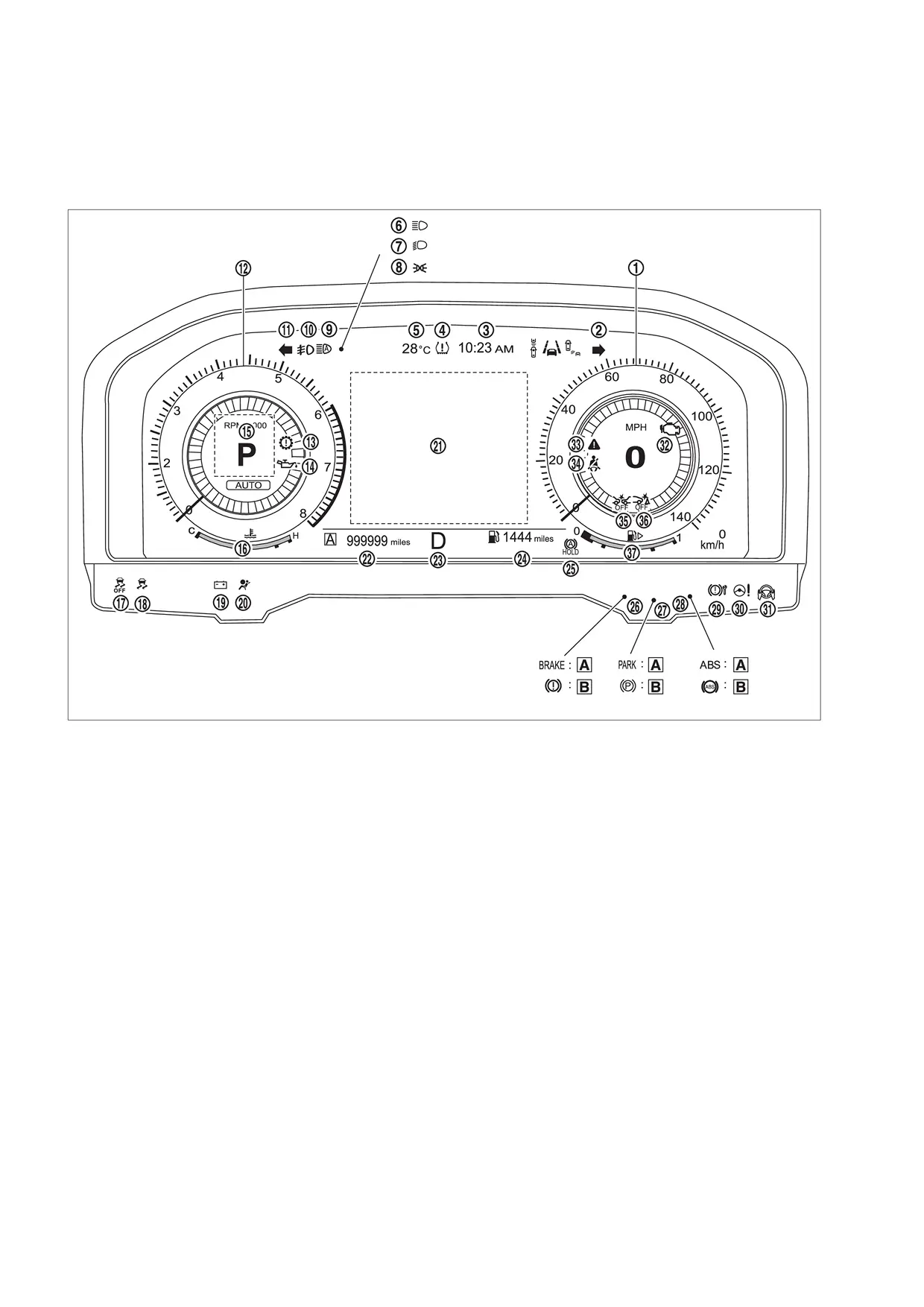
| A | For U.S.A. | B | Except for U.S.A. | ã | ã |
| No. | Indicator lamp/Warning lamp | Color | Function |
|---|---|---|---|
| 1. | Speedometer | ã | Refer to System Description. |
| 2. | Turn signal indicator lamp (RH) | Green | Refer to Turn Signal Indicator Lamp. |
| 3. | Clock | ã | Refer to System Description. |
| 4. | Low tire pressure warning lamp | Yellow | Refer to Low Tire Pressure Warning Lamp. |
| 5. | Ambient temperature | ã | Refer to System Description. |
| 6. | High beam indicator lamp | Green | Refer to High Beam Indicator Lamp. |
| 7. | Dipped beam indicator lamp | Green | Refer to Dipped Beam Indicator Lamp. |
| 8. | Position lamp indicator lamp | Green | Refer to Position Lamp Indicator Lamp. |
| 9. | High beam assist indicator lamp | Green | Refer to High Beam Assist Indicator Lamp . |
| 10. | Front fog lamp indicator lamp | Green | Refer to Front Fog Lamp Indicator Lamp. |
| 11. | Turn signal indicator lamp (LH) | Green | Refer to Turn Signal Indicator Lamp. |
| 12. | Tachometer | ã | Refer to System Description. |
| 13. | Electric shift warning lamp | Red | Refer to Electric Shift Warning Lamp. |
| 14. | Engine oil pressure warning lamp | Red | Refer to Engine Oil Pressure Warning Lamp. |
| 15. | Personal display | ã | Refer to System Description. |
| 16. | Engine coolant temperature gauge | ã | Refer to System Description. |
| 17. | VDC OFF indicator lamp | Yellow | Refer to VDC OFF Indicator Lamp. |
| 18. | VDC warning lamp | Yellow | Refer to VDC Warning Lamp. |
| 19. | 12V Battery Charge warning lamp | Red | Refer to 12V Battery Charge Warning Lamp. |
| 20. | SRS air bag warning lamp | Red | Refer to SRS Air Bag Warning Lamp. |
| 21. | Information display | ã | Refer to System Description. |
| 22. | Odometer | ã | Refer to System Description. |
| 23. | Shift position indicator | ã | Refer to System Description. |
| 24. | Distance to empty | ã | Refer to System Description. |
| 25 | Automatic brake hold indicator lamp | White/ Green | Refer to Automatic Brake Hold Indicator Lamp. |
| 26. | Brake warning lamp | Red | Refer to Brake Warning Lamp. |
| 27. | Electric parking brake indicator lamp | Red | Refer to Electric Parking Brake Indicator Lamp. |
| 28. | ABS warning lamp | Yellow | Refer to ABS Warning Lamp. |
| 29. | Electric parking brake warning lamp | Yellow | Refer to Electric Parking Brake Warning Lamp. |
| 30. | Electric power steering warning lamp | Yellow | Refer to Power Steering Warning Lamp. |
| 31. | Hands OFF warning lamp | Red | Refer to Hands OFF Warning Lamp. |
| 32. | Malfunction indicator lamp (MIL) | Yellow | Refer to Malfunction Indicator Lamp (MIL). |
| 33. | Master warning lamp | Yellow/Red | Refer to Master Warning Lamp. |
| 34. | Seat belt warning lamp | Red | Refer to Seat Belt Warning Lamp. |
| 35. | AEB warning lamp | Yellow | Refer to AEB Warning Lamp. |
| 36. | RAB warning lamp | Yellow | Refer to RAB Warning Lamp . |
| 37. | Fuel gauge | ã | Refer to System Description. |
CLASSIC VIEW
| A | For U.S.A. | B | Except for U.S.A. | ã | ã |
| No. | Indicator lamp/Warning lamp | Color | Function |
|---|---|---|---|
| 1. | Speedometer | ã | Refer to System Description. |
| 2. | Turn signal indicator lamp (RH) | Green | Refer to Turn Signal Indicator Lamp. |
| 3. | Clock | ã | Refer to System Description. |
| 4. | Low tire pressure warning lamp | Yellow | Refer to Low Tire Pressure Warning Lamp. |
| 5. | Ambient temperature | ã | Refer to System Description. |
| 6. | High beam indicator lamp | Green | Refer to High Beam Indicator Lamp. |
| 7. | Dipped beam indicator lamp | Green | Refer to Dipped Beam Indicator Lamp. |
| 8. | Position lamp indicator lamp | Green | Refer to Position Lamp Indicator Lamp. |
| 9. | High beam assist indicator lamp | Green | Refer to High Beam Assist Indicator Lamp . |
| 10. | Front fog lamp indicator lamp | Green | Refer to Front Fog Lamp Indicator Lamp. |
| 11. | Turn signal indicator lamp (LH) | Green | Refer to Turn Signal Indicator Lamp. |
| 12. | Tachometer | ã | Refer to System Description. |
| 13. | Electric shift warning lamp | Red | Refer to Electric Shift Warning Lamp. |
| 14. | Engine oil pressure warning lamp | Red | Refer to Engine Oil Pressure Warning Lamp. |
| 15. | Personal display | ã | Refer to System Description. |
| 16. | Engine coolant temperature gauge | ã | Refer to System Description. |
| 17. | VDC OFF indicator lamp | Yellow | Refer to VDC OFF Indicator Lamp. |
| 18. | VDC warning lamp | Yellow | Refer to VDC Warning Lamp. |
| 19. | 12V Battery Charge warning lamp | Red | Refer to 12V Battery Charge Warning Lamp. |
| 20. | SRS air bag warning lamp | Red | Refer to SRS Air Bag Warning Lamp. |
| 21. | Information display | ã | Refer to System Description. |
| 22. | Odometer | ã | Refer to System Description. |
| 23. | Shift position indicator | ã | Refer to System Description. |
| 24. | Distance to empty | ã | Refer to System Description. |
| 25 | Automatic brake hold indicator lamp | White/ Green | Refer to Automatic Brake Hold Indicator Lamp. |
| 26. | Brake warning lamp | Red | Refer to Brake Warning Lamp. |
| 27. | Electric parking brake indicator lamp | Red | Refer to Electric Parking Brake Indicator Lamp. |
| 28. | ABS warning lamp | Yellow | Refer to ABS Warning Lamp. |
| 29. | Electric parking brake warning lamp | Yellow | Refer to Electric Parking Brake Warning Lamp. |
| 30. | Electric power steering warning lamp | Yellow | Refer to Power Steering Warning Lamp. |
| 31. | Hands OFF warning lamp | Red | Refer to Hands OFF Warning Lamp. |
| 32. | Malfunction indicator lamp (MIL) | Yellow | Refer to Malfunction Indicator Lamp (MIL). |
| 33. | Master warning lamp | Yellow/Red | Refer to Master Warning Lamp. |
| 34. | Seat belt warning lamp | Red | Refer to Seat Belt Warning Lamp. |
| 35. | AEB warning lamp | Yellow | Refer to AEB Warning Lamp. |
| 36. | RAB warning lamp | Yellow | Refer to RAB Warning Lamp . |
| 37. | Fuel gauge | ã | Refer to System Description. |
Combination Meter
Component Function Within The System
The combination meter controls the following items according to the signals received from each unit via CAN communication and the signals from switches and sensors.
-
Measuring instruments
-
Speedometer
-
Tachometer
-
Engine coolant temperature gauge
-
Fuel gauge
-
Odometer
-
Distance to empty
-
Clock
-
Ambient temperature
-
-
Indicator lamps
-
Warning lamps
-
Meter illumination control
-
Meter effect function
-
Information display
CLOCK SPECIFICATIONS
| Operating voltage | (V) | 11 - 16 |
| Accuracy | (sec./day) | Approx. ôÝ 6 |
 NOTE:
NOTE:
The time is displayed on the information display. When a time lag of more than the above described accuracy occurs, the combination meter battery power supply voltage may be low. In this case, check 12V battery for malfunction causing low power supply voltage. Models with the navigation system are free of time lag resulted from low power supply voltage because of the synchronization with GPS signals.
Individual Component Function
Combination meter indicates the condition of the vehicle.
Component Operation
Refer to System Description.
Component Parts Location
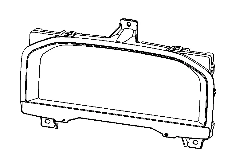
Combination meter is installed to the cluster lid A.
Refer to Component Parts Location.
Meter Speaker
Component Function Within The System
-
Output meter sound by meter speaker signal from combination meter.
Individual Component Function
Sound signals generated by the combination meter output sounds.
| Size | (öÎ) | 4.6 cm (1.8 in) |
| Rated input | (W) | 1.5 |
| MAX input | (W) | 3 |
| Impedance | (öˋ) | 8 |
Component Operation
Meter speaker signals are input to the speaker, and sound is output.
Component Parts Location
-
The meter speaker is located on the instrument panel. Refer to Component Parts Location.
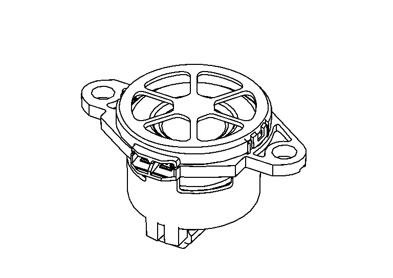
Steering Switches
Component Function Within The System
Screen of information display can be switched by operating the steering switch.
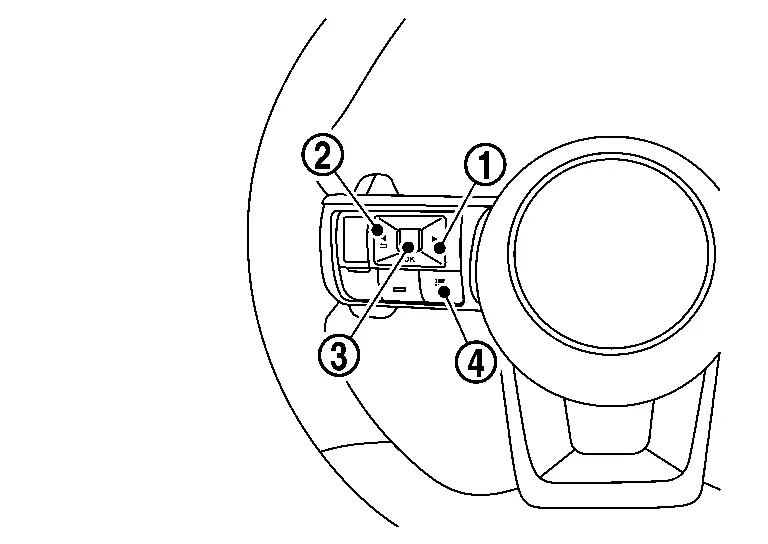
| No. | Switch name | Operation | Description | |
|---|---|---|---|---|
 |
RIGHT switch | Press | Switches the screen shown on the information display. | |
 |
LEFT/BACK switch | Press |
|
|
 |
OK switch | Press | Switches the screen shown on the information display. | |
| Jog dial | Up |
|
||
| Down |
|
|||
 |
Control switch | Press | Switches the screen shown on the information display to the short cut menu screen. | |
Individual Component Function
Steering switch inputs a switch status to the combination meter.
Component Operation
-
The steering switch consists of combination of normally open switches and resistors.
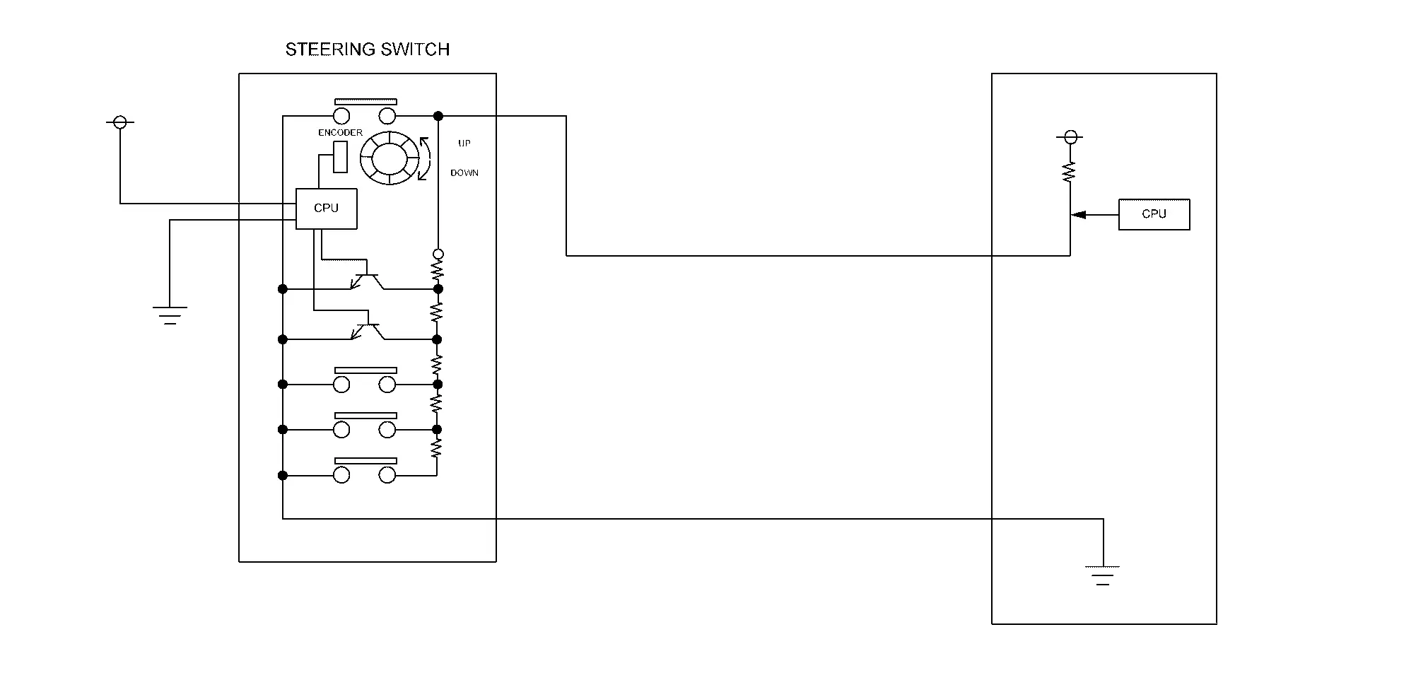
-
When each switch is pressed, the voltage from the combination meter is displaced according to the resistance value set for each switch, and the combination meter reads which switch is pressed.
-
Combination meter reads a switch state by an electric potential change.
Component Parts Location
Steering switch for the combination meter is installed to the left side of steering wheel. Refer to Component Parts Location.
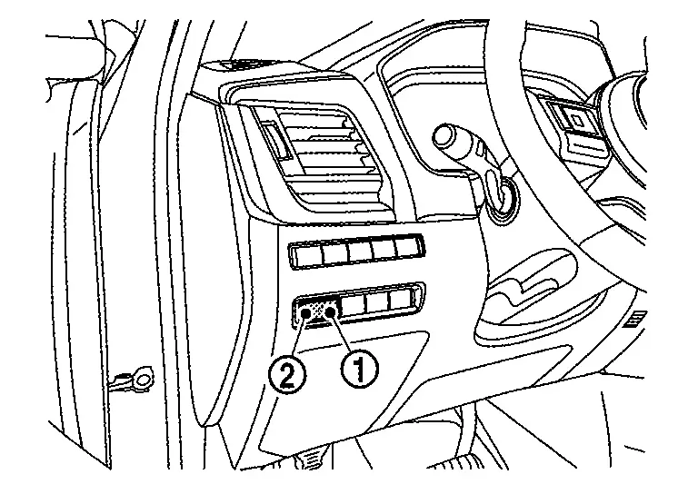
Illumination Control Switch
Component Function Within The System
The brightness of combination meter and information display can be adjusted by pressing the illumination control switch (+/ã)
| No. | Switch name | Operation | Description |
|---|---|---|---|
|
Illumination control switch (+) | Press | The brightness of combination meter and information display can be adjusted. |
|
Illumination control switch (ã) |
Individual Component Function
Transmits the illumination control switch signal to the combination meter.
Component Operation
-
Adopted momentary switch.
 NOTE:
NOTE:
Momentary switch: While push the switch, it becomes ON and returns to an OFF state when release the switch.
-
Change switch operation into ON (0 V) / OFF (10 V) of the voltage.
-
Combination meter reads a switch state by an electric potential change.
Component Parts Location
The illumination control switch is located on the instrument lower panel LH. Refer to Component Parts Location.
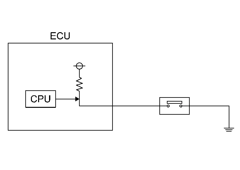
Ambient Sensor
Component Function Within The System
-
Ambient sensor measures ambient air temperature.
-
Ambient sensor transmits the ambient sensor signal to the combination meter.
Individual Component Function
Ambient sensor measures ambient air temperature.
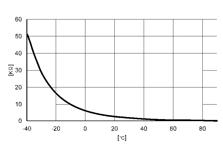
Component Operation
Ambient sensor uses a thermistor which is sensitive to the change in temperature. The electrical resistance of the thermistor decreases as temperature increases.
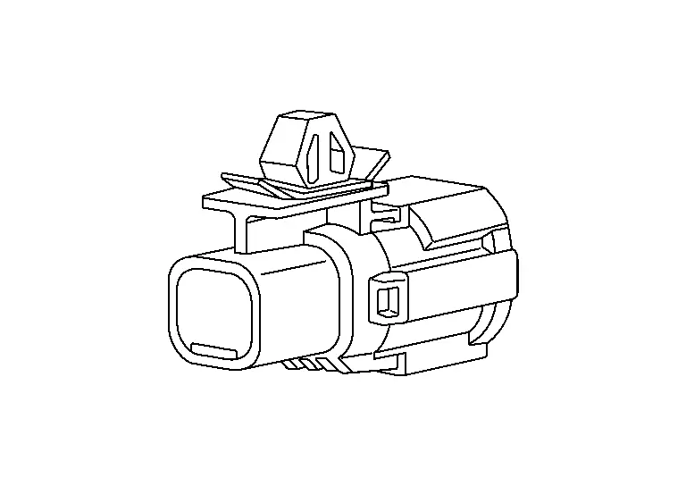
Component Parts Location
Ambient sensor is installed to back side of the front bumper. Refer to Component Parts Location.
Oil Level Sensor
Component Function Within The System
Oil level sensor transmits the low oil level sensor signal to the combination meter.
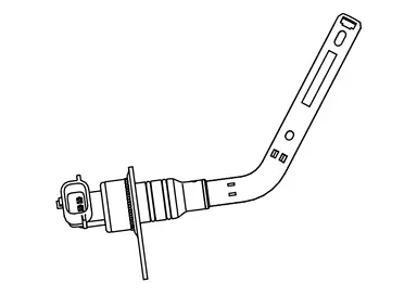
Individual Component Function
Oil level sensor detects low engine oil level.
Component Parts Location
The oil level sensor is installed to the cylinder block. Refer to Component Parts Location.
Fuel Level Sensor Unit, Fuel Pump and FPCM (Fuel Level Sensor) (Main) and Fuel Level Sensor Unit (Sub) - AWD Models
Component Function Within The System
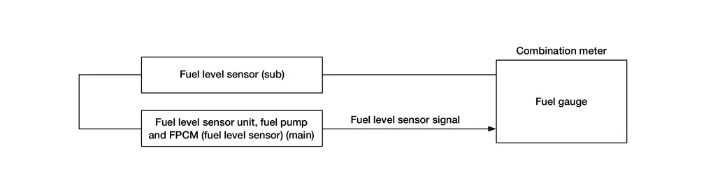
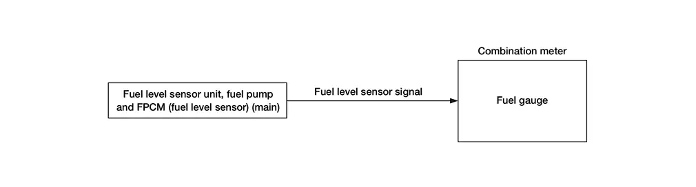
Fuel level sensor (main) and fuel level sensor (sub) transmits the fuel level sensor signal to the combination meter.
|
Fuel level sensor (main)
|
Fuel level sensor unit (sub)
|
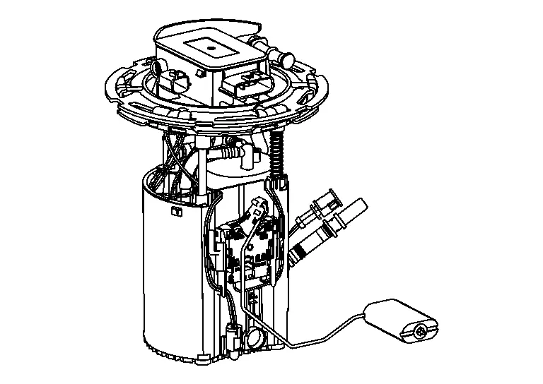
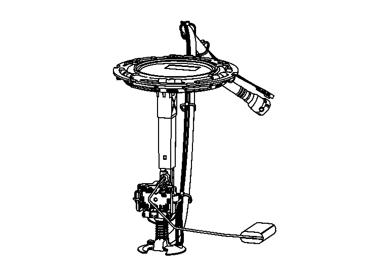
Individual Component Function
-
Fuel level sensor (main)
measures the fuel level in the fuel tank (left side of the Nissan Ariya vehicle) by a float. -
Fuel level sensor unit (sub)
measures the fuel level in the fuel tank (right side of the Nissan Ariya vehicle) by a float.
Component Operation
The fuel level sensor transmits the fuel level sensor signal to the combination meter as the fuel level increases or decreases in the fuel tank.
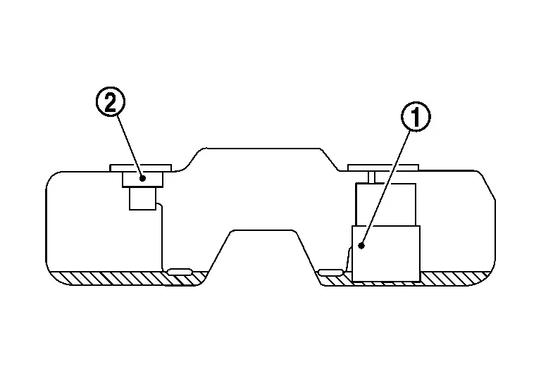
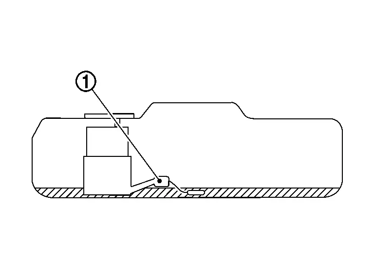
Component Parts Location
Fuel level sensor (main) and fuel level sensor unit (sub) are located in the fuel tank. Refer to Component Parts Location.
Fuel Level Sensor Unit, Fuel Pump and FPCM (Fuel Level Sensor) (Main) - 2WD Models
Component Function Within The System
Fuel level sensor (main) transmits the fuel level sensor signal to the combination meter.
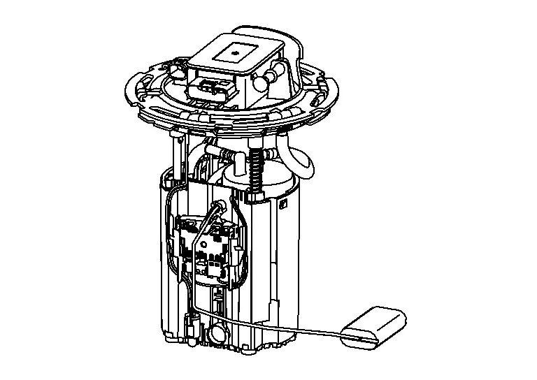
Individual Component Function
Fuel level sensor (main) measures the fuel level in the fuel tank by a float.
Component Operation
The fuel level sensor transmits the fuel level sensor signal to the combination meter as the fuel level increases or decreases in the fuel tank.
Component Parts Location
Fuel level sensor (main) is located in the fuel tank. Refer to Component Parts Location.
Head up Display
Component Parts Location
| No. | Component | Function |
|---|---|---|
| 1. | ADAS (Advanced Driver Assistance System) control unit 2 (with ProPILOT Assist 2.1) | Refer to Component Parts Location (with ProPILOT Assist 2.1) for detailed component location. |
| 2. | ABS (Anti-lock Braking System) actuator and electric unit (control unit) | Refer to Component Parts Location for detailed component location. |
| 3. | ECM (Engine Control Module) | Refer to Component Parts Location for detailed component location. |
| 4. | IPDM E/R (Intelligent Power Distribution Module Engine Room) | Refer to Component Parts Location for detailed component location. |
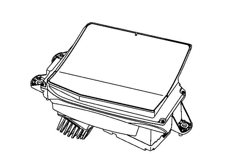
| 5. | Head Up Display unit | Refer to Head Up Display Unit. |
| 6. | 8CH CAN Gateway | Refer to Component Parts Location for detailed component location. |
| 7. | BCM (Body Control Module) | Refer to Component Parts Location for detailed component location. |
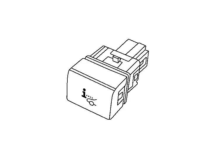
| 8. | Head Up Display switch | Refer to Head Up Display Switch. |
| 9. | Combination meter | Refer to Component Parts Location for detailed component location. |
| 10. | ADAS (Advanced Driver Assistance System) control unit 2 (without ProPILOT Assist 2.1) | Refer to Component Parts Location (without ProPILOT Assist 2.1) for detailed component location. |
| 11. | AV control unit | Refer to Component Parts Location for detailed component location. |
| 12. | Intelligent Key unit | Refer to Component Parts Location for detailed component location. |
Head Up Display Unit
Component Function Within The System
The Head Up Display unit projects various displays on the windshield glass according to signals received from the respective ECUs.
Individual Component Function
-
The image of the TFT liquid crystal display is reflected on the concave mirror, and the image is projected to the windshield glass.
-
Necessary signals are transmitted/received to/from control unit via CAN communication.
Component Operation
Refer to System Description.
Component Parts Location
The Head Up Display unit is installed inside the left side of the instrument panel.
Refer to Component Parts Location.
Head Up Display Switch
Component Function Within The System
Display a Head Up Display by Head Up Display switch operation.
Individual Component Function
Head Up Display switch inputs a switch status to the Head Up Display unit.
Component Operation
-
Adopted momentary switch.
NOTE:
Momentary switch: While push the switch, it becomes ON and returns to an OFF state when release the switch.
-
Change switch operation into ON (0 V) / OFF (5.0 V) of the voltage.
-
Head Up Display unit reads a switch state by an electric potential change.
Component Parts Location
Head Up Display switch is installed in the instrument lower panel LH.
Refer to Component Parts Location.
Other materials:
Multi Remote Ent
CONSULT Function (BCM - MULTI REMOTE ENT)
DATA MONITORNOTE:
The following table includes information (items)
inapplicable to this Nissan Ariya vehicle. For information (items)
applicable to this vehicle, refer to CONSULT display items.
Monitor Item Condition
Stop/start switch
[On/Off] ...
Information Display (combination Meter)
Driving Position Memory
DESIGN/PURPOSEDisplay registration status of driving position. Display pattern Symbol Message
A
Press button
to save driving position
B
Driving position saved
C
Driving position saved
SYSTEM DIAGRAMSIGNAL PATH
The driver sea ...
Espaces de rangement et commoditûˋs du Nissan Rogue. Porte-gobelets ergonomiques
Porte-gobelets ergonomiques
Informations et sûˋcuritûˋ
MISE EN GARDE
Pour ûˋviter tout risque de brû£lure ou de projection de liquide dans l'habitacle du Nissan Rogue, adoptez une conduite souple et ûˋvitez les manéuvres brusques lorsque des boissons sont prûˋsentes dans les supports.
...