Nissan Rogue (T33) 2021-Present Service Manual: System
Headlamp System
System Description
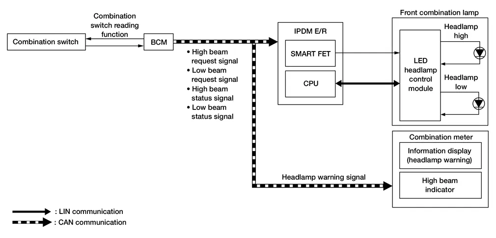
SYSTEM DIAGRAM
| Component | Function | |
|---|---|---|
| Headlamp | Headlamp (HI) |
|
| Headlamp (LO) |
|
|
| LED headlamp control module | Refer to LED Headlamp Control Module. | |
| IPDM E/R |
|
|
| BCM |
|
|
| Combination meter |
|
|
| Combination switch | Lighting and turn signal switch | Transmits each switch condition signal to the BCM. |
OUTLINE
Headlamp is controlled by combination switch reading function and headlamp control function of BCM, and Smart FET control function and LIN communication function of IPDM E/R.
SIGNAL TRANSMISSION FUNCTION LIST
| Signal name | Input | Output | Description |
|---|---|---|---|
| Combination switch signal | Combination switch | BCM | Transmits the combination switch signal to the BCM. |
| High beam request signal | BCM | IPDM E/R (CAN) | Transmits the high beam request signal via CAN communication. |
| Low beam request signal | BCM | IPDM E/R (CAN) | Transmits the low beam request signal via CAN communication. |
| High beam status signal | BCM | Combination meter (CAN) | Transmits the high beam status signal via CAN communication. |
| Low beam status signal | BCM | Combination meter (CAN) | Transmits the low beam status signal via CAN communication. |
| Headlamp warning signal | BCM | Combination meter (CAN) | Transmits the headlamp warning signal via CAN communication. |
HEADLAMP (LO) OPERATION
-
BCM detects the combination switch condition with the combination switch reading function.
-
BCM transmits the low beam request signal to IPDM E/R and low beam status signal to the combination meter via CAN communication according to the headlamp (LO) ON condition.
Headlamp (LO) ON condition (when any of the following conditions are satisfied):
-
Lighting switch 1ST (only when the illumination judgement by auto light function is ON). Refer to System Description (for Canada).
-
Lighting switch 2ND
-
Lighting switch AUTO (only when the illumination judgement by auto light function is ON). Refer to System Description.
-
Lighting switch PASS
-
-
IPDM E/R turns the integrated Smart FET ON according to low beam request signal, and transmits the control signal to LED headlamp control module.
-
IPDM E/R transmits the request to LED headlamp control module (via LIN communication) according to low beam request signal.
-
LED headlamp control module turns the headlamp (LO) ON according to the control signal and request (via LIN communication) from IPDM E/R.
HEADLAMP (HI) OPERATION
-
BCM transmits the high beam request signal to IPDM E/R and high beam status signal to the combination meter via CAN communication according to the headlamp (HI) ON condition.
Headlamp (HI) ON condition (when any of the following conditions are satisfied):
For Canada
-
Lighting switch HI with the lighting switch 1ST or AUTO (only when the illumination judgement by auto light function is ON). Refer to System Description.
-
Lighting switch HI with the lighting switch 2ND
-
High beam assist switch ON with the lighting switch 1ST or AUTO (only when the illumination judgement by auto light function is ON and the illumination judgement by high beam assist system is ON). Refer to System Description.
-
Lighting switch PASS
Except for Canada
-
Lighting switch HI with the lighting switch 2ND
-
Lighting switch HI with the lighting switch AUTO (only when the illumination judgement by auto light function is ON). Refer to System Description.
-
High beam assist switch ON with the lighting switch AUTO (only when the illumination judgement by auto light function is ON and the illumination judgement by high beam assist system is ON). Refer to System Description.
-
Lighting switch PASS
-
-
IPDM E/R turns the integrated Smart FET ON according to high beam request signal, and transmits the control signal to LED headlamp control module.
-
IPDM E/R transmits the request to LED headlamp control module (via LIN communication) according to high beam request signal.
-
LED headlamp control module turns the headlamp (HI) ON according to the control signal and request (via LIN communication) from IPDM E/R.
-
Combination meter turns the high beam indicator ON according to the high beam status signal.
HEADLAMP WARNING OPERATION
Headlamp warning warns the driver that there is a malfunction in LED headlamp system. Refer to Headlamp Warning.
LED HEADLAMP
-
Semiconductor device (Light emitting diode: LED), which is illuminated when forward bias electric voltage is applied, is adopted as the source of light instead of halogen bulb or xenon bulb.
-
Comparing to halogen headlamp or xenon headlamp, LED headlamp is electrically power saving, durable, and is illuminated in the similar color to the sunlight. Bright, natural, and eye-friendly visibility can be obtained.
Precautions for Trouble Diagnosis
Representative malfunction examples are; “Light does not turn ON”, “Light blinks”, and “Brightness is inadequate.” Such malfunctions, however, occasionally by occur LED control module malfunction or lamp case malfunction. Specify the malfunctioning part with diagnosis procedure.
CAUTION:
-
Never touch the harness, LED headlamp control module, the inside and metal part of lamp when turning the headlamp ON or operating the lighting switch, for preventing electrical shock.
-
Never work with wet hands, for preventing electrical shock.
-
Never perform LED headlamp control module circuit diagnosis with a circuit tester or an equivalent.
-
Temporarily install the headlamps on the Nissan Ariya vehicle. Always connect power supply to the connector (vehicle side) when checking ON/OFF status.
-
Disconnect the battery negative terminal before disconnecting the lamp socket connector or the harness connector.
-
Check for blown (open) of the fusible link(s), open around connector, short, disconnection if the symptom is caused by electric error.
-
Always check for deformation or hole of headlamp housing and engagement of bulb cover. Otherwise, water may enter into headlamp because of damage of headlamp housing and contact to LED headlamp control module connector. The normal operation may be inhibited when short circuit to power supply is detected.
 NOTE:
NOTE:
Turn the switch OFF once before turning ON, if the ON/OFF is inoperative.
Intelligent Auto Light System
System Description (With Type A Meter)
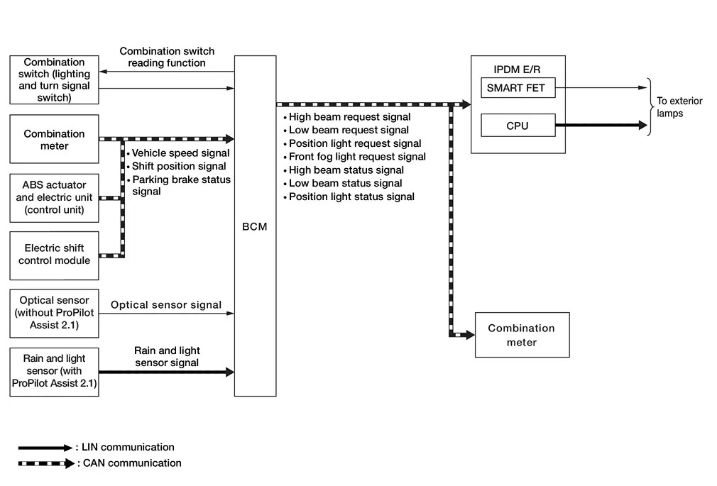
SYSTEM DIAGRAM
| Component | Function | |
|---|---|---|
| Optical sensor | Refer to Optical Sensor. | |
| Rain and light sensor | Refer to Rain and Light Sensor. | |
| IPDM E/R |
|
|
| BCM |
|
|
| Combination meter |
|
|
| ABS actuator and electric unit (control unit) |
|
|
| TCM | TCM transmits the shift position signal to the BCM via CAN communication. | |
| Combination switch | Lighting and turn signal switch | Transmits each switch condition signal to the BCM. |
OUTLINE
-
Intelligent auto light system is controlled by each function of BCM and IPDM E/R.
Control by BCM
-
Combination switch reading function
-
Auto light function
-
Wiper linked auto lighting function
-
Delay timer function
Control by IPDM E/R
-
Smart FET control function
-
LIN communication function
-
-
Intelligent auto light system has the auto light function, wiper linked auto lighting function and delay timer function.
-
Auto light function automatically turns ON/OFF the exterior lamps*, depending on the outside brightness.
-
Wiper linked auto lighting function automatically turns ON/OFF the exterior lamps* when the lighting switch is in the AUTO position, according to a front wiper operation.
-
Delay timer function turns the exterior lamps* OFF depending on the Nissan Ariya vehicle condition with the auto light function when the ignition switch is placed OFF.
-
*: Headlamp (LO/HI), parking lamp, license plate lamp, side marker lamp and tail lamp.
NOTE:
-
Headlamp (HI) depend on the combination switch condition.
SIGNAL TRANSMISSION FUNCTION LIST
| Signal name | Input | Output | Description |
|---|---|---|---|
| Combination switch signal | Combination switch | BCM | Transmits the combination switch signal to the BCM. |
| Nissan Ariya Vehicle speed signal | ABS actuator and electric unit (control unit) | BCM (CAN) | Transmits the Nissan Ariya vehicle speed signal via CAN communication. |
| Shift position signal | TCM | BCM (CAN) | Transmits the shift position signal via CAN communication. |
| Parking brake status signal | ABS actuator and electric unit (control unit) | BCM (CAN) | Transmits the parking brake status signal via CAN communication. |
| Optical sensor signal | Optical sensor | BCM | Transmits the optical sensor signal to the BCM. |
| Light sensor signal | Rain and light sensor | BCM (LIN) | Transmits the light sensor signal via LIN communication. |
| High beam request signal | BCM | IPDM E/R (CAN) | Transmits the high beam request signal via CAN communication. |
| Low beam request signal | BCM | IPDM E/R (CAN) | Transmits the low beam request signal via CAN communication. |
| Position light request signal | BCM | IPDM E/R (CAN) | Transmits the position light request signal via CAN communication. |
| High beam status signal | BCM | Combinaiton meter (CAN) | Transmits the high beam status signal via CAN communication. |
| Low beam status signal | BCM | Combination meter (CAN) | Transmits the low beam status signal via CAN communication. |
| Position light status signal | BCM | Combination meter (CAN) | Transmits the position light status signal via CAN communication. |
AUTO LIGHT FUNCTION
-
BCM detects the combination switch condition with the combination switch reading function.
-
BCM detects the Nissan Ariya vehicle condition that is required for auto light control with the following signals:
-
Parking brake status signal (received from combination meter via CAN communication)
-
Nissan Ariya Vehicle speed signal [received from ABS actuator and electric unit (control unit) via CAN communication]
-
Shift position signal (received from TCM via CAN communication)
-
-
BCM supplies voltage to the optical sensor when the ignition switch is placed ON (without ProPILOT assist 2.1).
-
Optical sensor converts outside brightness (lux) to voltage and transmits the optical sensor signal to BCM (without ProPILOT assist 2.1).
-
Rain and light sensor converts outside brightness to a signal and transmits the light sensor signal to BCM via LIN communication (with ProPILOT assist 2.1).
-
When ignition switch is placed ON, the BCM detects outside brightness from the optical sensor signal and judges ON/OFF condition of each exterior lamp, depending on the outside brightness condition (without ProPILOT assist 2.1).
-
When ignition switch is placed ON, the BCM detects outside brightness from the light sensor signal and judges ON/OFF condition of each exterior lamp, depending on the outside brightness condition (with ProPILOT assist 2.1).
-
BCM transmits each request signal to IPDM E/R and each status signal to combination meter via CAN communication, according to ON/OFF condition by the auto light function.
Lighting conditions for lighting switch AUTO (when all of the following conditions are satisfied):
-
Ignition switch ON
-
Parking brake is released or Nissan Ariya vehicle speed is 2.5 MPH (4 km/h) or more
-
Lighting judgment ON depending on the brightness outside of Nissan Ariya vehicle
Lighting off conditions for lighting switch AUTO (when any of the following conditions are satisfied):
-
Ignition switch OFF
-
Nissan Ariya Vehicle speed is 1.8 MPH (3 km/h) or less and parking brake is operated*
*: Only before releasing the parking brake. After releasing the parking brake, it will not turn lights OFF if the parking brake is operate again.
-
Lighting judgment OFF depending on the brightness outside of Nissan Ariya vehicle
Headlamp lighting conditions when the lighting switch is 1ST (when all of the following conditions are satisfied):
-
Ignition switch ON
-
Nissan Ariya Vehicle speed is 2.5 MPH (4 km/h) or more, or parking brake is released and other than shift selector P range
-
Lighting judgment ON depending on the brightness outside of Nissan Ariya vehicle
Headlamp lighting OFF conditions when the lighting switch is 1ST (when any of the following conditions are satisfied):
-
Ignition switch OFF
-
Nissan Ariya Vehicle speed is 1.8 MPH (3 km/h) or less and parking brake is operated
-
Vehicle speed is 1.8 MPH (3 km/h) or less and shift selector is P range
-
Lighting judgment OFF depending on the brightness outside of Nissan Ariya vehicle
-
NOTE:
If the optical sensor signal (without ProPILOT Assist 2.1) or light sensor signal (with ProPILOT Assist 2.1) is missing, the BCM turns the headlamp (LO) ON and turns high beam assist OFF.
WIPER LINKED AUTO LIGHTING FUNCTION
BCM turns each exterior lamp ON when the within 60 seconds detecting 4 operations of the front wiper while the lighting switch is in AUTO position.
NOTE:
BCM turns OFF the headlamps 3 seconds after the front wiper switch is turned OFF.
DELAY TIMER FUNCTION
BCM turns the exterior lamps OFF depending on the vehicle condition with the auto light function when the ignition switch is placed OFF.
-
Turns the exterior lamps OFF 30 seconds after the ignition switch is placed OFF.
-
Delay timer function turns OFF, when the engine running or the lighting switch is other than AUTO.
NOTE:
When any position other than the lighting switch AUTO is set, the auto light function switches to the exterior lamp battery saver function.
System Description (With Type B Meter)
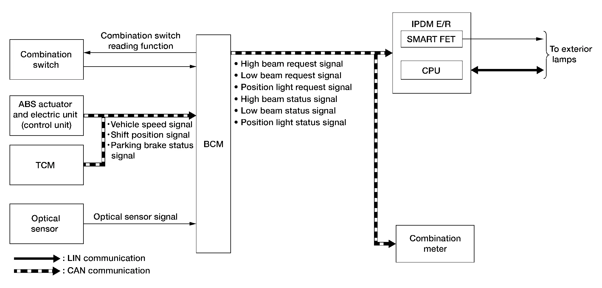
SYSTEM DIAGRAM
| Component | Function | |
|---|---|---|
| Optical sensor | Refer to Optical Sensor. | |
| IPDM E/R |
|
|
| BCM |
|
|
| Combination meter |
|
|
| ABS actuator and electric unit (control unit) |
|
|
| TCM | TCM transmits the shift position signal to the BCM via CAN communication. | |
| Combination switch | Lighting and turn signal switch | Transmits each switch condition signal to the BCM. |
OUTLINE
-
Intelligent auto light system is controlled by each function of BCM and IPDM E/R.
Control by BCM
-
Combination switch reading function
-
Auto light function
-
Wiper linked auto lighting function
-
Delay timer function
Control by IPDM E/R
-
Smart FET control function
-
LIN communication function
-
-
Intelligent auto light system has the auto light function, wiper linked auto lighting function and delay timer function.
-
Auto light function automatically turns ON/OFF the exterior lamps*, depending on the outside brightness.
-
Wiper linked auto lighting function automatically turns ON/OFF the exterior lamps* when the lighting switch is in the AUTO position, according to a front wiper operation.
-
Delay timer function turns the exterior lamps* OFF depending on the Nissan Ariya vehicle condition with the auto light function when the ignition switch is placed OFF.
-
*: Headlamp (LO/HI), parking lamp, license plate lamp, side marker lamp and tail lamp.
NOTE:
-
Headlamp (HI) depend on the combination switch condition.
SIGNAL TRANSMISSION FUNCTION LIST
| Signal name | Input | Output | Description |
|---|---|---|---|
| Combination switch signal | Combination switch | BCM | Transmits the combination switch signal to the BCM. |
| Nissan Ariya Vehicle speed signal | ABS actuator and electric unit (control unit) | BCM (CAN) | Transmits the Nissan Ariya vehicle speed signal via CAN communication. |
| Shift position signal | TCM | BCM (CAN) | Transmits the shift position signal via CAN communication. |
| Parking brake status signal | ABS actuator and electric unit (control unit) | BCM (CAN) | Transmits the parking brake status signal via CAN communication. |
| Optical sensor signal | Optical sensor | BCM | Transmits the optical sensor signal to the BCM. |
| High beam request signal | BCM | IPDM E/R (CAN) | Transmits the high beam request signal via CAN communication. |
| Low beam request signal | BCM | IPDM E/R (CAN) | Transmits the low beam request signal via CAN communication. |
| Position light request signal | BCM | IPDM E/R (CAN) | Transmits the position light request signal via CAN communication. |
| High beam status signal | BCM | Combinaiton meter (CAN) | Transmits the high beam status signal via CAN communication. |
| Low beam status signal | BCM | Combination meter (CAN) | Transmits the low beam status signal via CAN communication. |
| Position light status signal | BCM | Combination meter (CAN) | Transmits the position light status signal via CAN communication. |
AUTO LIGHT FUNCTION
-
BCM detects the combination switch condition with the combination switch reading function.
-
BCM detects the Nissan Ariya vehicle condition that is required for auto light control with the following signals:
-
Parking brake status signal (received from combination meter via CAN communication)
-
Nissan Ariya Vehicle speed signal [received from ABS actuator and electric unit (control unit) via CAN communication]
-
Shift position signal (received from TCM via CAN communication)
-
-
BCM supplies voltage to the optical sensor when the ignition switch is placed ON.
-
Optical sensor converts outside brightness (lux) to voltage and transmits the optical sensor signal to BCM.
-
When ignition switch is placed ON, BCM detects outside brightness from the optical sensor signal and judges ON/OFF condition of each exterior lamp, depending on the outside brightness condition.
-
BCM transmits each request signal to IPDM E/R and each status signal to combination meter via CAN communication, according to ON/OFF condition by the auto light function.
Lighting conditions for lighting switch AUTO (when all of the following conditions are satisfied):
-
Ignition switch ON
-
Parking brake is released or Nissan Ariya vehicle speed is 2.5 MPH (4 km/h) or more
-
Lighting judgment ON depending on the brightness outside of Nissan Ariya vehicle
Lighting off conditions for lighting switch AUTO (when any of the following conditions are satisfied):
-
Ignition switch OFF
-
Nissan Ariya Vehicle speed is 1.8 MPH (3 km/h) or less and parking brake is operated*
*: Only before releasing the parking brake. After releasing the parking brake, it will not turn lights OFF if the parking brake is operate again.
-
Lighting judgment OFF depending on the brightness outside of Nissan Ariya vehicle
Headlamp lighting conditions when the lighting switch is 1ST (when all of the following conditions are satisfied):
-
Ignition switch ON
-
Nissan Ariya Vehicle speed is 2.5 MPH (4 km/h) or more, or parking brake is released and other than shift selector P range
-
Lighting judgment ON depending on the brightness outside of Nissan Ariya vehicle
Headlamp lighting OFF conditions when the lighting switch is 1ST (when any of the following conditions are satisfied):
-
Ignition switch OFF
-
Nissan Ariya Vehicle speed is 1.8 MPH (3 km/h) or less and parking brake is operated
-
Vehicle speed is 1.8 MPH (3 km/h) or less and shift selector is P range
-
Lighting judgment OFF depending on the brightness outside of Nissan Ariya vehicle
-
NOTE:
If the optical sensor signal is missing, the BCM turns the headlamp (LO) ON and turns high beam assist OFF.
WIPER LINKED AUTO LIGHTING FUNCTION
BCM turns each exterior lamp ON when the within 60 seconds detecting 4 operations of the front wiper while the lighting switch is in AUTO position.
NOTE:
BCM turns OFF the headlamps 3 seconds after the front wiper switch is turned OFF.
DELAY TIMER FUNCTION
BCM turns the exterior lamps OFF depending on the vehicle condition with the auto light function when the ignition switch is placed OFF.
-
Turns the exterior lamps OFF 30 seconds after the ignition switch is placed OFF.
-
Delay timer function turns OFF, when the engine running or the lighting switch is other than AUTO.
NOTE:
When any position other than the lighting switch AUTO is set, the auto light function switches to the exterior lamp battery saver function.
High Beam Assist System
System Description
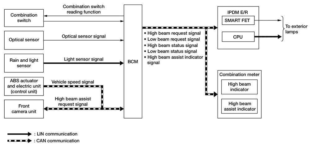
SYSTEM DIAGRAM
| Component | Function | |
|---|---|---|
| Optical sensor | Refer to Optical Sensor. | |
| Rain and light sensor | Refer to Rain and Light Sensor. | |
| Front camera unit | Judges the Nissan Ariya vehicle status from each signal in order to control high beam assist control. | |
| IPDM E/R | Transmits the control signal and request (via LIN communication) to the load according to the request from the BCM via CAN communication. | |
| BCM |
|
|
| Combination meter | Turns the indicators ON/OFF according to the status signal from the BCM via CAN communication. | |
| ABS actuator and electric unit (control unit) | ABS actuator and electric unit (control unit) transmits the Nissan Ariya vehicle speed signal to the front camera unit via CAN communication. | |
| Combination switch | Lighting and turn signal switch | Transmits each switch condition signal to the BCM. |
OUTLINE
-
High beam assist system is a system that can reduce the driver's switch operation load. The system automatically switches the headlamp to the low beam mode when a Nissan Ariya vehicle ahead or an oncoming vehicle appears, while driving the vehicle with the headlamps in high beam mode at night.
-
When the high beam assist system operation permission conditions are satisfied, the high beam assist indicator in the combination meter turns ON and informs that high beam assist is in operation.
-
High beam assist system is controlled by each function of BCM, IPDM E/R and front camera unit.
Control by BCM
-
Combination switch reading function
-
Auto light function
-
High beam assist control function
-
Headlamp control function
Control by IPDM E/R
-
Smart FET control function
-
LIN communication function
Control by front camera unit
-
High beam assist control function
-
SIGNAL TRANSMISSION FUNCTION LIST
| Signal name | Input | Output | Description |
|---|---|---|---|
| Combination switch signal | Combination switch | BCM | Transmits the combination switch signal to the BCM. |
| Optical sensor signal | Optical sensor | BCM | Transmits the optical sensor signal to the BCM. |
| Light sensor signal | Rain and light sensor | BCM (LIN) | Transmits the light sensor signal via LIN communication. |
| Nissan Ariya Vehicle speed signal | ABS actuator and electric unit (control unit) | Front camera unit (CAN) | Transmits the Nissan Ariya vehicle speed signal via CAN communication. |
| High beam assist request signal | Front camera unit | BCM (CAN) | Transmits the high beam assist request signal via CAN communication. |
| High beam request signal | BCM | IPDM E/R (CAN) | Transmits the high beam request signal via CAN communication. |
| Low beam request signal | BCM | IPDM E/R (CAN) | Transmits the low beam request signal via CAN communication. |
| High beam status signal | BCM | Combination meter (CAN) | Transmits the high beam status signal via CAN communication. |
| Low beam status signal | BCM | Combination meter (CAN) | Transmits the low beam status signal via CAN communication. |
| High beam assist indicator signal | BCM | Combination meter (CAN) | Transmits the high beam assist indicator signal via CAN communication. |
OPERATION DESCRIPTION
-
BCM detects the combination switch condition with the combination switch reading function.
-
BCM transmits the high beam assist indicator signal to the combination meter via CAN communication when the high beam assist system operation permission conditions are satisfied.
High beam assist system operation permission conditions (when all of following conditions are satisfied):
-
Ignition switch ON
-
Lighting switch AUTO (only when the illuminating judgement by auto light function is ON). Refer to System Description (except for Canada).
-
Lighting switch AUTO or 1ST (only when the illuminating judgement by auto light function is ON). Refer to System Description (for Canada).
-
High beam assist switch ON
-
-
Combination meter turns the high beam assist indicator ON according to the high beam assist indicator signal.
-
Front camera unit detects the Nissan Ariya vehicle status and ambient status that are required for high beam assist control with the following signals:
-
Nissan Ariya Vehicle speed signal [received from ABS actuator and electric unit (control unit) via CAN communication]
-
Ambient light signal (detected from front camera unit)
-
Image sensor signal (detected from front camera unit)
-
-
Front camera unit judges the current recommended beam according to the Nissan Ariya vehicle status and ambient condition, and transmits the high beam assist request signal (headlamp HI operation / headlamp LO operation) to BCM via CAN communication.
-
BCM switches the headlamp LO operation / headlamp HI operation according to high beam assist request signal while the high beam assist system operation permission conditions are satisfied. For headlamp operation, refer to System Description.
NOTE:
If the optical sensor signal (without ProPILOT Assist 2.1) or light sensor signal (with ProPILOT Assist 2.1) is missing, the BCM turns the headlamp (LO) ON and turns high beam assist OFF.
RECOMMENDED BEAM JUDGEMENT BY FRONT CAMERA UNIT
Headlamp HI Operation Request
Front camera unit requests the headlamp HI operation to BCM when all of following conditions are satisfied:
-
Detects the vehicle speed is approx. 19 MPH (30 km/h) or more.
-
Recognizes the ambient condition is dark.
-
Recognizes there is no oncoming Nissan Ariya vehicle or no vehicle ahead in front of the vehicle.
Headlamp LO Operation Request
Front camera unit requests the headlamp LO operation to BCM when either of following conditions is satisfied:
-
Detects the vehicle speed is approx. 13 MPH (20 km/h) or less.
-
Recognizes the ambient condition is bright.
-
Recognizes there is oncoming Nissan Ariya vehicle or vehicle ahead in front of the vehicle.
Daytime Running Light System
System Description
SYSTEM DIAGRAM
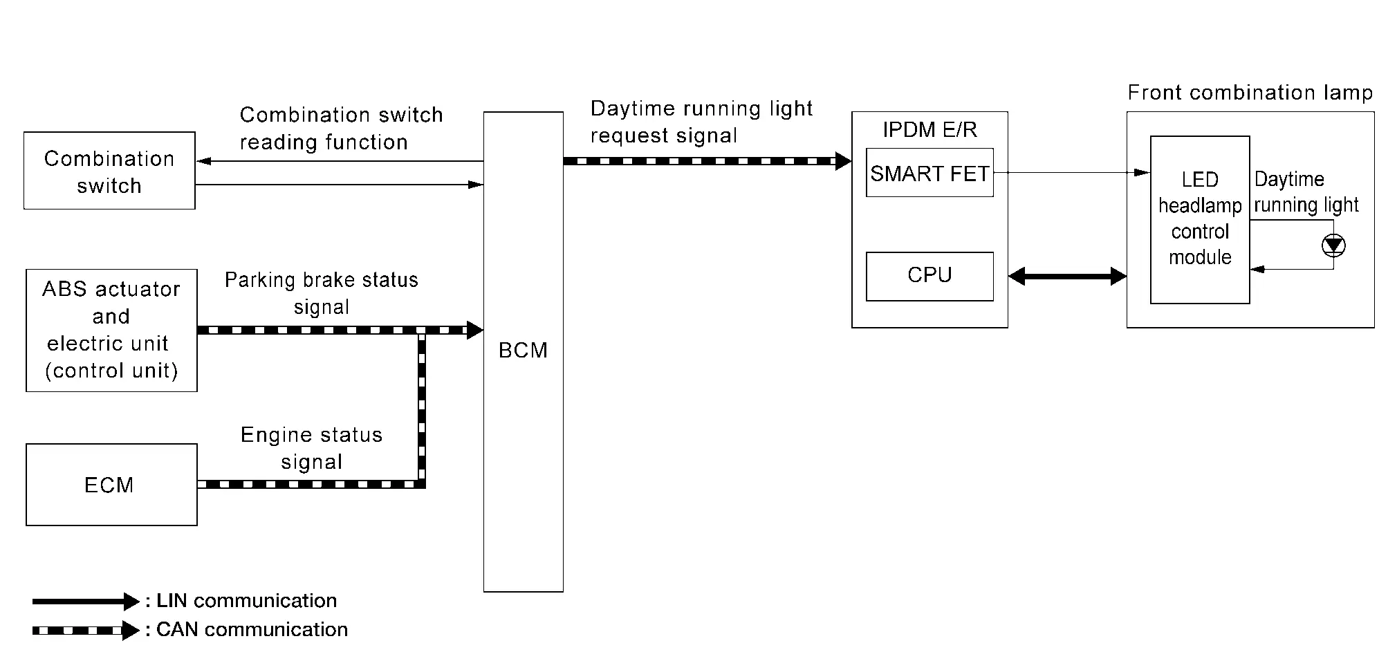
| Component | Function | |
|---|---|---|
| Front combination lamp | Daytime running light |
|
| LED headlamp control module | Refer to LED Headlamp Control Module. | |
| IPDM E/R | Transmits the control signal and request (via LIN communication) to the LED headlamp control module according to the request from the BCM via CAN communication. | |
| BCM |
|
|
| ECM | ECM transmits the engine status signal to the BCM via CAN communication. | |
| ABS actuator and electric unit (control unit) | ABS actuator and electric unit (control unit) transmits the parking brake status signal to the BCM via CAN communication. | |
| Combination switch | Lighting and turn signal switch | Transmits each switch condition signal to the BCM. |
OUTLINE
Daytime running light is controlled by daytime running light control function and combination switch reading function of BCM, and Smart FET control function and LIN communication function of IPDM E/R.
SIGNAL TRANSMISSION FUNCTION LIST
| Signal name | Input | Output | Description |
|---|---|---|---|
| Combination switch signal | Combination switch | BCM | Transmits the combination switch signal to the BCM. |
| Parking brake status signal | ABS actuator and electric unit (control unit) | BCM (CAN) | Transmits the parking brake status signal via CAN communication. |
| Engine status signal | ECM | BCM (CAN) | Transmits the engine status signal via CAN communication. |
| Daytime running light request signal | BCM | IPDM E/R (CAN) | Transmits the daytime running light request signal via CAN communication. |
DAYTIME RUNNING LIGHT OPERATION
-
BCM detects the combination switch condition by the combination switch reading function.
-
BCM detects Nissan Ariya vehicle condition depending on the engine status signal and parking brake status signal (received from ECM and combination meter via CAN communication).
-
BCM transmits the daytime running light request signal to IPDM E/R via CAN communication according to the daytime running light ON condition.
Daytime running light ON condition
-
Engine running, parking brake release and any following conditions are satisfied:
Except Canada
-
Lighting switch OFF
-
Lighting switch 1ST
-
Lighting switch AUTO (only when the illumination judgement by auto light function is OFF). Refer to System Description.
For Canada
-
Lighting switch 1ST (only when the illumination judgement by auto light function is OFF). Refer to System Description.
-
Lighting switch AUTO (only when the illumination judgement by auto light function is OFF). Refer to System Description.
-
-
-
IPDM E/R turns the integrated Smart FET ON according to daytime running light request signal, and transmits the control signal to LED headlamp control module.
-
IPDM E/R transmits the request to LED headlamp control module (via LIN communication) according to daytime running light request signal.
-
LED headlamp control module turns the daytime running light ON according to the control signal and request (via LIN communication) from IPDM E/R.
NOTE:
Daytime running light and parking lamp use a common light source. When the daytime running light is turned ON while parking lamp is ON, the parking lamp/daytime running light is brightening.
Turn Signal and Hazard Warning Lamp System
System Description
SYSTEM DIAGRAM
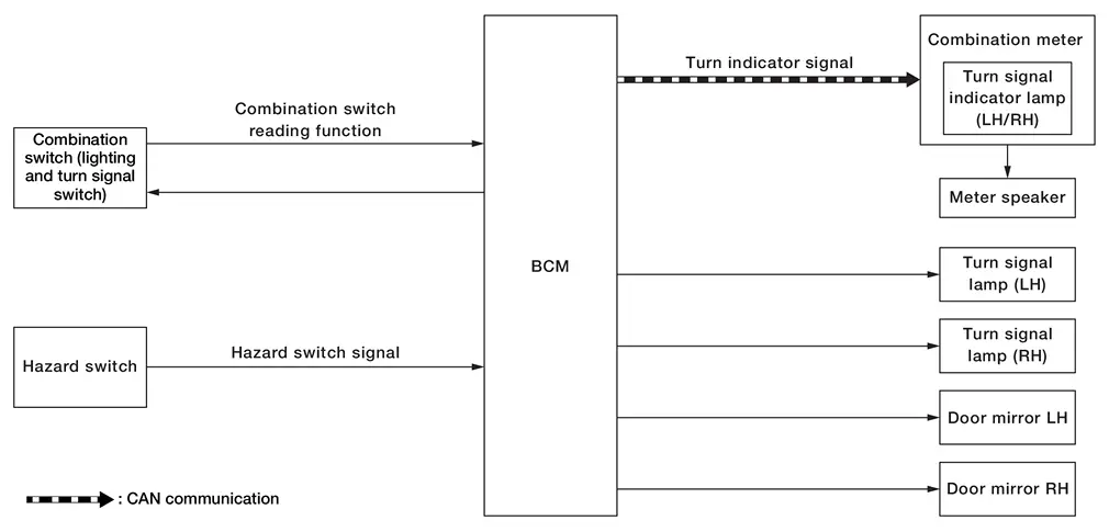
| Component | Function | |
|---|---|---|
| Front combination lamp | Front turn signal lamp |
|
| Door mirror | Side turn signal lamp |
|
| Rear combination lamp (body side) | Rear turn signal lamp |
|
| Hazard switch | Refer to Hazard Switch. | |
| BCM |
|
|
| Combination meter | Blinks the turn signal indicator and outputs the turn signal operating sound to the meter speaker according to the status signal from the BCM via CAN communication. | |
| Meter speaker | Outputs the turn signal operating sound according to the signal from the combination meter. | |
| Combination switch | Lighting and turn signal switch | Transmits each switch condition signal to the BCM. |
OUTLINE
Turn signal lamp and hazard warning lamp is controlled by combination switch reading function and the flasher control function of BCM.
SIGNAL TRANSMISSION FUNCTION LIST
| Signal name | Input | Output | Description |
|---|---|---|---|
| Combination switch signal | Combination switch | BCM | Transmits the combination switch signal to the BCM. |
| Hazard switch signal | Hazard switch | BCM | Transmits the hazard switch signal to the BCM. |
| Car crash information signal | Air bag diagnosis sensor unit | BCM (CAN) | Transmits the car crash information signal via CAN communication. |
| Turn indicator signal | BCM | Combinaiton meter (CAN) | Transmits the turn indicator signal via CAN communication. |
TURN SIGNAL LAMP OPERATION
-
BCM detects the combination switch condition by the combination switch reading function.
-
BCM supplies voltage to the left or right turn signal lamp circuit when the ignition switch is ON and the turn signal switch is in the left or right position. BCM blinks the turn signal lamp.
HAZARD WARNING LAMP OPERATION
BCM supplies voltage to both turn signal lamp circuits when the hazard switch is ON. BCM blinks the hazard warning lamp.
TURN SIGNAL INDICATOR AND TURN SIGNAL SOUND OPERATION
-
BCM transmits the turn indicator signal to the combination meter via CAN communication while the turn signal lamp and the hazard warning lamp are operating.
-
Combination meter outputs the turn signal sound to the meter speaker while blinking the turn signal indicator according to the turn indicator signal.
-
Meter speaker outputs the turn signal sound according to the signal from combination meter.
3-TIME FLASHER FUNCTION
-
By a short touch of the turn signal lever, BCM blinks the turn signal lamps 3 times in the selected direction.
-
Cancels the operation when short touch of the turn signal lever in the reverse direction during the 3-time flasher function operation.
HIGH FLASHER OPERATION
-
BCM detects the turn signal lamp circuit status from the current value.
-
BCM increases the turn signal lamp blinking speed if the lamp or harness open is detected with the turn signal lamp operating.
NOTE:
The blinking speed is normal while operating the hazard warning lamp.
AUTO HAZARD FUNCTION
-
The air bag diagnosis sensor unit transmits a car crash information signal to the BCM via CAN communication, when the air bag diagnosis sensor unit detects strong impact to the Nissan Ariya vehicle body while ignition switch is ON.
-
When a car crash information signal from the air bag diagnosis sensor unit is detected, the BCM supplies voltage to each turn signal lamp system and the hazard lamp blinks.
Parking, License Plate, Side Marker and Tail Lamp System
System Description
SYSTEM DIAGRAM
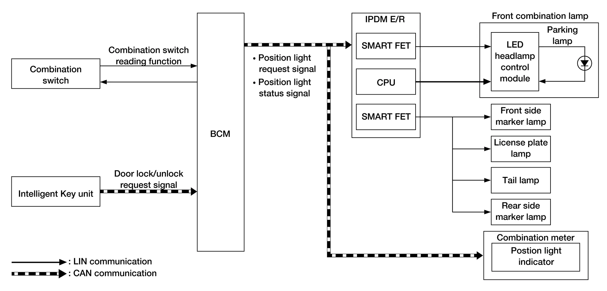
| Component | Function | |
|---|---|---|
| Front combination lamp | Parking lamp |
|
| Front side marker lamp |
|
|
| LED headlamp control module | Refer to LED Headlamp Control Module. | |
| Rear combination lamp (body side) | Tail lamp |
|
| Rear side marker lamp |
|
|
| Rear combination lamp (back door side) | Tail lamp |
|
| License plate lamp |
|
|
| IPDM E/R |
|
|
| BCM |
|
|
| Combination meter | Turns the position light indicator ON/OFF according to the status signal from the BCM via CAN communication. | |
| Intelligent Key unit | Transmits the door lock/unlock request signal to the BCM via CAN communication from door lock/unlock button operation. | |
| Combination switch | Lighting and turn signal switch | Transmits each switch condition signal to the BCM. |
OUTLINE
Parking, license plate, side marker and tail lamps are controlled by combination switch reading function and parking, license plate, side marker and tail lamps control function of BCM, and Smart FET control function and LIN communication function of IPDM E/R.
SIGNAL TRANSMISSION FUNCTION LIST
| Signal name | Input | Output | Description |
|---|---|---|---|
| Combination switch signal | Combination switch | BCM | Transmits the combination switch signal to the BCM. |
| Door lock/unlock request signal | Intelligent Key unit | BCM (CAN) | Transmits the door lock/unlock signal via CAN communication. |
| Position light request signal | BCM | IPDM E/R (CAN) | Transmits the position light request signal via CAN communication. |
| Position light status signal | BCM | Combinaiton meter (CAN) | Transmits the position light status signal via CAN communication. |
PARKING, LICENSE PLATE, SIDE MARKER AND TAIL LAMP OPERATION
-
BCM detects the combination switch condition by the combination switch reading function.
-
BCM transmits the position light request signal to IPDM E/R and position light status signal to the combination meter via CAN communication according to the parking, license plate, side marker and tail lamps ON condition.
Parking, license plate, side marker and tail lamps ON condition (when any of the following conditions are satisfied):
-
Lighting switch 1ST
-
Lighting switch 2ND
-
Lighting switch AUTO (only when the illumination judgement by auto light function is ON). Refer to System Description.
-
-
IPDM E/R turns the integrated Smart FET ON and turns the parking, license plate, side marker and tail lamps ON according to the position light request signal.
-
IPDM E/R turns the integrated Smart FET ON according to position light request signal, and transmits the control signal to LED headlamp control module.
-
IPDM E/R transmits the request to LED headlamp control module (via LIN communication) according to position light request signal.
-
LED headlamp control module turns the parking lamp ON according to the control signal and request (via LIN communication) from IPDM E/R.
-
Combination meter turns the position light indicator ON according to the position light status signal.
NOTE:
When headlamp is turned ON while the parking, license plate, side marker and tail lamps are ON the position light indicator turns OFF (with type A meter).
SIGNATURE LIGHT FUNCTION
Description
The signature light function is a function that turns ON the parking lamp, license plate lamp, side marker lamp and tail lamp for a set period of time when the doors are locked or unlocked from outside the Nissan Ariya vehicle.
Operation Description
BCM transmits the position light request signal to IPDM E/R and position light status signal to the combination meter via CAN communication according to the signature light function ON condition.
Signature light function ON condition (operation when doors are unlocked)
-
When all of the following conditions are satisfied, the signature light function operates when door unlock operation is performed from outside the Nissan Ariya vehicle (Intelligent Key, door request switch, etc.):
-
Ignition switch: OFF
-
Door open/close status: All door close
-
Door lock status: All door lock
-
-
When any of the following conditions is satisfied while the signature light function is operating, the signature light function stops:
-
Ignition switch: ON
-
Since signature light function ON, approx. 30 seconds are passed.
NOTE:
When door lock operation is performed with the Intelligent Key or door request switch, the system changes to operation when doors are locked
-
Signature light function ON condition (operation when doors are locked)
-
When all of the following conditions are satisfied, the signature light function operates when door lock operation is performed from outside the Nissan Ariya vehicle (Intelligent Key or door request switch, etc.):
-
Ignition switch: OFF
-
Door open/close status: All door close
-
-
When any of the following conditions is satisfied while the signature light function is operating, the signature light function stops:
-
Ignition switch: ON
-
Since signature light function ON, approx. 15 seconds are passed.
NOTE:
When door unlock operation is performed with the Intelligent Key or door request switch, the system changes to operation when doors are unlocked.
-
Stop Lamp System
System Description (With ProPILOT Assist 2.1)
SYSTEM DIAGRAM
| Component | Function | |
|---|---|---|
| Rear combination lamp (body side) | Stop lamp |
|
| High-mounted stop lamp |
|
|
| Stop lamp switch | Refer to Stop Lamp Switch. | |
| BCM | Judges the Nissan Ariya vehicle status from each signal, and turns the stop lamp and high-mounted stop lamp ON. | |
| Chassis control module | When the AEB function operates, the chassis control module turns ON the stop lamp relay to turn ON the stop lamps. | |
| Stop lamp relay | Turns ON/OFF based on the control from the chassis control module and turns ON the stop lamps. | |
OUTLINE
Stop lamp and high-mounted stop lamp is controlled by stop lamp switch reading function and the stop lamp and high-mounted stop lamp control function of BCM, automatic emergency braking function of ADAS control unit 2.
SIGNAL TRANSMISSION FUNCTION LIST
| Signal name | Input | Output | Description |
|---|---|---|---|
| Stop lamp switch signal | Stop lamp switch | BCM | Transmits the stop lamp switch signal to the BCM. |
STOP LAMP AND HIGH-MOUNTED STOP LAMP OPERATION
-
BCM detects the brake pedal position status from stop lamp switch.
-
BCM supplies voltage to stop lamp and high-mounted stop lamp according to the stop lamp and high-mounted stop lamp ON condition.
Stop lamp and high-mounted stop lamp ON condition
-
Brake pedal is depressed
-
AUTOMATIC EMERGENCY BRAKING FUNCTION
-
When AEB (Automatic Emergency Braking) operates, the chassis control module turns ON the stop lamp relay. For details about AEB, refer to System Description.
-
When the stop lamp relay is turned ON, the stop lamp and high-mounted stop lamp turn ON.
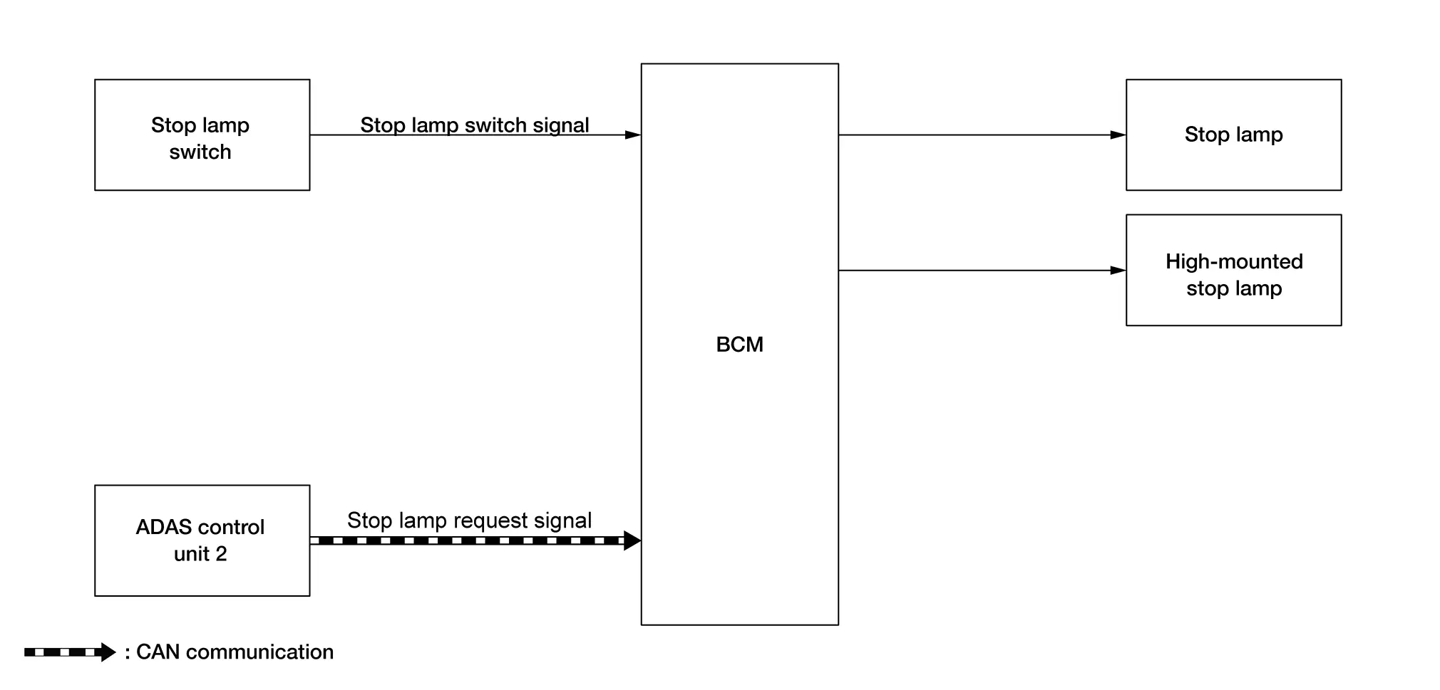
System Description (Without ProPILOT Assist 2.1)
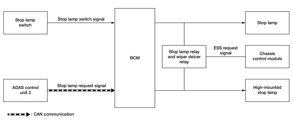
SYSTEM DIAGRAM
| Component | Function | |
|---|---|---|
| Rear combination lamp (body side) | Stop lamp |
|
| High-mounted stop lamp |
|
|
| Stop lamp switch | Refer to Stop Lamp Switch. | |
| BCM | Judges the Nissan Ariya vehicle status from each signal, and turns the stop lamp and high-mounted stop lamp ON. | |
| ADAS control unit 2 | When the AEB function operates, a request is transmitted to the BCM via CAN communication to turn ON the stop lamps. | |
OUTLINE
Stop lamp and high-mounted stop lamp is controlled by stop lamp switch reading function and the stop lamp and high-mounted stop lamp control function of BCM, automatic emergency braking function of ADAS control unit 2.
SIGNAL TRANSMISSION FUNCTION LIST
| Signal name | Input | Output | Description |
|---|---|---|---|
| Stop lamp switch signal | Stop lamp switch | BCM | Transmits the stop lamp switch signal to the BCM. |
| Stop lamp request signal | ADAS control unit 2 | BCM (CAN) | Transmits the stop lamp request signal via CAN communication. |
STOP LAMP AND HIGH-MOUNTED STOP LAMP OPERATION
-
BCM detects the brake pedal position status from stop lamp switch.
-
BCM supplies voltage to stop lamp and high-mounted stop lamp according to the stop lamp and high-mounted stop lamp ON condition.
Stop lamp and high-mounted stop lamp ON condition
-
Brake pedal is depressed
-
AUTOMATIC EMERGENCY BRAKING FUNCTION
-
When AEB (Automatic Emergency Braking) operates, the ADAS control unit 2 transmits the stop lamp request signal to the BCM via CAN communication. For details about AEB, refer to System Description.
-
When the BCM receives the stop lamp request signal from the ADAS control unit 2, it supplies power supply to the stop lamp and high-mounted stop lamps, turning ON the stop lamp and high-mounted stop lamp.
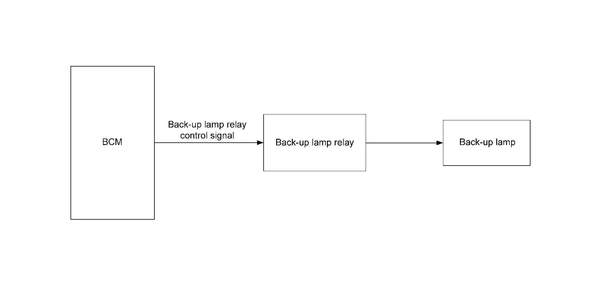
Back-Up Lamp System
System Description
SYSTEM DIAGRAM
| Component | Function | |
|---|---|---|
| Rear combination lamp (back door side) | Back-up lamp |
|
| Back-up lamp relay | Supplies voltage to the back-up lamp with the control from the BCM. | |
| BCM | Controls the back-up lamp relay. | |
OUTLINE
Back-up lamp is controlled by back-up lamp control function of BCM.
BACK-UP LAMP OPERATION
-
BCM turns the back-up lamp relay ON, and turns the back-up lamp ON according to the back-up lamp ON conditions are satisfied.
Back-up lamp ON condition (when all of the following conditions are satisfied):
-
Engine running
-
Shift selector R range
-
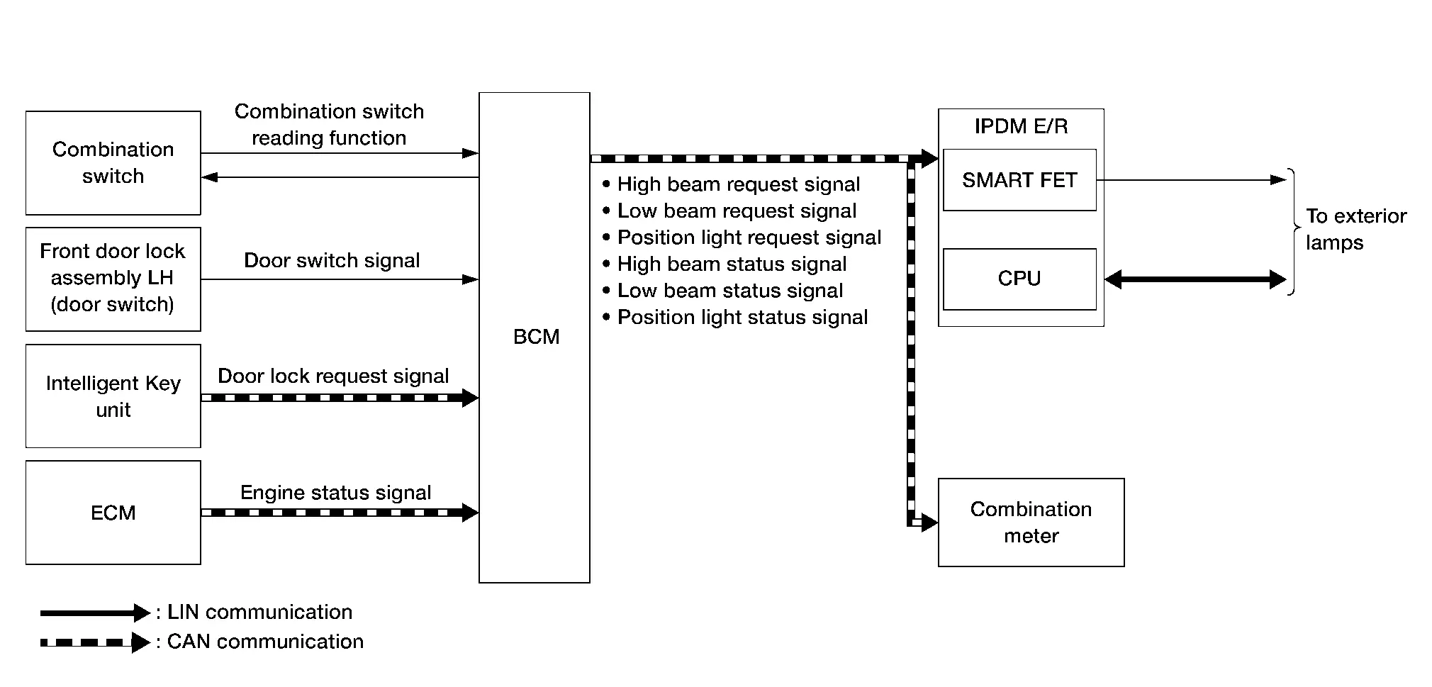
Exterior Lamp Battery Saver System
System Description
SYSTEM DIAGRAM
| Component | Function | |
|---|---|---|
| IPDM E/R |
|
|
| BCM |
|
|
| Combination meter | Turns the indicators ON/OFF or displays the indicator according to the status from the BCM via CAN communication. | |
| Front door lock assembly LH (door switch) | Detects the front door LH condition (open or close), and transmits the door switch signal to the BCM. | |
| Intelligent Key unit | Transmits the door lock request signal to the BCM via CAN communication from door lock button operation. | |
| ECM | ECM transmits the engine status signal to the BCM via CAN communication. | |
| Combination switch | Lighting and turn signal switch | Transmits each switch condition signal to the BCM. |
OUTLINE
-
Exterior lamp battery saver system is controlled by combination switch reading function and exterior lamp battery saver function of BCM, and Smart FET control function of IPDM E/R.
-
BCM turns the exterior lamp* OFF, according to the Nissan Ariya vehicle status when ignition switch is placed OFF while exterior lamp is ON, for preventing battery discharge.
*: Headlamp (LO/HI), parking lamp, license plate lamp, side marker lamp and tail lamp
SIGNAL TRANSMISSION FUNCTION LIST
| Signal name | Input | Output | Description |
|---|---|---|---|
| Combination switch signal | Combination switch | BCM | Transmits the combination switch signal to the BCM. |
| Door switch signal | Front door lock assembly LH (door switch) | BCM | Transmits the door switch signal to the BCM. |
| Door lock request signal | Intelligent Key unit | BCM (CAN) | Transmits the door lock request signal via CAN communication. |
| Engine status signal | ECM | BCM (CAN) | Transmits the engine status signal via CAN communication. |
| High beam request signal | BCM | IPDM E/R (CAN) | Transmits the high beam request signal via CAN communication. |
| Low beam request signal | BCM | IPDM E/R (CAN) | Transmits the low beam request signal via CAN communication. |
| Position light request signal | BCM | IPDM E/R (CAN) | Transmits the position light request signal via CAN communication. |
| High beam status signal | BCM | Combination meter (CAN) | Transmits the high beam status signal via CAN communication. |
| Low beam status signal | BCM | Combination meter (CAN) | Transmits the low beam status signal via CAN communication. |
| Position light status signal | BCM | Combination meter (CAN) | Transmits the position light status signal via CAN communication. |
EXTERIOR LAMP BATTERY SAVER ACTIVATION
-
BCM turns the exterior lamps OFF (battery saver is activated) when the exterior lamp ON, engine status is running to stop (ignition switch placed OFF) and any of the following conditions are satisfied:
-
After 60 seconds passed
-
Front door LH is turned from CLOSED to OPEN [front door lock assembly LH (door switch) OFF to ON]
-
Door lock operation (operate with Intelligent Key, door request switch .etc)
-
-
When in any of following conditions (after the exterior lamp battery saver is activated), exterior lamps can be turned ON:
-
Ignition switch is placed from OFF => Other than OFF
-
Lighting switch is changed
-
Light Reminder Warning System
System Description
SYSTEM DIAGRAM
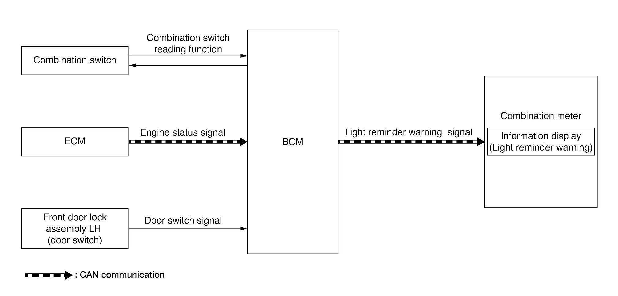
DESIGN/PURPOSE
When the driver is exiting the vehicle while the engine status is other than running and the headlamps are ON, the light reminder warning (information display) displays a warning in the information display to alert the driver.
| Symbol | Message |
|---|---|
|
|
Reminder Turn OFF Headlights |

| Symbol | Message |
|---|---|
|
|
Reminder Turn OFF Headlights |
SIGNAL PATH
-
BCM reads the status of the combination switch.
-
BCM detects the vehicle condition depending on the engine status signal received from the ECM via CAN communication.
-
BCM judges the light reminder warning (information display) by the lighting switch signal, front door switch LH signal and engine status signal. BCM transmits the light reminder warning signal to the combination meter via CAN communication.
-
When the combination meter receives the light reminder warning signal, the light reminder warning pop-up screen appears in the information display.
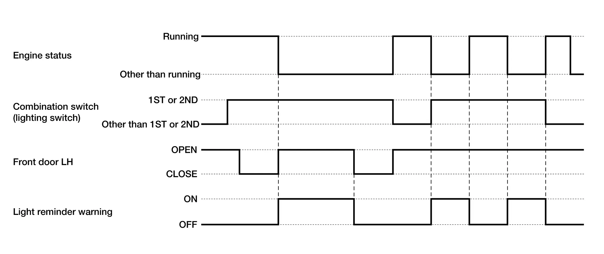
WARNING/INDICATOR OPERATING CONDITION
When all of the following conditions are satisfied:
-
Engine status is other than running
-
Lighting switch 1ST or 2ND
-
Front door LH OPEN [front door lock assembly LH (door switch) ON]
WARNING/INDICATOR CANCEL CONDITION
When any of the following conditions are satisfied:
-
Engine status is running
-
Lighting switch other than 1ST or 2ND
-
Front door LH CLOSED [front door lock assembly LH (door switch) OFF]
TIMING CHART
Headlamp Warning System
System Description
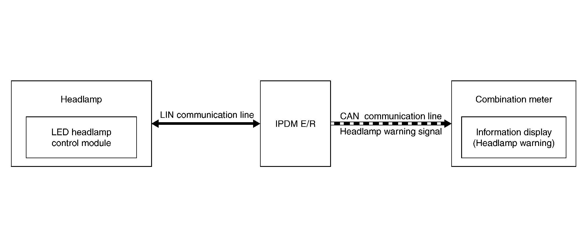
SYSTEM DIAGRAM
SIGNAL TRANSMISSION FUNCTION LIST
| Signal name | Input | Output | Description |
|---|---|---|---|
| Headlamp warning signal | LED headlamp control module | BCM (CAN) | Inputs the headlamp warning signal and transmits it via CAN communication. |
DESIGN/PURPOSE
Headlamp warning warns the driver that there is a malfunction in LED headlamp system.
| Symbol | Message |
|---|---|
| — |
Headlight System Error See Owner′s Manual |
SIGNAL PATH
-
When the LED headlamp control module detects a malfunction of headlamp (LO) circuit the headlamp warning signal is transmitted to the IPDM E/R via LIN communication.
-
When the IPDM E/R receives the headlamp warning signal (via LIN communication) or the IPDM E/R detects a malfunction of LIN communication, the IPDM E/R transmits the headlamp warning signal to the combination meter via CAN communication.
-
When the ignition switch is ON and the combination meter receives the headlamp warning signal via CAN communication, the combination meter displays the headlamp warning on the information display.
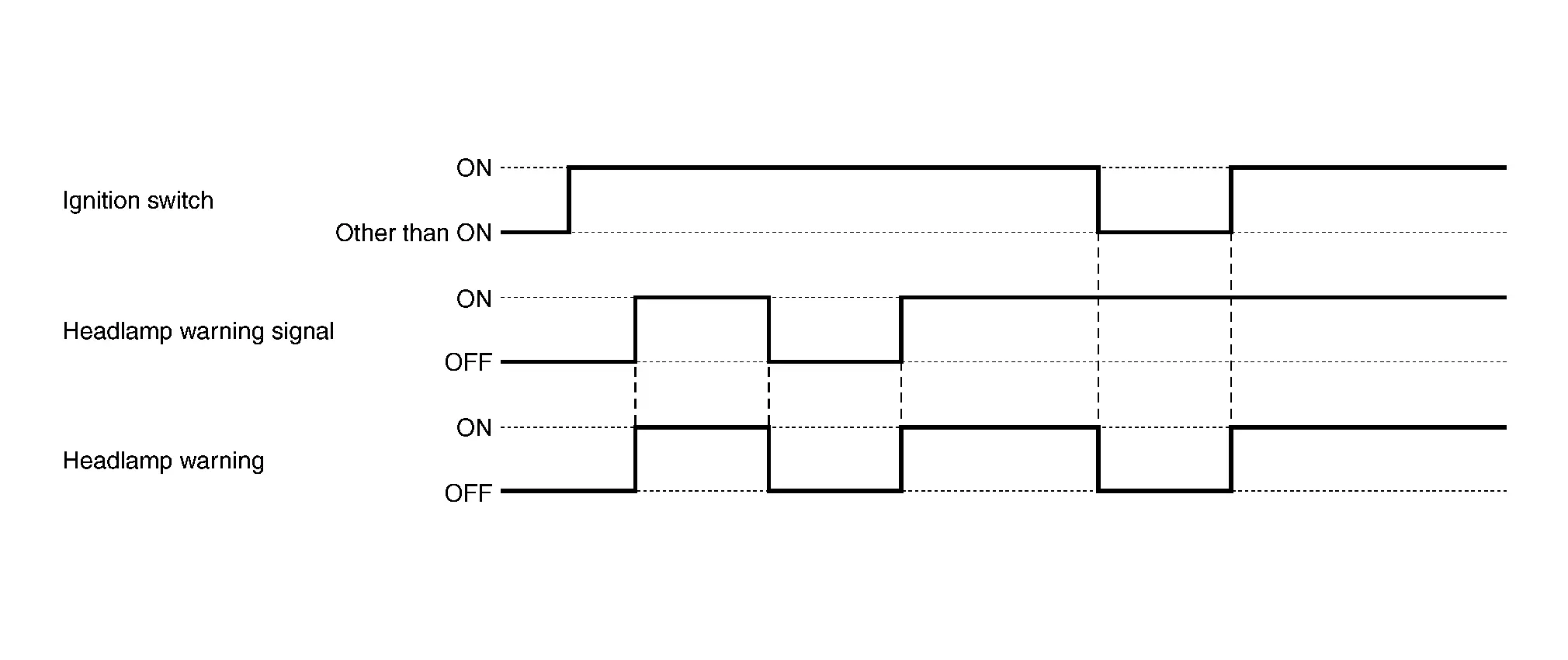
WARNING/INDICATOR OPERATING CONDITION
When all of the following conditions are satisfied:
-
Ignition switch ON
-
Headlamp warning signal (via CAN communication) is ON
WARNING/INDICATOR CANCEL CONDITION
When any of the following conditions are satisfied:
-
Ignition switch other than ON
-
Headlamp warning signal (via CAN communication) is OFF
TIMING CHART
Other materials:
Removal and Installation. Intelligent Key Unit
Removal and Installation
REMOVALCAUTION:
When replacing the Intelligent Key unit, always replace it
with a new one. The functions controlled by the Intelligent Key unit
does not operate properly in case of reuse of the Intelligent Key unit
from another Nissan Ariya vehicle.
Remove the instr ...
Poste de conduite
Cette vue d’ensemble du poste de conduite du Nissan Rogue vous aide à repérer rapidement les commandes essentielles, que vous conduisiez en ville ou sur autoroute. Selon la finition de votre Nissan Rogue, certaines fonctions peuvent être présentes (signalées par *), notamment ProPILOT Assist ...
Basic Inspection. Diagnosis and Repair Work Flow
Work Flow (Heated Steering Wheel)
DETAILED FLOWOBTAIN INFORMATION ABOUT SYMPTOM
Interview the customer to obtain the malfunction information
(conditions and environment when the malfunction occurred) as much as
possible when the customer brings the Nissan Ariya vehicle in.
>>
GO TO ...