Nissan Rogue (T33) 2021-Present Service Manual: Component Parts
Exterior Lamp Appearance
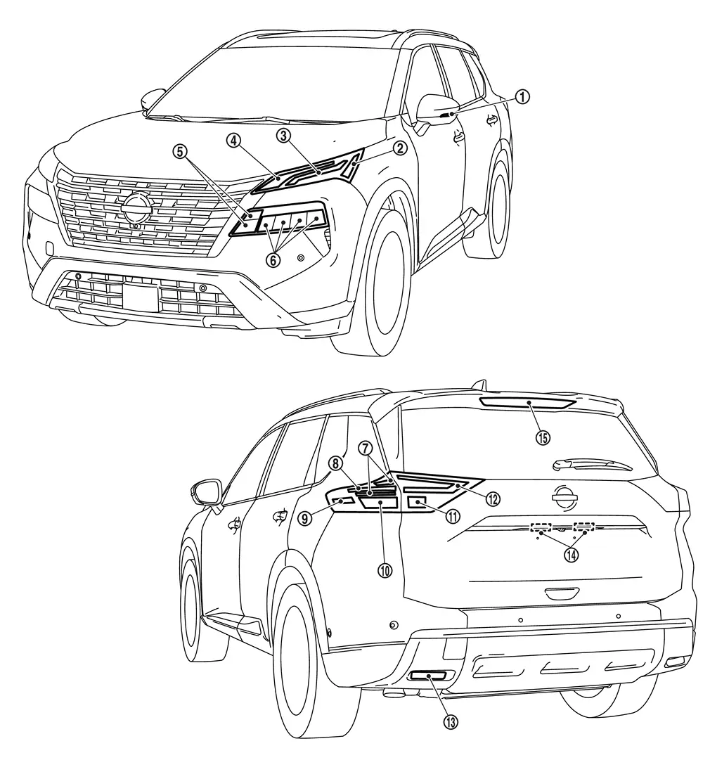
| 1. | Side turn signal lamp (if equipped) | 2. | Front side marker lamp | 3. | Front turn signal lamp (bulb type) |
| 4. | Parking lamp/Daytime running light/Front turn signal lamp (LED type) | 5. | Headlamp (Hi) | 6. | Headlamp (Lo) |
| 7. | Stop lamp | 8. | Tail lamp/Stop lamp | 9. | Rear side marker lamp |
| 10. | Rear turn signal lamp | 11. | Back-up lamp | 12. | Tail lamp |
| 13. | Rear reflex reflector | 14. | License plate lamp | 15. | High-mounted stop lamp |
Bulb Specifications
| Item | Type | Wattage (W) | |
|---|---|---|---|
| Headlamp | Headlamp (Hi) | LED | — |
| Headlamp (Lo) | LED | — | |
| Front combination lamp [front turn signal lamp (bulb type)] | Front turn signal lamp | 7444NA | 28/8W |
| Parking lamp/Daytime running light | LED | — | |
| Front side marker lamp | W5W | 5W | |
| Front combination lamp [front turn signal lamp (LED type)] | Parking lamp/Daytime running light/Front turn signal lamp | LED | — |
| Front side marker lamp | W5W | 5W | |
| Side turn signal lamp | Door mirror type | LED | — |
| Rear combination lamp (body side) | Stop lamp | LED | — |
| Tail lamp | LED | — | |
| Rear turn signal lamp | WY21W (amber) | 21W | |
| Rear side marker lamp | W5W | 5W | |
| Rear combination lamp (back door side) | Tail lamp | LED | — |
| Back-up lamp | W16W | 16W | |
| License plate lamp* | W5W | 5W | |
| High-mounted stop lamp | LED | — | |
*: Replacement of a single part is not possible because license plate lamp cannot disassemble. For replacement, replace license plate lamp as a set.
Component Parts Location (With Type A Meter)
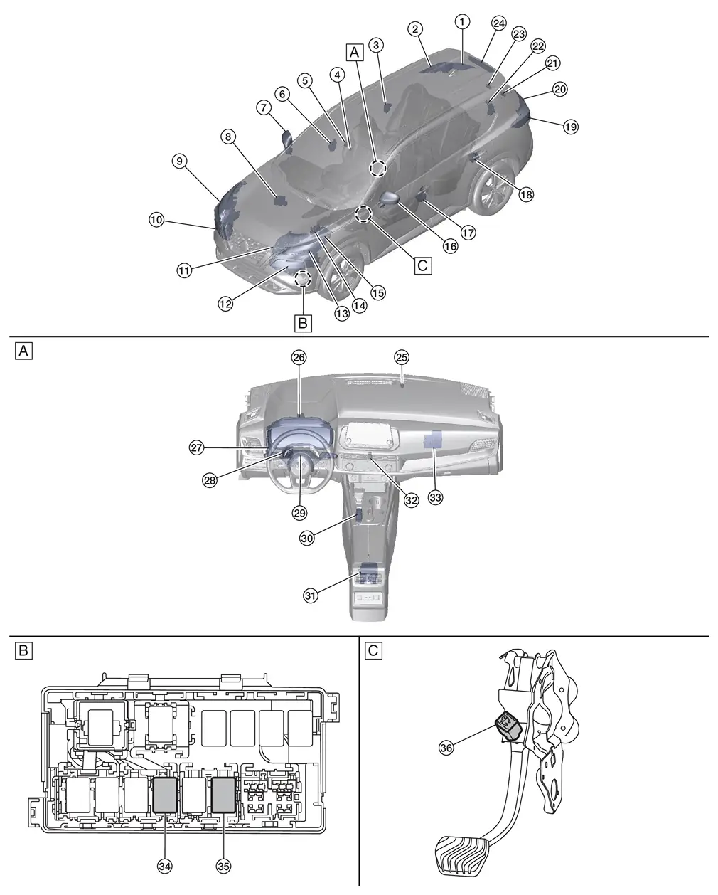
| A. | Instrument panel assembly | B. | Relay box (view with relay box removed) | C. | Brake pedal assembly (view with brake pedal assembly removed) |
| No. | Component | Function | |
|---|---|---|---|
| 1. | Rear combination lamp RH (back door side) | Tail lamp | Refer to Bulb Specifications. |
| Back-up lamp | |||
| 2. | Rear combination lamp RH (body side) | Tail lamp | Refer to Bulb Specifications. |
| Rear side marker lamp | |||
| Rear turn signal lamp | |||
| Stop lamp | |||
| 3. | Rear door lock assembly RH (door switch) |
Transmits the door switch signal to the BCM. Refer to Door Lock Assembly for detailed component location. |
|
| 4. | Rain and light sensor (if so equipped) |
Transmits the light sensor signal to the BCM via LIN communication. Refer to Rain and Light Sensor for detailed component location. |
|
| 5. | Front camera unit |
Front camera unit detects a Nissan Ariya vehicle ahead or when an oncoming vehicle appears to operate the high beam assist (HBA) system. Refer to Front Camera Unit for detailed component location. |
|
| 6. | Front door lock assembly RH (door switch) |
Transmits the door switch signal to the BCM. Refer to Door Lock Assembly for detailed component location. |
|
| 7. | Door mirror RH | Side turn signal lamp | Refer to Bulb Specifications. |
| 8. | ABS (Anti-locking Braking System) actuator and electric unit (control unit) |
Transmits the Nissan Ariya vehicle speed signal and parking brake status signal via CAN communication. Refer to ABS Actuator and Electric Unit (Control Unit) for detailed component location. |
|
| 9. | Front combination lamp RH | Headlamp (HI) | Refer to Bulb Specifications. |
| Headlamp (LO) | |||
| Parking lamp | |||
| Daytime running light | |||
| Front turn signal lamp | |||
| Front side marker lamp | |||
| 10. | Front combination lamp RH | Parking lamp | Refer to Bulb Specifications. |
| Daytime running light | |||
| LED headlamp control module | Refer to LED Headlamp Control Module. | ||
| 11. | CVT unit | TCM |
Transmits the shift position signal via CAN communication. Refer to TCM for detailed component location. |
| 12. | Front combination lamp LH | Parking lamp | Refer to Bulb Specifications. |
| Daytime running light | |||
| LED headlamp control module | Refer to LED Headlamp Control Module. | ||
| 13. | Front combination lamp LH | Headlamp (HI) | Refer to Bulb Specifications. |
| Headlamp (LO) | |||
| Parking lamp | |||
| Daytime running light | |||
| Front turn signal lamp | |||
| Front side marker lamp | |||
| 14. | ECM (Engine Control Module) |
Transmits the engine status signal via CAN communication. Refer to ECM for detailed component location. |
|
| 15. | IPDM E/R (Intelligent Power Distribution Module Engine Room) |
IPDM E/R Smart FET (field-effect transistor) supplies voltage to the loads according to the request from the BCM via CAN communication. Refer to System Description. |
|
| 16. | Door mirror LH | Side turn signal lamp | Refer to Bulb Specifications. |
| 17. | Front door lock assembly LH (door switch) |
Transmits the door switch signal to the BCM. Refer to Door Lock Assembly for detailed component location. |
|
| 18. | Rear door lock assembly LH (door switch) |
Transmits the door switch signal to the BCM. Refer to Door Lock Assembly for detailed component location. |
|
| 19. | Rear combination lamp LH (body side) | Tail lamp | Refer to Bulb Specifications. |
| Rear side marker lamp | |||
| Rear turn signal lamp | |||
| Stop lamp | |||
| 20. | Rear combination lamp RH (back door side) | Tail lamp | Refer to Bulb Specifications. |
| Back-up lamp | |||
| 21. | License plate lamp LH | Refer to Bulb Specifications. | |
| 22. | Back door lock assembly (ajar switch) |
Transmits the ajar switch signal to the BCM. Refer to Back Door Lock Assembly for detailed component location. |
|
| 23. | License plate lamp RH | Refer to Bulb Specifications. | |
| 24. | High-mounted stop lamp | Refer to Bulb Specifications. | |
| 25. | Optical sensor (if so equipped) | Refer to Optical Sensor. | |
| 26. | Combination meter |
|
|
| 27. | BCM (Body Control Module) |
|
|
| 28. | Chassis control module |
Turns the stop lamp relay ON/OFF for the AEB function. Refer to Chassis Control Module for detailed component location. |
|
| 29. | Combination switch |
Transmits the status of the combination switch to the BCM. Refer to System Description. |
|
| 30. | Parking brake switch |
Transmits the parking brake switch signal to the ABS actuator and electric unit (control unit). Refer to Parking Brake Switch for detailed component location. |
|
| 31. | Air bag diagnosis sensor unit |
Transmits the car crash information signal to the BCM via CAN communication for the auto hazard function. Refer to Component Parts Location for detailed component location. |
|
| 32. | Hazard switch | Refer to Hazard Switch. | |
| 33. | Intelligent Key unit |
Transmits the door lock/unlock request signal via CAN communication. Refer to Intelligent Key Unit for detailed component location. |
|
| 34. | Back-up lamp relay |
|
|
| 35. | Stop lamp relay |
|
|
| 36. | Stop lamp switch | Refer to Stop Lamp Switch. | |
Component Parts Location (With Type B Meter)
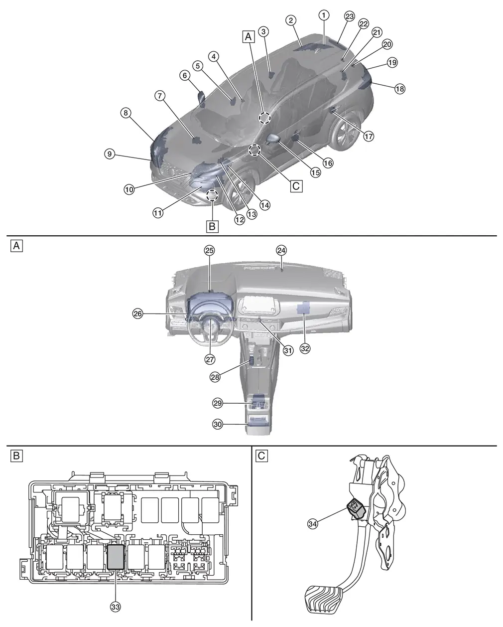
| A. | Instrument panel assembly | B. | Relay box (view with relay box removed) | C. | Brake pedal assembly (view with brake pedal assembly removed) |
| No. | Component | Function | |
|---|---|---|---|
| 1. | Rear combination lamp RH (back door side) | Tail lamp | Refer to Bulb Specifications. |
| Back-up lamp | |||
| 2. | Rear combination lamp RH (body side) | Tail lamp | Refer to Bulb Specifications. |
| Rear side marker lamp | |||
| Rear turn signal lamp | |||
| Stop lamp | |||
| 3. | Rear door lock assembly RH (door switch) |
Transmits the door switch signal to the BCM. Refer to Door Lock Assembly for detailed component location. |
|
| 4. | Front camera unit |
Front camera unit detects a Nissan Ariya vehicle ahead or when an oncoming vehicle appears to operate the high beam assist (HBA) system. Refer to Front Camera Unit for detailed component location. |
|
| 5. | Front door lock assembly RH (door switch) |
Transmits the door switch signal to the BCM. Refer to Door Lock Assembly for detailed component location. |
|
| 6. | Door mirror RH | Side turn signal lamp (if so equipped) | Refer to Bulb Specifications. |
| 7. | ABS (Anti-locking Braking System) actuator and electric unit (control unit) |
Transmits the Nissan Ariya vehicle speed signal and parking brake status signal via CAN communication. Refer to ABS Actuator and Electric Unit (Control Unit) for detailed component location. |
|
| 8. | Front combination lamp RH | Headlamp (HI) | Refer to Bulb Specifications. |
| Headlamp (LO) | |||
| Parking lamp | |||
| Daytime running light | |||
| Front turn signal lamp | |||
| Front side marker lamp | |||
| 9. | Front combination lamp RH | Parking lamp | Refer to Bulb Specifications. |
| Daytime running light | |||
| LED headlamp control module | Refer to LED Headlamp Control Module. | ||
| 10. | CVT unit | TCM |
Transmits the shift position signal via CAN communication. Refer to TCM for detailed component location. |
| 11. | Front combination lamp LH | Parking lamp | Refer to Bulb Specifications. |
| Daytime running light | |||
| LED headlamp control module | Refer to LED Headlamp Control Module. | ||
| 12. | Front combination lamp LH | Headlamp (HI) | Refer to Bulb Specifications. |
| Headlamp (LO) | |||
| Parking lamp | |||
| Daytime running light | |||
| Front turn signal lamp | |||
| Front side marker lamp | |||
| 13. | ECM (Engine Control Module) |
Transmits the engine status signal via CAN communication. Refer to ECM for detailed component location. |
|
| 14. | IPDM E/R (Intelligent Power Distribution Module Engine Room) |
IPDM E/R Smart FET (field-effect transistor) supplies voltage to the loads according to the request from the BCM via CAN communication. Refer to System Description. |
|
| 15. | Door mirror LH | Side turn signal lamp (if so equipped) | Refer to Bulb Specifications. |
| 16. | Front door lock assembly LH (door switch) |
Transmits the door switch signal to the BCM. Refer to Door Lock Assembly for detailed component location. |
|
| 17. | Rear door lock assembly LH (door switch) |
Transmits the door switch signal to the BCM. Refer to Door Lock Assembly for detailed component location. |
|
| 18. | Rear combination lamp LH (body side) | Tail lamp | Refer to Bulb Specifications. |
| Rear side marker lamp | |||
| Rear turn signal lamp | |||
| Stop lamp | |||
| 19. | Rear combination lamp RH (back door side) | Tail lamp | Refer to Bulb Specifications. |
| Back-up lamp | |||
| 20. | License plate lamp LH | Refer to Bulb Specifications. | |
| 21. | Back door lock assembly (ajar switch) |
Transmits the ajar switch signal to the BCM. Refer to Back Door Lock Assembly for detailed component location. |
|
| 22. | License plate lamp RH | Refer to Bulb Specifications. | |
| 23. | High-mounted stop lamp | Refer to Bulb Specifications. | |
| 24. | Optical sensor | Refer to Optical Sensor. | |
| 25. | Combination meter |
|
|
| 26. | BCM (Body Control Module) |
|
|
| 27. | Combination switch |
Transmits the status of the combination switch to the BCM. Refer to System Description. |
|
| 28. | Parking brake switch |
Transmits the parking brake switch signal to the ABS actuator and electric unit (control unit). Refer to Parking Brake Switch for detailed component location. |
|
| 29. | Air bag diagnosis sensor unit |
Transmits the car crash information signal to the BCM via CAN communication for the auto hazard function. Refer to Component Parts Location for detailed component location. |
|
| 30. | ADAS (Advanced Driver Assistance System) control unit 2 |
Transmits the stop lamp request signal via CAN communication for the AEB function. Refer to ADAS Control Unit 2 for detailed component location. |
|
| 31. | Hazard switch | Refer to Hazard Switch. | |
| 32. | Intelligent Key unit |
Transmits the door lock/unlock request signal via CAN communication. Refer to Intelligent Key Unit for detailed component location. |
|
| 33. | Back-up lamp relay |
|
|
| 34. | Stop lamp switch | Refer to Stop Lamp Switch. | |
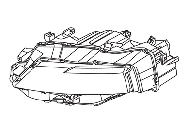
LED Headlamp Control Module
-
LED headlamp control module is integrated with the front combination lamp.
-
When power is supplied from the battery and the LED headlamp control module receives the control signal from the IPDM E/R, the LED headlamp control module internally calculates the supplied power. The calculated power is distributed to multiple LEDs that consist of circuit boards and other components, illuminating each lamp.
-
When a malfunction is detected in the headlamp (low) circuit, the LED headlamp control module outputs a headlamp warning signal to the IPDM E/R via LIN communication to inform the driver of the malfunction.
Optical Sensor
-
The optical sensor is installed in the top center of the instrument panel assembly.
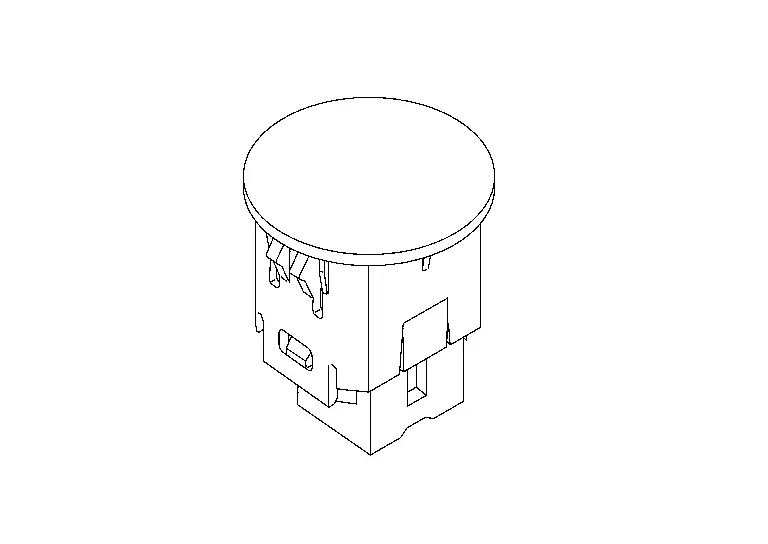
-
The optical sensor converts outside brightness (lux) to voltage and transmits the optical sensor signal to the BCM.
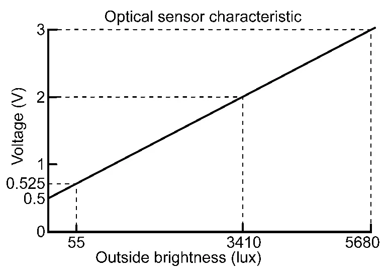
-
The optical sensor outputs voltage signals to the BCM according to the brightness of ambient light. This sensor increases the voltage output according to increases in brightness of ambient light.
Rain and Light Sensor
-
The rain and light sensor is installed on the windshield.
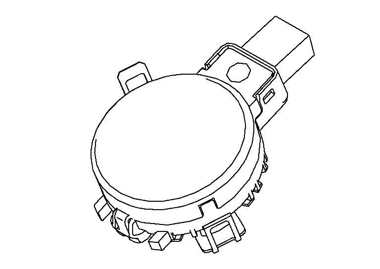
-
Detects outside brightness and transmits the light sensor signal to the BCM via LIN communication.
Hazard Switch
-
The hazard switch is installed in the center of the instrument panel assembly.
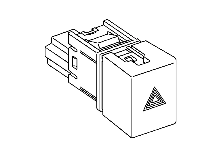
-
Outputs the ON/OFF status of the hazard switch to the BCM, flashing the hazard warning lamps.
Stop Lamp Switch
-
The stop lamp switch is installed on the brake pedal assembly.
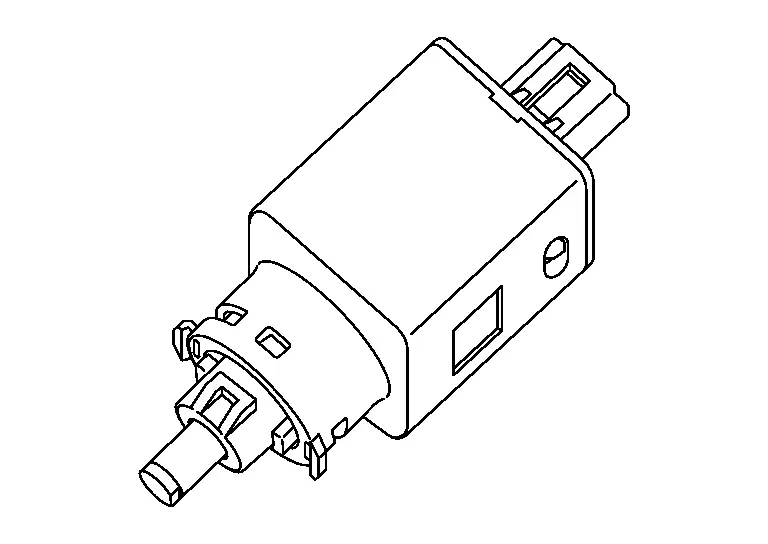
-
The BCM detects the ON/OFF status of the stop lamp switch and illuminates the stop lamp.
Other materials:
P0122 Tp Sensor
DTC Description
DTC DETECTION LOGIC DTC
CONSULT screen terms
(Trouble diagnosis content)
DTC detection condition
P0122
00
TP SEN 2/CIRC-B1
(Throttle/Pedal position sensor/switch “A” circuit low)
Diagnosis condition
Engine running at idle
Signal (terminal)
TP s ...
Component Parts /circuit Diagnosis. Heated Steering Wheel System
Component Function Check
CHECK HEATED STEERING WHEEL SYSTEM
Check the heated steering wheel system. Refer to System Description (Heated Steering Wheel).
Is the inspection result normal?
YES>>
Inspection End.
NO>>
Go toDiagnosis Procedure.
Diagnosis Procedure
CHECK POWER SOURCE ...
C1f00-54 Hands Off Threshold Incomplete
Without Propilot Assist 2.1
DTC Description
DTC DETECTION LOGIC DTC
CONSULT screen terms
(Trouble diagnosis content) DTC detection condition
C1F00
54
CONTROL UNIT
(Control unit)
Diagnosis condition
—
Signal (terminal)
—
Threshold
Steering Torque C ...